Motorola index
Back to Home
MaxTrac 800 / 900 MHz Radios
By Robert W. Meister WA1MIK

|
MaxTrac index Motorola index Back to Home |
Replacing Front End Filters in MaxTrac 800 / 900 MHz Radios By Robert W. Meister WA1MIK |
|
Stock Radios:
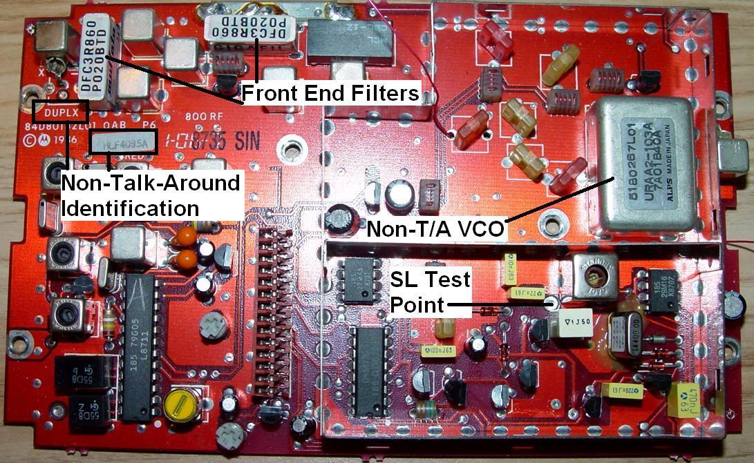
The 800 MHz MaxTrac radios are designed to receive 851-870 MHz. They achieve this selectivity through the use of two ceramic dielectric filters in the front end, made by muRata Corporation. These are part number DFC3R860P020BTD. This tells us they have three sections, are tuned to a center frequency of 860 MHz, and have a total bandwidth of 20 MHz (from 850 to 870 MHz). These have very high loss in the 902-928 MHz amateur band as they are specifically designed to reject signals outside the 850-870 MHz range. Here's a photo of an 800 MHz RF board showing these front-end filters:
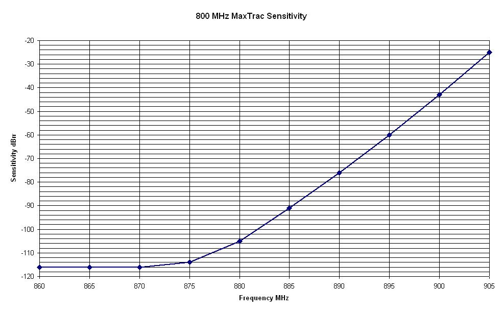
Here's a sensitivity graph of a stock 800 MHz radio. The part below 860 MHz is a mirror image of the part seen here (click on it for a bigger image):
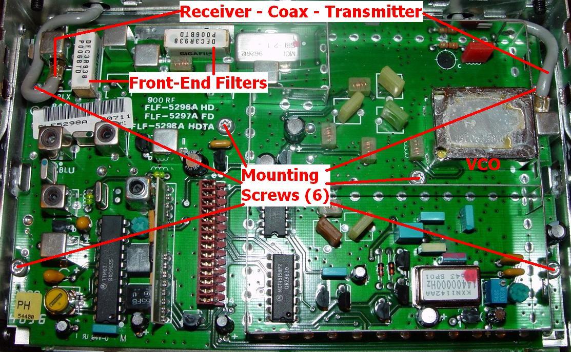
The 900 MHz MaxTrac radios are designed to to receive 935-941 MHz. They achieve this selectivity the same as the 800 MHz radios, by using a pair of muRata filters, part number DFC3R938P006BTD. This tells us they have three sections, are tuned to a center frequency of 938 MHz, and have a total bandwidth of 6 MHz (from 935 to 941 MHz). These will allow the radio to receive some signals at 928 MHz but have very high loss at 902 MHz as they too are specifically designed to reject signals outside the 935-941 MHz range. Here's a photo of a 900 MHz RF board showing these front-end filters:
Here's a sensitivity graph of a stock 900 MHz radio (click on it for a bigger image):

On either radio, shorting the front-end filters will improve the sensitivity in the 900 MHz amateur band, but with no filtering, this drastically increases their susceptibility to unwanted signals. Alternatively, you can replace the stock filters with 915 MHz units that will allow the receiver to meet or exceed factory sensitivity specifications for signals in the amateur band. This article will deal with the process of replacing these filters.
I've found that the Toko 6DFB-915E-10 filters are exact replacements for the muRata filters. They have three sections, a center frequency of 915 MHz, and a total bandwidth of 26 MHz. They have the same mounting arrangement and footprint and can be obtained for between $10 and $15 each. You'll need two filters for each radio. A 100kb Toko datasheet can be found here.
Removing the Original Filters:
The first step is to make sure the receiver is working properly on the original band and that the sensitivity is better than 0.4uV for 20dB quieting. If you have to do other work on the radio, such as modify the VCO or replace the firmware, do that first and make sure the receiver is still operating, even though it may be much less sensitive.
Unplug the radio. Remove the two T15 screws holding the control head to the radio. Remove the four T10 flat-head screws (two on each side) holding the plastic covers on the radio. Pull the control head off the radio slightly and remove the covers.
Remove the shield over the entire RF board, then remove the shield over the VCO area. A small screwdriver can be used to pry up the corners of the shields. Unplug the two gray RF cables from the RF board, then remove the six T10 screws holding the RF board to the chassis. Their locations are shown in the photo above. Gently remove the RF board by pulling it straight up. The only things keeping it in place are the pins coming from the logic board connector.
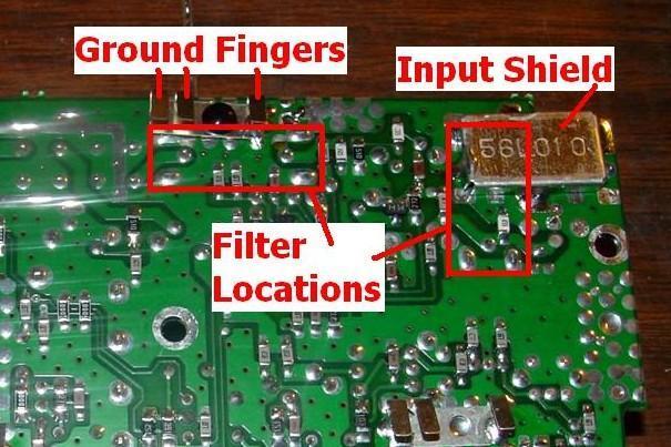
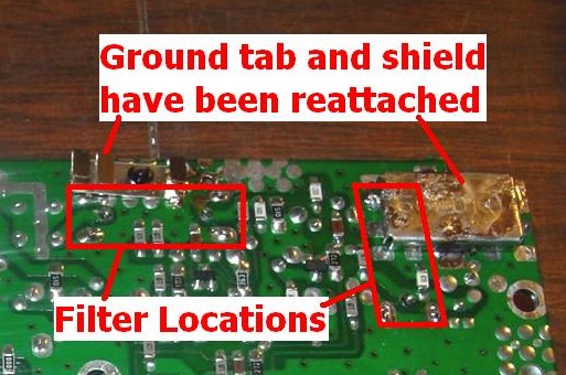
Part of one filter is covered by a shield underneath the board. This must be removed to access that area of the board in order to remove the filter. Flip the board over; all work is done on the solder side of the board. You will see this shield, pointed out below:
I use a 100/140-watt Weller soldering gun to heat up each side of the shield. Then I use a plunger-style desoldering tool to suck the solder away from the junction of the shield and the circuit board. There are usually three or four points where it's soldered around the outer edge. Once most of the solder is gone, take a small knife and start prying one corner up while the gun is still heating the shield. It should fall right off. Be careful, it will be VERY hot. Clean off any remaining solder from the pads on the board by using a small soldering iron to heat them. There are two tabs on the shield that fit into holes or slots on the circuit board; make sure these are clear of solder.
On the board I converted, there was also a set of ground contacts that were covering one mounting tab of the other filter. This was soldered to the board but it was also held in position with a black plastic rivet. I removed the rivet and unsoldered the contact material. If your board has a much larger ground contact without the black plastic rivet, it should not cause interference and you can just leave it in place.
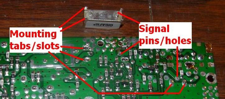
Once the shield and ground contacts have been removed, you will have full access to the two signal pins and four mounting tabs for each filter.
Using the same 100/140-watt soldering gun, rest the tip on its side at the junction of the circuit board and the mounting tab, and push it against one of the mounting tabs. As the solder melts, gently push the mounting tab so it's in the center of the slot. Keep the heat on for another five seconds (to make sure the solder on the other side of the board is also molten), the suck the solder out of the slot. The mounting tab should be completely free of all solder and should be in the middle of the slot. Use a small screwdriver or a knife blade to move the tab; it should be easily moved and not stuck to the slot. If you don't get all the solder out the first time, reheat the tab, add a bit of fresh solder, let it all melt, and suck it out again. You must get the entire tab hot enough to melt the solder on both sides of the circuit board so it all can be removed at once. Don't worry; the filter and circuit board can take the heat. Do all four mounting tabs on each filter.
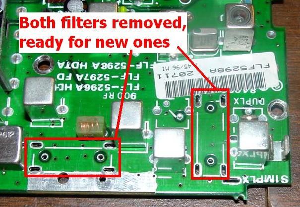
The filter is now held to the board only by its two signal pins. I use a 35w soldering iron to heat each pin and suck the solder away. It's usually not possible to get it all out of the hole, so I don't even try. After removing what comes out easily, I use the iron to heat and push each signal pin a little at a time, while gently rocking the filter or pulling it off the board (remember - the filters may still be quite hot for several minutes after freeing up their mounting tabs). This sometimes takes more than two hands and it always takes several attempts, but eventually you'll get the filter to just drop off the board. If necessary, remove any remaining solder from the mounting slots and signal pin holes once the filter has been removed. It'll be a lot easier now that there's room for some air to get through them. The photo below shows the board with one filter removed:
Here's what the top of the board looks like after removing one filter using the method described above. Note that there's not a trace of solder around the mounting tab slots. Compare this to the tabs of the other filter that's still soldered in:
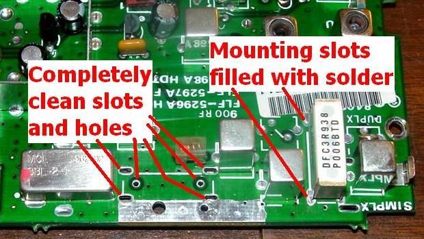
Repeat this process for the other filter. Here's what the top of the board looks like with both filters removed. There has been no work performed on this side of the board. The slots and holes are completely clear.
The hard part is done. Now using an old toothbrush and some isopropyl alcohol, clean the flux off the board and inspect the foils. They should not be deformed or lifting off the circuit board. If they are, try to repair any damage at this point. Make sure all the slots and holes are completely clear.
You can remove the filters using other more destructive methods. The process detailed above gets the filter out with no damage to the board or the filter, and it could be used elsewhere if necessary or even put back into the radio. This method works well for me but your experience may vary.
An alternative method (which I have not personally used) still requires the shield and ground clip to be removed, but instead of unsoldering the filter from the circuit board, you peel the label off the top and heat the solder joint on the side of the filter body. With a knife blade, spread the mounting clip just enough to remove any solder attaching the body to the clip. Then the filter body can be pulled upward and removed from the clip, leaving the two signal pins and the mounting clip soldered to the board. You can then remove the signal pins by heating them up with a soldering iron and pulling the pins out of the board, followed by removing the solder from the empty holes. The mounting clip will be easier to unsolder now that the big heat sink (the filter body) has been removed.
I experienced the result of replacing the filter body (and possibly the signal pins as well) using this method. I had acquired several 800 MHz RF boards where a previous owner had removed the filter bodies, took the mounting clips off the new filters, and put the new filter bodies into the original mounting clips, which remained soldered to the circuit board. The filter body must be firmly soldered to the mounting clip, as the ground connection is an important part of the filter's circuitry. On the boards I received, none of the filter bodies were soldered back to the mounting clips. The result was that none of these RF boards had decent sensitivity; they were all in the 2-5 microvolt range for 20dB quieting. I had to remove all of the filters, their signal pins and mounting clips, then install brand new Toko filters to get the boards functioning to rated specs. I don't know if it was the method that was at fault, if the original signal pins were left installed, the lack of soldering the filter body to the mounting clip, or if the filters were defective.
Another method that seems to be popular with Kenwood owners, is to break the ceramic filter body from the top of the radio, remove it in pieces, then unsolder the two signal pins and finally the mounting clip. See this page for a description of that method. I prefer not to destroy things in the process of removing them, if possible.
Installing the New Filters:
Luckily, putting the new filters into the nice clean board is a piece of cake. The only difficulty is that the holes are now so clean that the filters will not stay in the board when you flip the board over to solder them in.
The filters can be installed in either direction, but I usually orient them so I can read the part number without removing the board. The filters are identical and can go into either spot on the circuit board. Do one filter at a time. Insert it from the top of the board, hold it in place, and flip the board over. Use the handle of a small screwdriver or other hand tool to support the filter so it rests flush against the circuit board when positioned for soldering. I then use the soldering iron and solder just one signal pin. Now I apply pressure to the filter to push it against the circuit board while I re-heat that signal pin. Make sure the filter is flat and flush against the top of the circuit board and also perfectly vertical. Then solder the remaining signal pin. This will hold the filter in place. Now use the soldering gun to heat each mounting tab and the nearby foil, and add sufficient solder to fill the slot and form a nice fillet around the tab. Let the tab get hot enough so the solder flows to the other side of the circuit board and forms a nice joint on both sides. Don't heat the joint from the top of the board; apply enough heat and solder to do the job from the underneath and let capillary action draw the solder into the slot and onto the top of the board. Repeat this process with the other filter. Let the board cool down for a few minutes and clean the remaining flux off the board in the area of the filters and the corner where the shield and ground tabs were mounted. I use an old toothbrush and some isopropyl alcohol as a flux remover. Check for obvious solder shorts and bad joints. The photo below shows the job at this stage of completion:
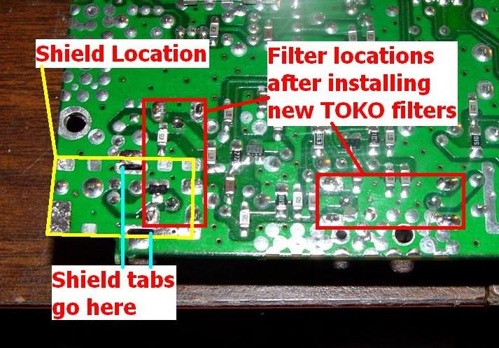
Position the shield so its two tabs are in the slots that you cleaned out a while ago. It should sit completely flush on the circuit board. It can be installed in either of two ways, so make sure it doesn't stick out over the edge of the RF board. Solder it in place using the 100/140-watt gun. Apply the tip to the joint at one tab and the circuit board and add solder. Do both tabs and a spot at the two short ends of the shield. If you had to remove the ground tab at the edge of the board, reinstall it now. Hold it in position so the hole lines up but do NOT install the plastic rivet until you've finished soldering it, as the heat will melt the plastic. After everything cools, install the rivet and use the toothbrush and alcohol to clean the flux from the area of the shield. When you're finished, the board should look just like it did before you started except for the different filters:
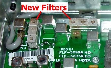
Here's what the top of the board looks like with the new filters:
Reinstall the RF board into the radio chassis by lining it up with the pins coming from the logic board. Push the RF board fully onto the chassis, reinstall the six T10 screws, plug the two coax cables back in, install the VCO and main shields, put the covers and control head back on using their screws, and you're done. There's no adjustment or alignment necessary (or possible) with these filters.
This entire modification process took me 45 minutes from start to finish, including taking breaks for the photographs. I've done them in less time, and after replacing the filters in nearly a dozen radios, I've refined the procedure considerably.
Results:
The three filters used in these radios have the following specifications. Graphs of the two muRata filters are shown above. A graph of the Toko filter is shown below. All frequencies are in MHz unless otherwise noted. The last two columns show the 20dB quieting sensitivity. A signal level of -116dBm is exactly 0.354 microvolts, very decent for 20dB quieting.
| ||||||||||||||||||||||||||||||
The muRata equivalent to the Toko filter is DFC3R915P025BTD. This has a center frequency of 915 MHz and a bandwidth of 25 MHz, so it's just a bit narrower than the Toko filter. Install whichever ones you can buy.
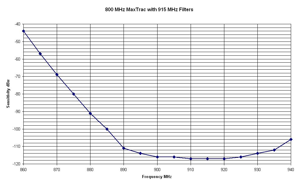
Here's a sensitivity graph of an 800 MHz radio with the new Toko filters (click on it for a bigger image). The response is a mirror image around the center frequency of 915 MHz. The results in a 900 MHz radio are exactly the same, although the VCO in my radio won't operate below about 920 MHz.
Tools Used:
Acknowledgements and Credits:
I have sold all of the filters I had bought. I have no more. Don't even ask me; use Google.
MaxTrac is a trademark of Motorola, Inc.
Other part numbers, terms, and brands are trademarks of their respective companies.
Contact Information:
The author can be contacted at: his-callsign [ at ] comcast [ dot ] net.
Back to the top of the page
Up one level (MaxTrac index)
Up two levels (Motorola index)
Back to Home
This page originally posted on Sunday 11-Feb-2007
Article text, artistic layout, and hand-coded HTML © Copyright 2007 by Robert W. Meister WA1MIK.
This web page, this web site, the information presented in and on its pages and in these modifications and conversions is © Copyrighted 1995 and (date of last update) by Kevin Custer W3KKC and multiple originating authors. All Rights Reserved, including that of paper and web publication elsewhere.