Motorola index
Back to Home
Transmit PL Mute Circuit
By Robert W. Meister WA1MIK

|
MaxTrac index Motorola index Back to Home |
MaxTrac and GM300 Transmit PL Mute Circuit By Robert W. Meister WA1MIK |
|
Background:
This write-up describes the analysis and circuit modifications to add an external transmit PL mute circuit to a Motorola MaxTrac (or similar) mobile radio. My tests were done on a radio with an HLN9313 16-pin logic board that has many of the resistors on the top; other boards may have them on either side. You may have to get innovative to connect a wire to the proper spot.
I hear some of you asking: "Isn't that available at the accessory jack?" Yes, you can program "TX PL Inhibit" onto one of several pins of the 16-pin accessory jack, however not all radios have the 16-pin logic board. Also, some radios and firmware revisions will cause the transmitter to stop transmitting (the RF actually drops) for a short time when this line is activated, and that just is not acceptable to me.
The scope trace below shows the TX PL Inhibit input signal at the top (in red) going to ground (the trigger), and the 9.6VDC power feeding the RF power amplifier at the bottom (in blue). You can see that the voltage goes away 17 milliseconds later, even though it's only for one millisecond, interrupting the RF signal. The PL signal has gone away long ago. This drop in RF is enough to be seen on a Bird wattmeter.
The radio abruptly stops the PL signal within 10 milliseconds; it does not send out the "reverse-burst" as part of the PL turn-off sequence. The PL signal is restored 22 milliseconds after the line is released. This is fine as long as nothing else is affected. I have a feeling that Motorola intended that the "TX PL Inhibit" input be activated BEFORE the radio actually started transmitting, so PL wouldn't be present for the entire transmission, rather than to be activated WHILE it was transmitting. Information from a reader confirms that you should only alter this signal while the radio is not transmitting.
The components shown below can easily be soldered together, wrapped in tape, and stuffed inside the radio. I ran a wire up to an unused pin on the MIC jack to control the activation of this circuit.
The "TX PL Inhibit" input works with a radio programmed to transmit DPL, however the DPL data stream is abruptly stopped and the turn-off code, like the PL reverse-burst, is not sent out when you activate this signal. I have tried this circuit with a GM300 radio programmed for DPL; it works but the receiver takes almost a second to squelch up after the DPL signal is disabled. As long as the radio's carrier can be made to stay on longer than that, there should be no problem.
This same idea and circuit should work on the MaraTrac radios, however there are no spare pins available to bring an activation line out of the radio. The logic board's circuitry is slightly different (PL/DPL filtering is done in just one stage rather than two) but you can still shunt the PL/DPL signal at U701 pin 2, which is accessible on the top of the board.
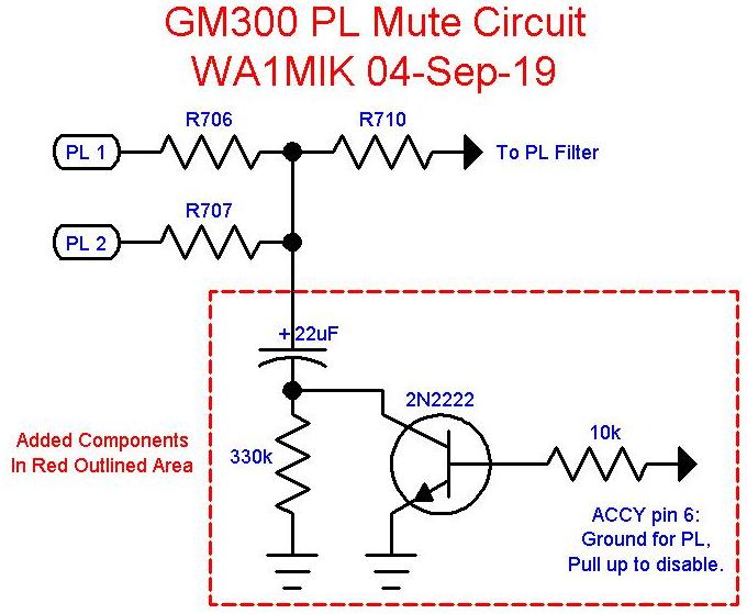
This same idea and circuit will work on a GM300 radio; it's just more difficult to find the resistor summing junction point. I found the junction of R706 and R707 to be convenient and right next to the microprocessor-area shield on the top of the enhanced logic board.
Trial and Error:
I tried several different methods with varying results. These are described below. The audio sections of the MaxTrac logic boards all operate on 9.6VDC and most of the signals ride along on a bias voltage of 4.8VDC. It's important to leave the DC voltage alone, because everything is DC-coupled, and a shift at one point will cause greater shifts elsewhere.
The radio was on the bench feeding a dummy load, with a deviation meter and frequency counter monitoring the transmitted signal.
You will eventually need the full schematic and parts layouts for your logic board. These are all in the scanned MaxTrac Detailed Service Manual section 2 of 4 that's posted elsewhere on this site. Here's a portion of the schematic so you can follow what we're doing. The microprocessor generates the PL and DPL signal via the two signals called PL1 and PL2 at the upper left corner. Click on the image for a larger view.
I first tried grounding the junction of R706 + R707, and R710. While this definitely muted the PL, it also resulted in a huge DC shift in the following transmit audio circuitry. This voltage shift caused the transmitted frequency to momentarily increase by several kHz, until the synthesizer could recover from the step on the REF MOD pin. A frequency counter registered nearly 3 kHz higher for one reading (10 readings per second) when this point was grounded. This is definitely an undesired side effect.
I really just wanted to kill the AC signal without changing the DC level, so I connected the positive lead of a 10uF 16V electrolytic capacitor to the junction of R706 + R707, and R710, and grounded the negative lead. This also initially caused a DC shift in the following circuitry until this capacitor charged. Once it had charged, however, no further shift was noticed. The PL was completely muted whenever the negative lead of the capacitor was grounded.
Realizing that I needed to pre-charge the capacitor to the existing DC voltage, I put a 330k resistor (this value is not critical) in series with the negative lead of the capacitor to ground. This charges the capacitor in about 10 seconds and lets the rest of the circuit operate normally. When this resistor is shorted out, thereby grounding the negative lead of the capacitor, the PL is muted, but no DC shift in the rest of the circuitry occurs. The transmit frequency only varies by 100 Hz when the circuit is activated or deactivated. I used a common small-signal NPN transistor to short out this resistor, however an FET or even a reed relay would also do the job.
Here is a summary of voltages measured at the logic board pin 13 (REF MOD) with 100.0 Hz PL. The REF MOD signal feeds the VCO on the RF board and is primarily used for low-frequency (i.e. PL and DPL) modulation linearity. The service manual specifies 4.3VDC and 0.78Vp-p as nominal voltages.
| Radio State | VDC | Vp-p | TX Freq Shift |
|---|---|---|---|
| Receive | 4.28 | 0.00 | |
| TX: NO Ground | 4.68 | 0.87 | |
| TX: DC Ground | 6.35 | 0.00 | >2 kHz |
| TX: AC Ground | 4.68 | 0.00 | <100 Hz |
The Actual Circuit:
The schematic diagram below represents the final circuit described above. The base of the transistor is grounded to enable transmit PL, and is allowed to float (or is pulled high) to disable transmit PL. I designed it this way because I was planning on using the repeater's COR signal (active-low) to control the transmitted PL: I wanted PL to be present when a signal was being received, causing the COR line to go low. The 1k resistor, in series with the base lead, is not critical, but it is necessary if active external circuitry is driving it. You may have to modify the input circuit of the transistor to suit your particular interfacing situation.
You can replace the NPN transistor with a PNP part. Reverse the emitter and collector leads. Grounding the base (through a required resistor) will disable PL; letting it float will allow PL to be transmitted.
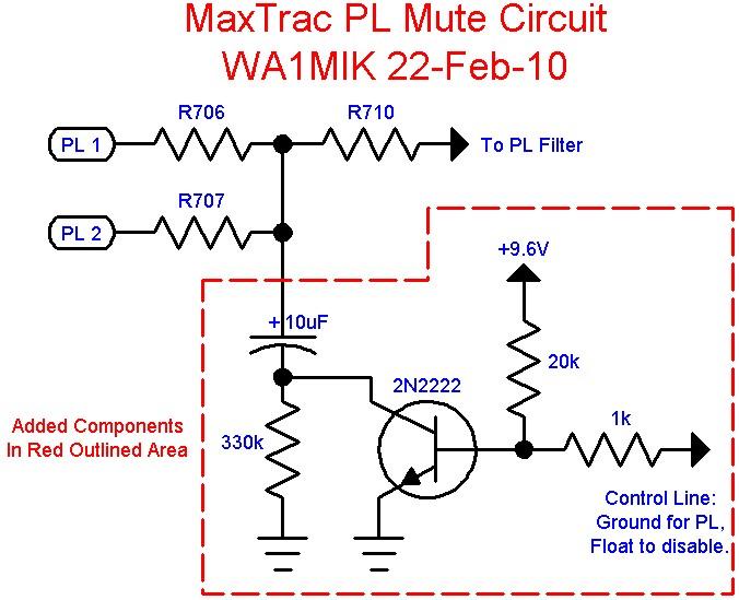
This circuit instantly mutes or passes the PL signal for transmission. There are no delays or glitches. There is no synchronization of the PL waveform, so it could be interrupted or resumed anywhere in the cycle.
Here's a photo of the GM300 16-channel (EPROM) logic board showing the connection points for R706/R707/R710, Ground, and the ACCY6 hole, which I decided to use for the TX PL MUTE input, active-high, so it mutes with no input signal from the associated equipment. Click on the photo for a larger view.
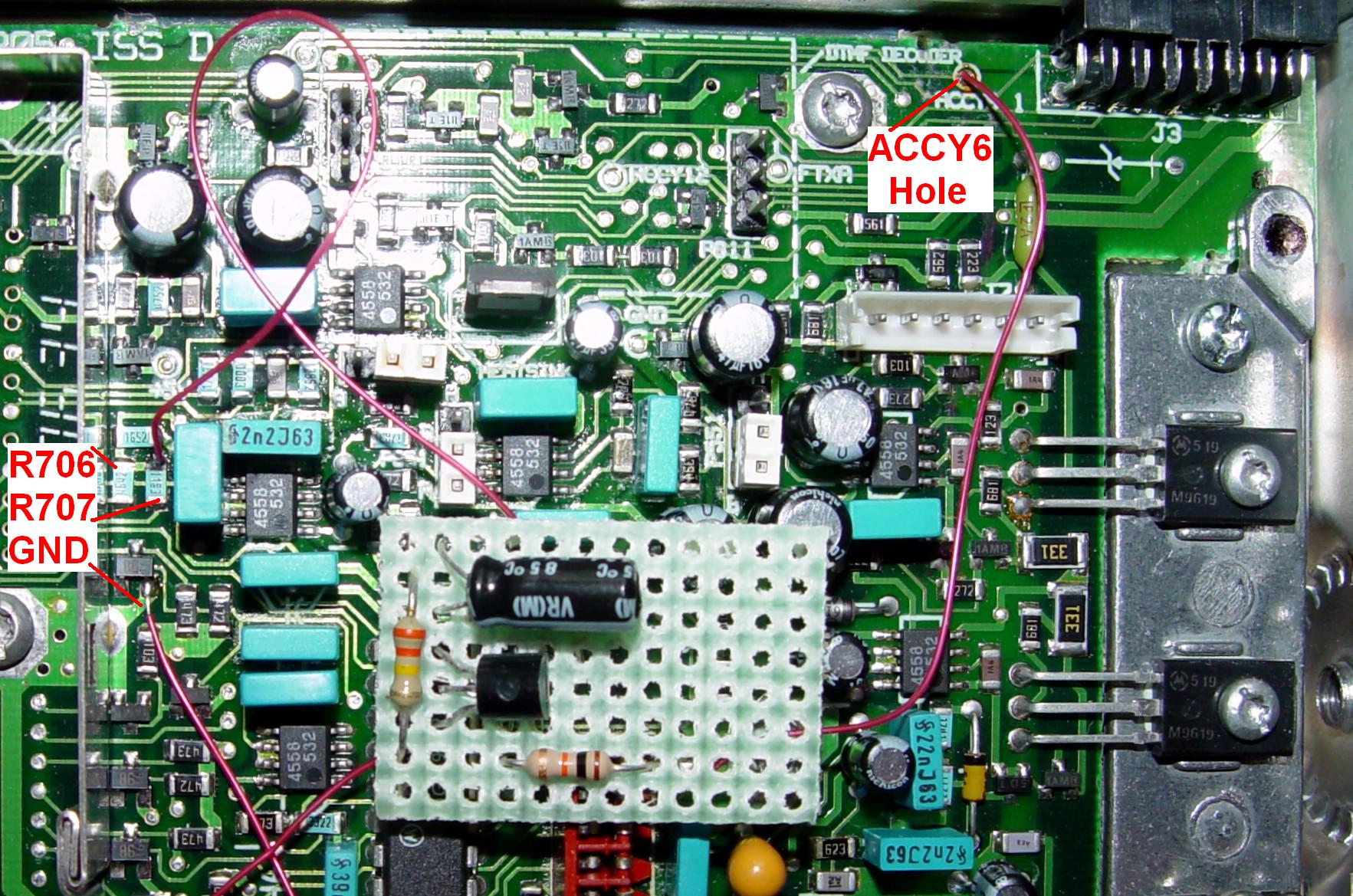
The circuit I used for the GM300 was a bit different as well. None of the parts values are really critical. ACCY6 already has a 4.7k pullup resistor on the logic board and the external equipment has an additional pullup; either is sufficient to fully turn the transistor on to mute the PL signal. Here's the schematic specifically for the GM300. Click on it for a larger view.
After I wired the mute circuit into the radio, I applied two layers of electrical tape, flipped it over, and positioned it above the white PA connector. It is held in place by the PA cable and the logic board shield.
Acknowledgements and Credits:
MaxTrac, GM300, PL, DPL, and lots of other terms are trademarks of Motorola, Inc.
Schematic information came from the MaxTrac Detailed Service Manual.
Contact Information:
The author can be contacted at: his-callsign [ at ] comcast [ dot ] net.
Back to the top of the page
Up one level (MaxTrac index)
Up two levels (Motorola index)
Back to Home
This page originally posted on Thursday 01-Jul-2010
Article text, artistic layout, and hand-coded HTML © Copyright 2010 by Robert W. Meister WA1MIK.
This web page, this web site, the information presented in and on its pages and in these modifications and conversions is © Copyrighted 1995 and (date of last update) by Kevin Custer W3KKC and multiple originating authors. All Rights Reserved, including that of paper and web publication elsewhere.