Motorola index
Back to Home
for the Motorola MaxTrac,
Radius, or GM300 Radios
By Robert W. Meister WA1MIK
|
MaxTrac index Motorola index Back to Home |
A Replacement Volume Control for the Motorola MaxTrac, Radius, or GM300 Radios By Robert W. Meister WA1MIK |
|
Background:
If you have a MaxTrac, Radius, or GM300 series radio that has no control of the volume, runs at full volume all the time, or turning the volume control has no effect or causes a huge jump in volume, then you have a common problem. All it takes is one hard bump on the volume control knob pushing the knob into the radio (like dropping the radio such that the volume control hits first, or if the knob gets pushed in during shipping). This motion pushes the entire knob and shaft assembly backwards. The shaft transfers the movement to the body of the pot, which moves backwards, the leads are held in place by being soldered into the PC board, and the phenolic with the resistive coating cracks and breaks just where the tabs go into the body of the pot. I took a broken pot apart and the exposed phenolic with the leads just fell into my hands. To test for this failure mode just measure the resistance of the resistor section from the high end to the low end. It's a 2k audio taper pot; if it reads open, you've found your problem. Another failure mode is where the wiper arm breaks off of the rotating plastic or the plastic disintegrates. You still get 2k from the high end to the low end but infinity from either end to the arm of the pot. No volume at all. There's no way to repair the broken pot.
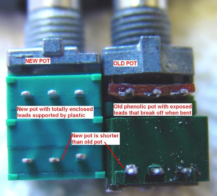
The photo below shows the new part on the left and the original part on the right. Note the phenolic pot on the old part, and the fully enclosed pot on the left. Also notice that the new part is about 1mm shorter than the old one, which is why it doesn't just drop in to the original circuit board holes.
The original MaxTrac volume control and power on/off switch (on the right in the photo above), part number 1880140M01, is no longer available from Motorola. The original part was made by ALPS of Japan. Motorola replaced that part with a newer one, which has a slightly different pin footprint and switch configuration. Motorola designed a new circuit board to accommodate this difference. They'll be glad to sell you the complete assembly, which consists of the microphone jack, volume control, circuit board, cable, and plug, for about $40 (for those that have not been inside a MaxTrac, the display section of the front panel is on a separate board). Note that the similar assembly for a 900 MHz MaxTrac has the HearClear (audio companding) module on it; it would cost considerably more to replace.
It seems silly to have to replace the entire front panel circuit board assembly when you can spend a little time and replace just the broken volume control and switch. I spoke with Motorola's Parts ID people and got the part number for the pot that goes on the new assembly. I then ordered some from Motorola, part number 1885724L01. At the time this article was written they cost $2.40 each, and there were plenty in stock. Incidentally, the new part is also made by ALPS.
Someone mentioned in June 2016 that he was having trouble locating the volume control. It seems that Motorola doesn't have them any more, and the suppliers I checked on the web were all out of stock. I called Motorola Parts ID; there is no replacement part. "That's All, Folks!" You could buy the entire VOL/MIC board for about $45 or rob the pot, the board, or the control head from another radio.
Why Are You Here?
Since the old part is no longer available, this article tells you how to deal with the new part. If your radio already has the new part or revised circuit board, you won't have to modify anything; just remove and replace the existing control.
The low band, high band UHF or 800 MHz radio uses the HLN5184 board but the 900 MHz radio uses the FLN5064 board since the 900 MHz radio has the HearClear audio companding circuitry.
Removal:
Remove the two control head screws using a T15 driver. Remove the volume control knob by pulling it off the shaft. Remove the single T10 screw and J-shaped clip holding the volume control circuit board into the rear of the control head. Remove the board and unplug it from the logic board connector. Unsolder the six terminals on the volume control and remove that component. It's broken anyway so it can be thrown away. Make sure the six solder holes are clean.
Note: The Motorola Radius and GM300 radios use the same volume control and can be modified the same way.
Modification:
On the HLN5184 board you'll have to drill three small holes to accommodate the size difference between the old pot (longer) and the new pot (shorter). Since the switch configuration is different, you'll need to add one short jumper wire when you solder in the new component. On the FLN5064 board, you need to take a bit more care when you drill the holes and add one more jumper. Follow the same instructions here but read the 900 MHz HearClear board section as well, as it adds an important step. The entire procedure should take about 15 minutes.
The new volume control is a bit shorter than the original. You can bend the leads and force them into the existing holes, but I didn't want to put that much stress on the new part. I figured out where the switch leads need to go and drilled new holes.
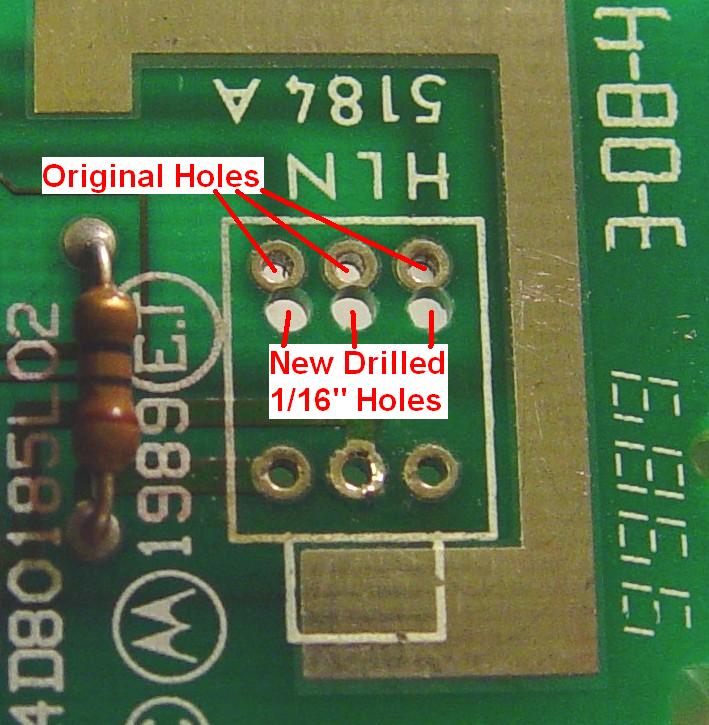
Using a 1/16-inch bit, drill three holes just in front of, and adjacent to, the existing switch holes. These are the ones toward the rear of the circuit board. See the photo below that shows their position. You can drill them from the top or the bottom.
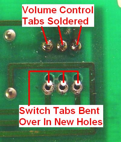
Insert the new volume control switch (rear section) leads into the three new holes and the pot (front section) leads into the three original holes towards the front of the circuit board. Make sure the control is oriented so it matches the outline on the board. All six leads should fit easily. Solder the three volume control pot leads - the ones closest the shaft. Bend the three switch leads, going through the newly drilled holes, back away from the shaft and onto the original plated holes. They will just reach. See the photo below that shows what it should look like.
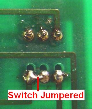
Insert a very short (about 1/4 inch) jumper wire (#22 wire or a short piece of a 1/4 watt resistor lead will do) into the original center and left switch holes (see the photo for "left" in this context), then solder the jumper wire, all three switch leads, and the holes they're touching. This jumper is necessary because the original switch used just the outer two terminals and was single-pole, single-throw. The new switch uses all three terminals and is single-pole, double-throw. The common lead is in the center, so when the switch is turned off, the center and left terminals make contact, and when the switch is turned on, the center and right terminals make contact. The jumper configures the switch to match the original functionality so the contact closure turns on the radio. The photo below shows the final product.
At this point you are done with your HLN5184 board and can jump ahead to "Reinstallation".
Modifying the 900 MHz HearClear Board:
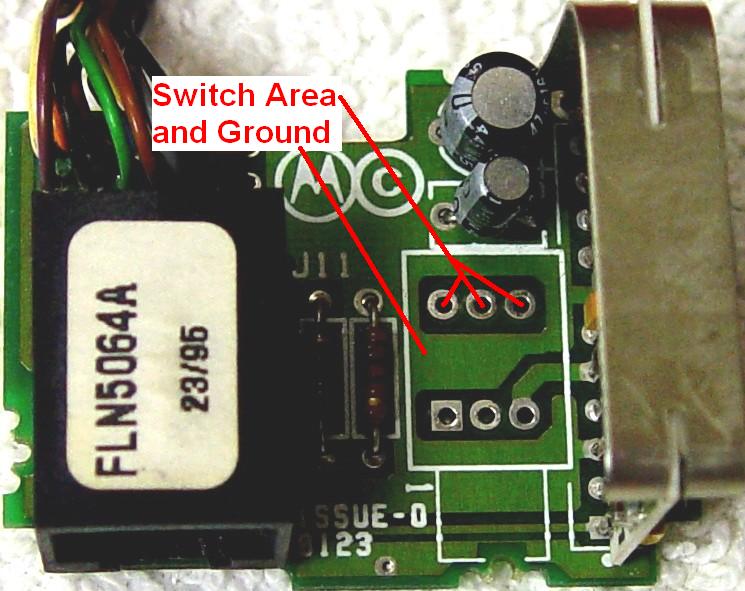
The basic procedure is the same as the non-HearClear board above, however this board, the FLN5064A, has different artwork. As such, the drilling of the three new holes for the switch needs to be done with a bit more care and closer to the existing solder holes. In fact, you want to cut into them rather than miss them entirely. This is due to limited space between the solder holes and some nearby traces. See the photo below for a top view of the HearClear board.
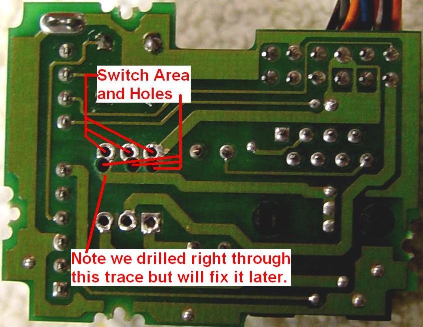
Note that one hole will have to go right through an existing trace, but it goes to the switch anyway and we can fix that. After drilling, the bottom looks like this:
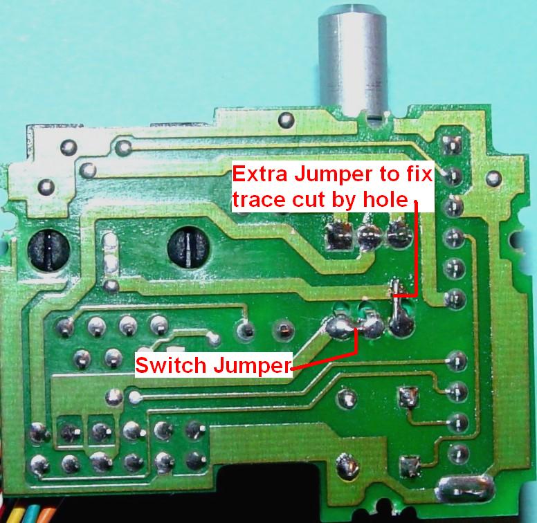
The procedure is otherwise the same as for the non-HearClear board. However, the hole you drill for the remaining switch lead will go right through the circuit board trace for that pad, so you will need to scrape some of the green solder mask off the trace and add one more short piece of wire from the right switch terminal to the trace on the other side of the hole. This can be seen in the photo below.
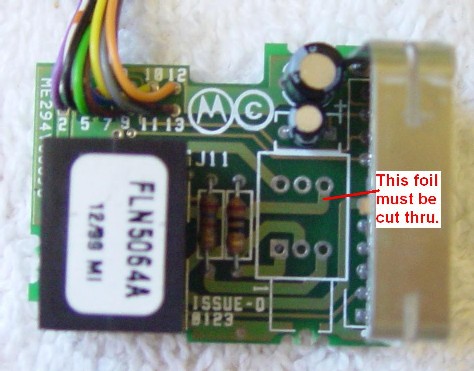
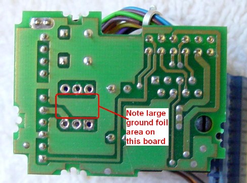
Naturally, just when you thought it was safe to jump into the water, Motorola comes along and changes things. I had to replace another broken volume control on a 900 MHz MaxTrac, so I extracted the old pot and prepared to drill three new holes to let the board accept the new pot. I discovered that even though the board has the same artwork and part numbers on it, they seem to have reversed the foil patterns. What used to be on the top is now on the bottom, and vice versa. I had to cut through one foil on the top, which ended up being covered by the new pot. I still had to add the jumpers under the board but one had to run all the way across the board to pick up the signal due to the cut foil. The photos below show this board before I drilled the holes.
Component-Side
Solder-Side
Reinstallation:
Slide the circuit board back into the front panel and secure it with its screw and J-shaped clamp. Before installing the control head, install the volume knob onto the new volume control. Support the control from the back as you push the knob onto the shaft; this will reduce stress on the component pins. Plug the cable back onto the logic board connector. Reinstall the control head with its two screws.
That's it. Enjoy your new functioning volume control.
Acknowledgements and Credits:
Thanks go to Scott KBØNLY for proofreading the article and finding a couple of mistakes - a rare occurrence indeed!
MaxTrac, Radius, GM300, HearClear and a bunch more are registered trademarks of Motorola, Inc. Circuit information for the MaxTrac radios was obtained from Motorola's official service manuals.
Contact Information:
The author can be reached at: his-callsign [ at ] comcast [ dot ] net.
Back to the top of the page
Maxtrac Index
Motorola index
Back to Home
This page originally posted 04-Jan-2006.
Article text, photos, and layout Copyright © 2006, 2010 by Robert W. Meister WA1MIK
This web page, this web site, the information presented in and on its pages and in these modifications and conversions is © Copyrighted 1995 and (date of last update) by Kevin Custer W3KKC and multiple originating authors. All Rights Reserved, including that of paper and web publication elsewhere.