Motorola index
Back to Home
By Robert W. Meister WA1MIK

|
MaxTrac index Motorola index Back to Home |
Spurious Outputs from MaxTrac Mobile Radios By Robert W. Meister WA1MIK |
|
Background:
I have read that the level of spurious output on Motorola MaxTrac mobile radios increases as the output power is decreased. Everyone, including myself, have been telling people that the MaxTrac mobile radios should never be run lower than one half to one third of their rated output power. Some radio models say they are continuously variable from some lower limit to their rated power; GM300 radios can be set to operate from 1-10 watts, 10-25 watts, or 25-45 watts depending on the model number.
I have been running a 45w UHF radio, set to about 5 watts output, as a driver for a 100w repeater amplifier for several years with no problems. I replaced it with a radio that had a manual power control pot. This gave me the opportunity to take a look at the purity of the output signal and either confirm or bust this myth. (In true Mythbuster's fashion, I put on my best Jamie Hyneman and Adam Savage outfits for this exercise.)
Typical Specifications:
Let's begin with specifications of several Motorola radios. These specs were obtained from service manuals in my library. Radius mobiles have the same ratings as MaxTracs. In the table below, the various columns have these meanings:
Band is the approximate operating band (LOW=25-50 MHz, HIGH=136-174 MHz,
UHF=403-512 MHz) or frequency of the radio in MHz.
Power is the rated output power of the radio in Watts.
dBc is the level of spurious and harmonic radiation below the carrier in dB.
| ||||||||||||||||||||||||||||||||||||||||||||||||||||||||||||||||||||||||||||||||||||||||||||||||||||||||||||||||||||||||
Note that portables exhibit the poorest spectral purity while base stations have the best numbers.
Test Setup:
I connected a 45 watt UHF Radius mobile radio (D44LRA7DA5CK) to an Astron RS12M power supply. The RF output went through a 2ft RG-58 cable to a Narda 30dB 50w DC-18 GHz coaxial attenuator. This was screwed into the RF input of an Agilent E4401B 1.5 GHz spectrum analyzer. A laptop computer, RIB, and appropriate cables allowed me to set the output power of the radio and transmit on the test frequency of 455.005 MHz. Initially I observed the entire spectrum from 9 kHz to 1.5 GHz, but after only seeing significant measurable signals at the first and second harmonics, I narrowed my investigation to the second harmonic only, at about 910 MHz. The third harmonic level was even lower, so I disregarded it. In theory, this plus higher harmonics would make up the entire spurious output signal amplitude.
The spectrum analyzer was set to a 10 kHz resolution bandwidth. Any narrower setting made the trace time too long to wait for. Even at this setting, a complete trace from 450 to 920 MHz took 6 seconds. The analyzer's peak search was used to locate the fundamental and second harmonic signals and get their dBm values.
I entered the Service section of the programming software and went directly to the transmitter output power adjustment screen. The RSS setting was 42 (for the UHF radio, 73 for the VHF-hi radio, 71 for the VHF-lo radio) when I started, because that was the value in the radio when it was in service at my repeater. (Note that the RSS value is NOT a percentage of power, or even a relative number. It's just a setting in the radio that affects the output power and can range from 0 to 255 depending on the software package. A higher number means more power, and that's all that can be inferred from the number itself.) I would set the slider pot to various levels, read the current on the power supply, and search for the peak level of the fundamental and second harmonic signals on the spectrum analyzer. These values were recorded and tabulated below.
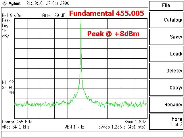
Here's a spectrum analyzer trace of the fundamental (carrier) frequency (455.005 MHz) with the radio at an RSS setting of 42:
I performed the same tests on a 25 watt VHF MaxTrac (D33MJA7DA5AK), because it was the only VHF radio I had around. Same test setup, similar results. Here's a spectrum analyzer trace of the fundamental (carrier) frequency (159.125 MHz) with the radio at an RSS setting of 35 (approximately 1 watt):
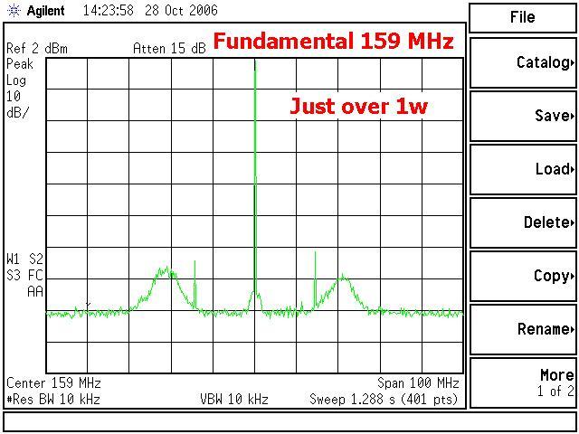
There's already a surprising amount of garbage around the carrier frequency. Not too much at the second harmonic (a bit more than the UHF radio), and nothing visible above that frequency.
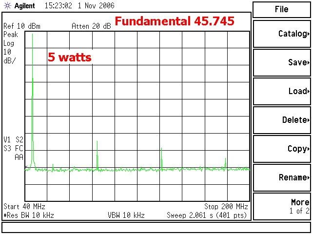
I tested a 42-50 MHz MaxTrac that had been tweaked to operate in the 50-54 MHz range. The test frequency was 45.745 MHz. The fundamental was clean, and there were no spurious outputs except the second harmonic.
Test Results:
Here's what this particular UHF transmitter was generating for its fundamental and second harmonic signals at various power levels. Explanations of the column titles are as follows:
RSS Value is the number on the RSS power setting screen.
Fund. dBm is the level of the fundamental (carrier) signal on the analyzer.
Harm. dBm is the level of the second harmonic (910 MHz) signal on the analyzer.
Harm. dBc is the level of the second harmonic signal below the fundamental signal.
Actual F. dBm is the actual fundamental output signal level of the radio in dBm
before the 30dB attenuator.
Actual Watts is the output power of the radio calculated from the Actual F. dBm value.
P. S. Amps is the current drawn by the radio when transmitting.
| |||||||||||||||||||||||||||||||||||||||||||||||||||||||||||||||||||||||||||||||||||||||||||
NOTE: Power pot settings less than 31 produced no RF output power at all. No values could be recorded.
In each case, the spurious output level of the second harmonic is at least 60dB below the carrier, which is the specification for a 40w Radius radio. The spurious output level did not necessarily rise by any significant amount just because the output power was set to an extremely low value.
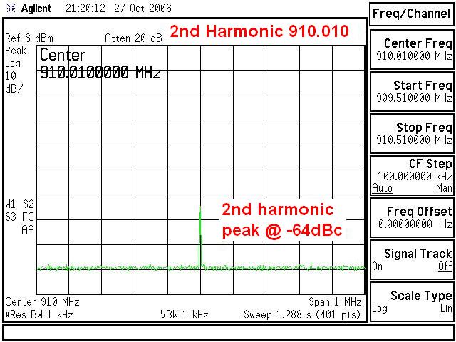
Here's a spectrum analyzer trace of the second harmonic (910.010 MHz). Nothing else has been changed except the analyzer's center frequency. You can see that this signal is more than 60dB below the top of the screen, which is where the carrier was peaked in the previous trace:
I recorded similar data on the 25 watt VHF MaxTrac, summarized below.
| ||||||||||||||||||||||||||||||||||||||||||||||||||||||||||||||||||||||||||||||||||||||||||||||||||
NOTE: Power pot settings less than 26 produced no RF output power at all. No values could be recorded.
In each case, the spurious output level of the second harmonic is at least 40dB below the carrier, which does not meet the specification of 57dBc for a 25w MaxTrac VHF radio. The spurious output level was certainly higher at lower output power settings, but it failed to meet the specs at any power setting.
A spectrum analyzer trace of the second harmonic (318.250 MHz) is similar to the one for UHF above.
I borrowed a 42-50 MHz MaxTrac that had been tweaked to operate in the 50-54 MHz range. Same test setup as above. At the test frequency of 45.745 MHz, I obtained the following data:
| ||||||||||||||||||||||||||||||||||||||||||||||||||||||||||||||||||||||||||||||||||||
NOTE: Power pot settings less than 31 produced no RF output power at all. No values could be recorded.
In each case, the spurious output level of the second harmonic is at least 60dB below the carrier, which is the specification for a low-band MaxTrac radio. There were some third and fourth harmonics present. The spurious output level did not necessarily rise by any significant amount just because the output power was set to an extremely low value. In fact, this radio exhibited quite a low level of spurious signal around 25 watts output. Here's the spectrum output at about 5 watts on the test frequency:
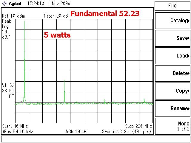
I ran additional tests on this low-band MaxTrac, because it had been modified to operate above the manufactured band limit. For this step, I adjusted the output power using RSS at its test frequency of 45.745 MHz, then transmitted on 52.23 MHz while viewing it on the spectrum analyzer. You can compare these readings to those in the table above.
| ||||||||||||||||||||||||||||||||||||||||||
There was considerably more harmonic energy, and in fact the third and fourth harmonics were clearly visible on the spectrum analyzer. Here's a spectrum output of the radio at 6 watts on 52.23 MHz:
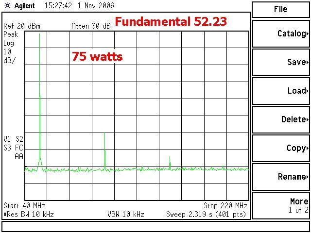
and the same radio after being set to 60 watts on the test frequency, 70 watts on 52.23 MHz:
Conclusions:
MaxTrac radios definitely get hot when transmitting. During my tests, the radio was never keyed up for more than 15 seconds every minute, yet the heat-sink and the coaxial attenuator were noticeably warm after the testing was completed.
My UHF radio did NOT generate excessive spurious emissions when its output power was reduced below one half (20 watts) to one third (13 watts) of its rated output power (40 watts). My VHF radio unfortunately failed at all power settings, but it did show more spurious emissions at lower power settings. The low-band MaxTrac performed like the UHF radio and managed to control its emissions quite admirably, however there was an increase in harmonic energy level in the ham-band.
Perhaps there's not as much truth to this myth as was expected. Remember (standard disclaimer), this was a test of my radio, and your radio may behave differently. And, of course, things are always "...slightly lower in California."
Credits and Acknowledgements:
"Mythbusters" is a television show produced by The Discovery Channel. Jamie and Adam are the show's hosts.
Motorola radio model names (and a lot of other terms) are all trademarks of Motorola, Inc.
All specifications came from official Motorola radio service manuals.
Thanks go to Dave N1OFJ, Mike WA6ILQ, and Scott KBØNLY who gave me suggestions for improving this article.
Dave N1OFJ loaned me his 60w low-band MaxTrac for this project, which he had previously tweaked to get full output in the 50-54 MHz segment of the band. Unfortunately the radio ceased transmitting just prior to these tests and needed a new logic board and a complete alignment to get it fully operational again. We think this was just coincidental and the problem never happened again.
No radios were modified, hurt, or injured in the process of conducting these tests.
Contact Information:
The author can be contacted at: his-callsign [ at ] comcast [ dot ] net.
Back to the top of the page
MaxTrac index
Motorola index
Back to Home
This page originally posted on Friday 27-Oct-2006
Images and article text © Copyright 2006 by Robert Meister WA1MIK.
Hand-coded HTML © Copyright 2006 by Robert Meister WA1MIK.
This web page, this web site, the information presented in and on its pages and in these modifications and conversions is © Copyrighted 1995 and (date of last update) by Kevin Custer W3KKC and multiple originating authors. All Rights Reserved, including that of paper and web publication elsewhere.