Back to Motorola Index
Back to Home
also known as a "Super Consolette"
plus a few other notes...
By Mike Morris WA6ILQ
|
Back to Mitrek index Back to Motorola Index Back to Home |
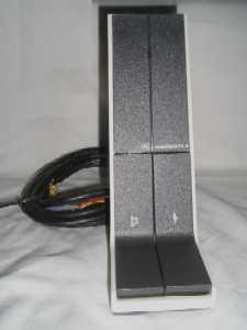
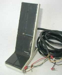
Interfacing the Mitrek Tabletop Base Station also known as a "Super Consolette" plus a few other notes... By Mike Morris WA6ILQ |
|
Comments and additional material are welcome
(even "Hey - you've got a typo at..." messages...
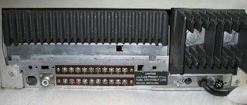
The photos above are of the back of a Mitrek Consolette base - the so-called JJB series. TB1 is on the top, TB2 is on the bottom.
Also in the above picture the cabinet lock is missing (the hole to the left of the SO-239 antenna connection), and there is a prepunched hole for a second antenna connector hiding behind the black "Caution" label - considering that the high band and UHF Mitrek mobiles will duplex in their case does that give you any ideas for a full duplex base station, or for a tabletop repeater?
The information on this web page is from the Mitrek "Super Consolette" tabletop base station manual 6881040E80-A. Note that you need the appropriate mobile manual (low band, high band, UHF, 800 MHz) to go along with it as the tabletop base is essentially a box that contains one of five different power supply chassis, a mobile radio chassis, volume and squelch controls, a frequency switch (if the unit was multifrequency), a speaker, and supporting components.
| ||||||||||||||||||||||||
Notes on the table above
| ||||||||||||||||||||||||
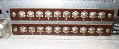
Normally to get a Mitrek tabletop base operational all you need to do is to jumper TB1-3 to TB2-4, and TB1-7 to TB1-8. Test the receiver by powering up, opening the squelch, and raising the volume up from zero to hear squelch noise. Tighten the squelch until it silences plus a little bit more. Test the PTT by attaching a dummy load and touching a clip lead from TB2-4 to TB2-5. If your station has PL or DPL the microphone will have a "Monitor" button that forces the audio mute off, and you can test that by touching a clip lead from TB2-4 to TB2-8. Connect a local microphone to TB2-4, TB2-5, TB2-6 and TB2-7. If your microphone has a monitor button connect the ungrounded side to TB2-8. Some microphones run both sides of the monitor button on two separate conductors and those will connect one side to to ground (TB2-4) and the other side to TB2-8.
In the upper picture the power supply chassis is on the right side, and the extra fuse holder hole required for the 220v version is to the left of the power cord (both sides of the AC mains have to be fused in a USA 220vAC environment). On some power supply chassis the extra fuse holder hole is not punched, in others it is punched and has a snap-in metal plug inserted.
There are four power supply subchassis used in the "Super Consolette":
Microphones:
Any of the following will work as a consolette base station microphone, be it Motrac,
Motran, Mocom-70, Syntor or Mitrek: The microphones listed below as "PL" have two
half-wide buttons, one for PTT and the other for PL / DPL defeat. The ones
listed as "CS" are intended for use on a carrier squelch base station and have either
a full width PTT button or a dummy monitor button and the half-wide PTT. A
two-button PL mic is shown in the left photo (it happens to be a TMN1632, but all the
2-button PL mics look pretty much the same), and a CS mic (a TMN-1004 with a dummy
left button is in the right photo.
The 04, 05, 12, 13, 14 and 15 micorphones are covered in the Mitrek Super-Consolette
manual listed above.
|
Using the consolette power supply to drive external
devices:
If I am going to add any external devices that are powered by the unit,
for example, a TNC, I always drill a hole to install a DC fuse
holder. Most fuse holders require a 1/2" hole... You can either
mount it in the top of the chassis, or you can use the small round
hole above the cabinet lock as a pilot hole for the drill bit, and an
on/off slide switch can be added into the adjacent prepunched holes if
you want (unless you have a lowband unit with the extender option - if
so there will already be a switch there to switch the extender on and
off, so if you want switched power you will have to do something else...
but on the other hand I've never seen a low band Mitrek that would
duplex inside the case).
Once the fuse holder is mounted, I jumper TB2-4 (ground) to TB2-9 and wire the fuse holder between TB2-1 and TB2-10, then I connect the external device to TB2-9 (external device ground) and TB2-10 (external device fused +12v power).
Yes, there is an extra pre-punched fuse holder hole in some of the power supply chassis. It was intended for use in the 220 or 240 volt versions of the supply but I don't like to use it. If you ever have to swap the power supply chassis for another one it's one more hassle that you have to take care of...
Another use for the fused external power is if you have a UHF tabletop repeater at your house and want to use a 2m mobile as a remote base. You could add a NHRC or ICS controller inside and a Kenwood TM-241 or similar radio outside.
If you use any of the spare terminal board screws - for powering a TNC or any other nonstandard uses, please do the next guy a favor and document your modifications - and leave a clear copy of your notes inside the chassis cover. I personally put the pages inside one clear page protector for every two single-sided sheets.
Good luck and after you get your Mitrek tabletop base going please drop an email to me and let me know how things went. Sometimes I wonder if anybody reads these missives to the masses...
Contact Information:
The author can be contacted at: his-callsign // at // repeater-builder // dot // com.
Back to the top of the page
Back to the Mitrek index
Back to the Motorola Index
Back to Home
Text, layout, photos and HTML are all Copyright © Michael R. Morris WA6ILQ 2004 and date of last update.
This article page first posted on 07-July-2004
If you see something above that is vague, missing (or outright wrong), please let me know! It's input from the readers that make these writeups better - I've probably either totally missed or shortchanged topics and /or subtopics that really need to be covered.
This web page, this web site, the information presented in and on its pages and in these modifications and conversions is © Copyrighted 1995 and (date of last update) by Kevin Custer W3KKC and multiple originating authors. All Rights Reserved, including that of paper and web publication elsewhere.