
Antenna Relay
The antenna relay is disabled to allow
the front RF connector to be the receiver port continuously. Cut the wires leading
from the board to the relay. Cut the coax, coming from the TX low-pass filter, at
the relay and fold it back toward the PA cavity. This coax will connect to a coax
connector installed at the left edge of the PA cavity.
Transmitter Output Connector
The transmitter output connector may
be a SO-239, type "N" or BNC. I mount mine on the sidewall of the PA cavity. It is
centered fore and aft and mounted as close as possible to the top of the sidewall. Make
sure it is not mounted so high that it interferes with the fit of the cover. A bulkhead
mount BNC would be ideal here since it is smaller than the SO-239 or "N". I have used
both "N" and SO-239 successfully. The coax that was cut loose from the antenna relay
is looped back and soldered to the connector.
Channel Element selection
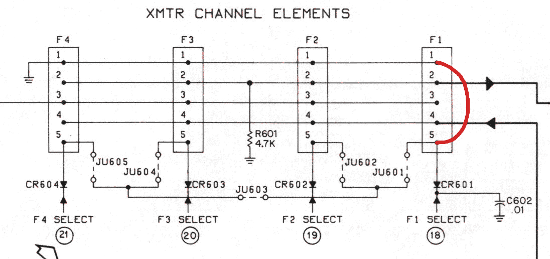
The channel elements are hard wired
on. You may use any of the four channel element sockets. I usually hard wire
number 1. On the receiver side jumper pin 1 to pin 4 of the socket. On the
transmitter side jumper pin 1 to pin 5 of the socket. This allows the frequency
select wires to be used for other purposes.


Receiver and audio PA mods
The receiver and audio PA must run
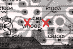
all the time in order for the radio to operate in full duplex. Cut diode CR1 to
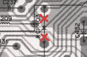
keep RX switched 9 volts on and disable speaker audio mute during transmit. Cut
diode CR403 to disable speaker mute by secondary PTT.
"Carrier Operated Switch",
(COS), output connection
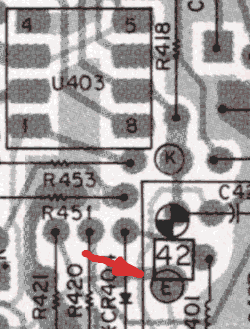
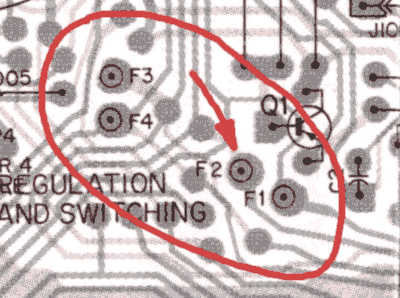
Connect a jumper betwen test point "E"
and test point "F2" to bring COS out the white wire. The F1, F2, F3 and F4 test points
are located at the front of the main board between, and slightly in front of, the receiver
and transmitter metering plugs. F1 through F4 are normally used for frequency
selection. Since we have hard-wired the channel element on, these wires are available
for other control functions. Test point "E" is located in front of U403, between
CR404 and L401.
If the radio is to be used with a Link-Comm Controller a buffer will be required between the COS output and the controller input due to the heavy loading imposed by the controller input circuitry.

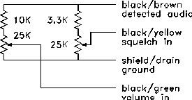
I use the simple circuit shown above. Power for this amplifier is supplied through the controller input which is internally pulled up to B+ with a resistor. You will also need to connect pots to control squelch and volume if the COS is used as input to the Link-Comm controller. Use circuit shown below. You may connect a speaker to the orange and green wires and monitor the activity. The squelch control will set the level at which the repeater will key up. If you are using a Palomar Controller or any other controller with built-in squelch controls you do not need this circuit.
Internally Mounted
PL Detectors
A PL detector module such as the
Comspec TS-64DS may be mounted inside the Mitrek radio. The input would go to
the detected audio output, pin 1 of C403A. The detected PL output logic level
would go to an unused frequency select lead test point (i.e. F1, which is the violet
wire in the cable).
Transmit Audio injection
To connect transmit audio from controller
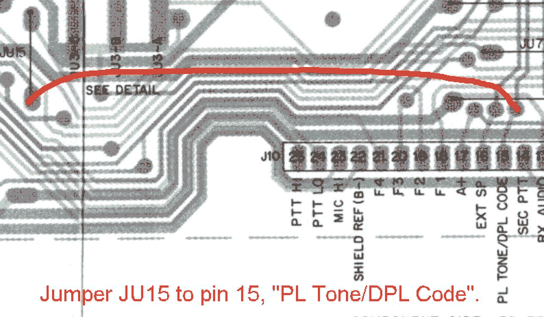
to transmitter, jumper "JU15", (labelled "L18" on some radios), to
pin 15 of the main board strip connector. This will connect TX audio to the PL/DPL
input of the TX modulator via the black/grey, (special use), wire. This bypasses the
speech amplifier and the equalization network which results in flat audio characteristics.
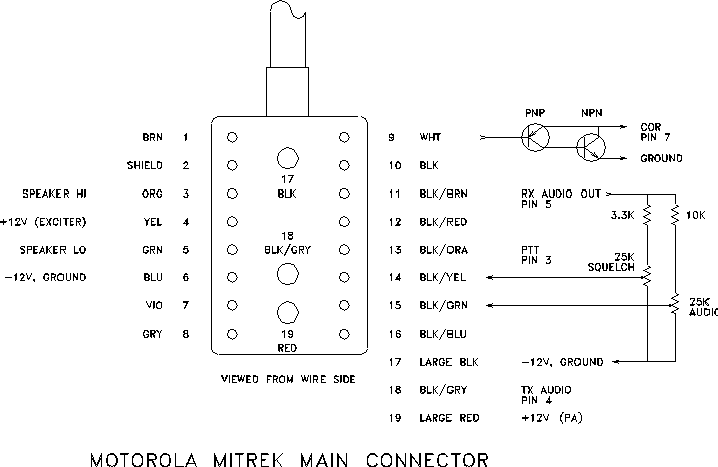
| Mitrek Cable wire color | Function | RLC2 Pin # |
| Black/Brown | Receive Audio | Pin 5 |
| Black/Grey | Transmit Audio | Pin 4 |
| Black/Orange | PTT | Pin 3 |
| White | COS | Pin 7 |
| Violet | Internal PL | Pin 2 |
| Large Black, Blue | Ground | Pin 8,9 |
Text copyright © Doug Spreng W7MCF 2000, 2004