Up two levels (Moto index)
Back to Home
to the 900 MHz
MSF5000 Repeater Station
By Mark Tomany N9WYS

|
Up one level (MSF index) Up two levels (Moto index) Back to Home |
Adding an Internal Duplexer to the 900 MHz MSF5000 Repeater Station By Mark Tomany N9WYS |
|
I needed to include a duplexer with my station, as split antennas were not a viable option to me. (There is insufficient spacing - both vertically and horizontally - at my site for two antennas.) The following was my method to resolving the dilemma.
First, I started scrounging for a duplexer. I ended up purchasing a TX-RX Model 28-88-0101. This is a four-cavity unit, and specifications are very similar - if not exact - to those of the Model 28-88-01A. Power handling was what I was looking for, but more importantly, it appeared as if the unit was physically small enough to fit within the rack/chassis of the MSF station. The seller was nice enough to tune it up for me for a nominal price, and also sent along some coax and connectors so I could cobble up some jumpers to make the "plumbing" run the way I needed it to at no extra charge! In order to begin installation, I had to disassemble the coax feeds coming in via the Station Control Panel. I had already removed the reference frequency cable and re-routed it for my installation of the HSO. So next were the input and output antenna connections.
The input was no big deal, and the nice thing is it had enough coax length on it to go nearly anywhere I needed it to. At first, my plan was to install the duplexer between the HSO drawer and the RF Tray. So I raised the RF Tray (not a small job in itself!) until it would just clear the underside of the Station Control Panel. Of course, the input antenna cable goes right to the RF Tray, so no problems with having enough cable there...
The Transmit cable connection is another story. Where it connects to the Station control panel, there is what appears to be an SWR reference device mounted. I believed that I needed to keep this item, so the question became how to do that? Leave it mounted and feed it after the duplexer? Move it and mount it to the duplexer at the TX input? Something else?
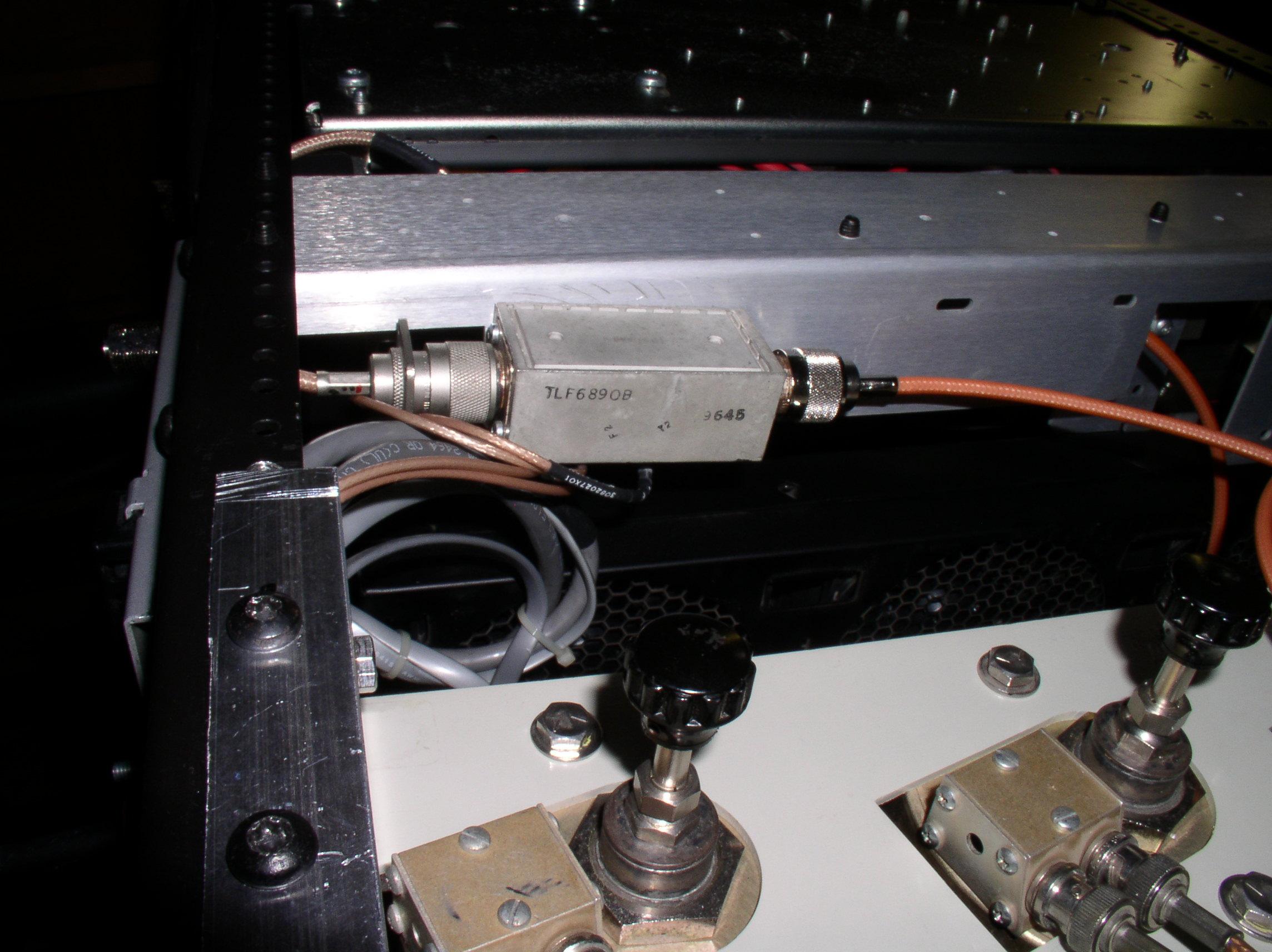
Well, it ended up being "something else"... What I eventually did was merely turn it around 180 degrees and mount it to the bottom of the aluminum angle bracket that was conveniently holding the circulator and reject load. I then connected my new jumper to the output of this device, and routed that to the TX input on the duplexer.
The RX feed was MUCH easier - all I need to do was change connectors (my duplexer has BNC connectors on its inputs) because the flange-mount N was just too large, even if I tried to use an inter-series (N-to-BNC) adapter. The output was an all new cable - N-male to flange mount N-female.
OK, I had all my cables ready... Now I try to fit the duplexer into the opening - ARRGH!! It wouldn't fit properly. I needed to raise the RF Tray another half an inch, but I didn't have that clearance available. So I decided to drop the RF Tray all the way down to the top of the HSO drawer (again, not an easy task) and see if "all that room" between the fan tray and the top of the RF Tray could be utilized. Unfortunately, the Station Control Panel becomes an issue, because there are interconnects on the inside of the panel, AND that nasty little AC power outlet. Yes, it is convenient when you need to power up your service monitor, but today it was giving me fits.
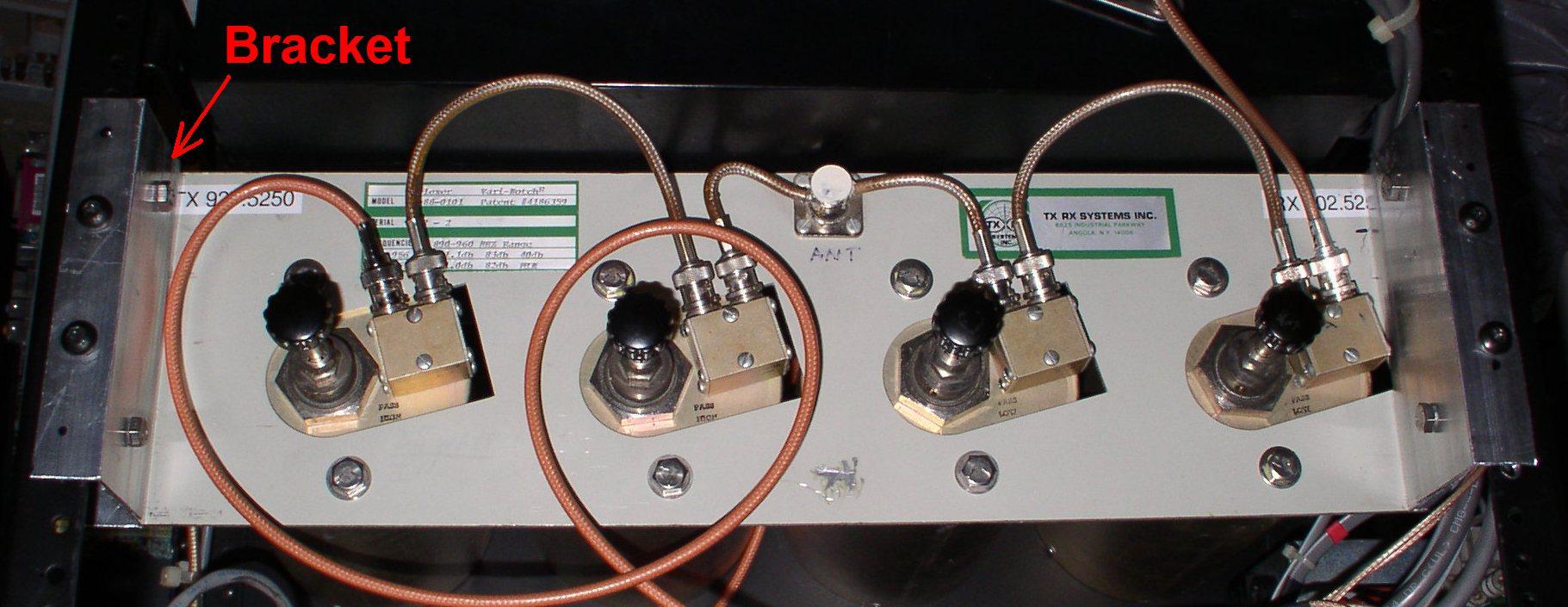
The next issue was how to get the entire duplexer to fit within the front and rear rails of the chassis/rack. This duplexer is small enough, depth-wise, to fit, but the tuning knobs/stems stick out from the front of the mounting panel, and the cavities themselves stick out from the back. I needed to fabricate some offset brackets.
Off I go to the local Ace Hardware and bought some 2" aluminum angle. I measured how far the tuning knobs stuck out from the front panel (2 - 3/8" on my duplexer) and started to make my brackets. I overlapped the two pieces of angle to give me the proper offset depth, then drilled and bolted them together. Next, I had to cut 1" off the "faces" of the brackets (where they mount to the duplexer and the chassis/rack). I now have my brackets, and the duplexer goes in quite nicely - although I had to mount the brackets first and then mouth the duplexer to the brackets.
I used the blank panel that was originally installed between the RF Tray and the HSO Drawer to cover up the view of the cavities from the front. Please note - I inserted my duplexer from the REAR because I had fewer clearance issues with the face panel of the duplexer and the Station Control Panel. Had I mounted this so the tuning rods could be accessed from the front, I would have needed to notch the face panel of the duplexer and one of my brackets.
In the end, the duplexer is mounted nicely within the station chassis/rack. This was a personal desire of mine - my other 900 MHz repeater has the cavities sticking out the front of the cabinet, and I believe this leaves them susceptible to damage (whether intentional or otherwise) and/or tampering. Plus, in order to facilitate that, I had to cut the door covering the station, again something I did not want to do on the MSF5000. This is a close-up view of the installation:
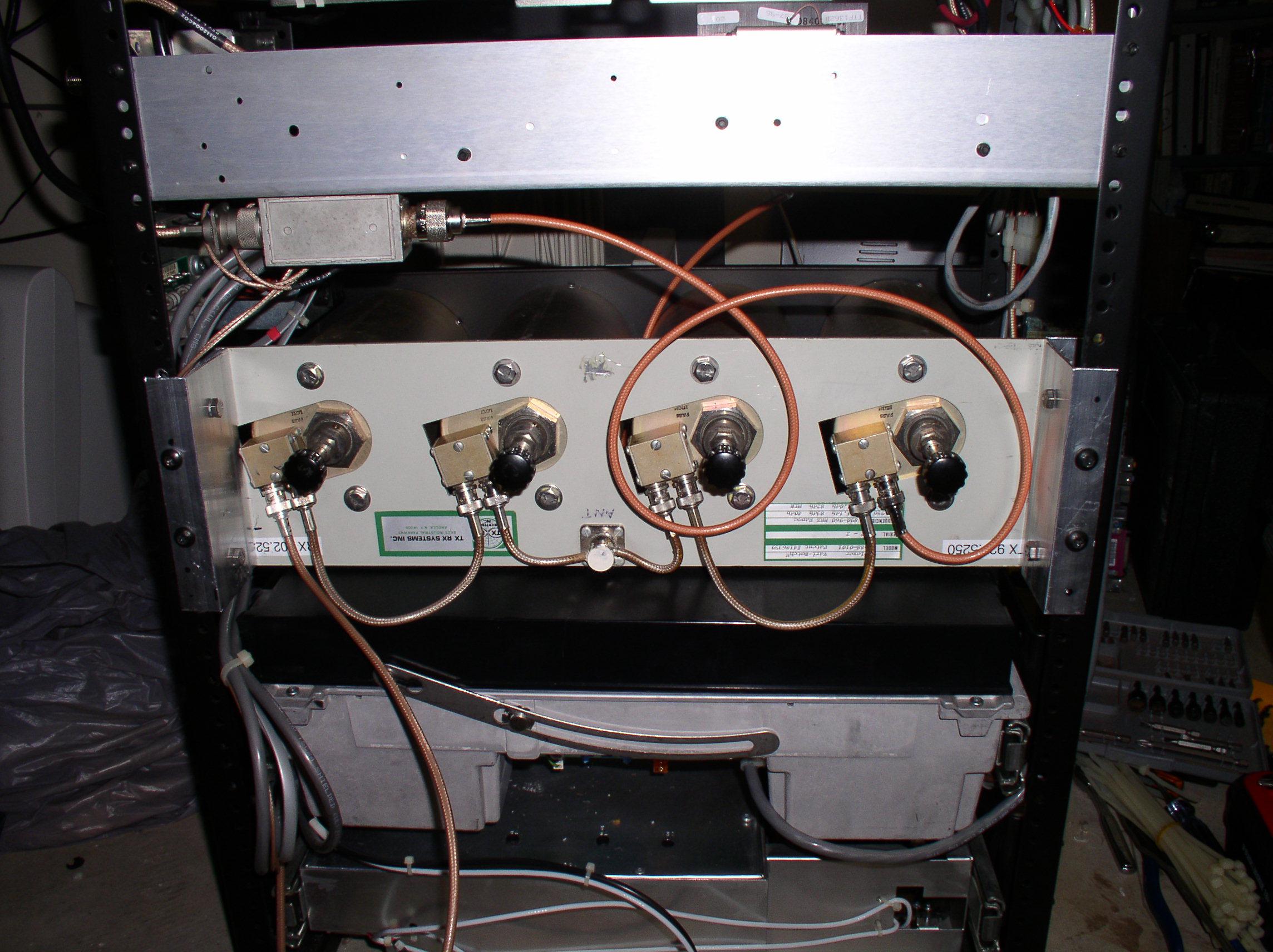
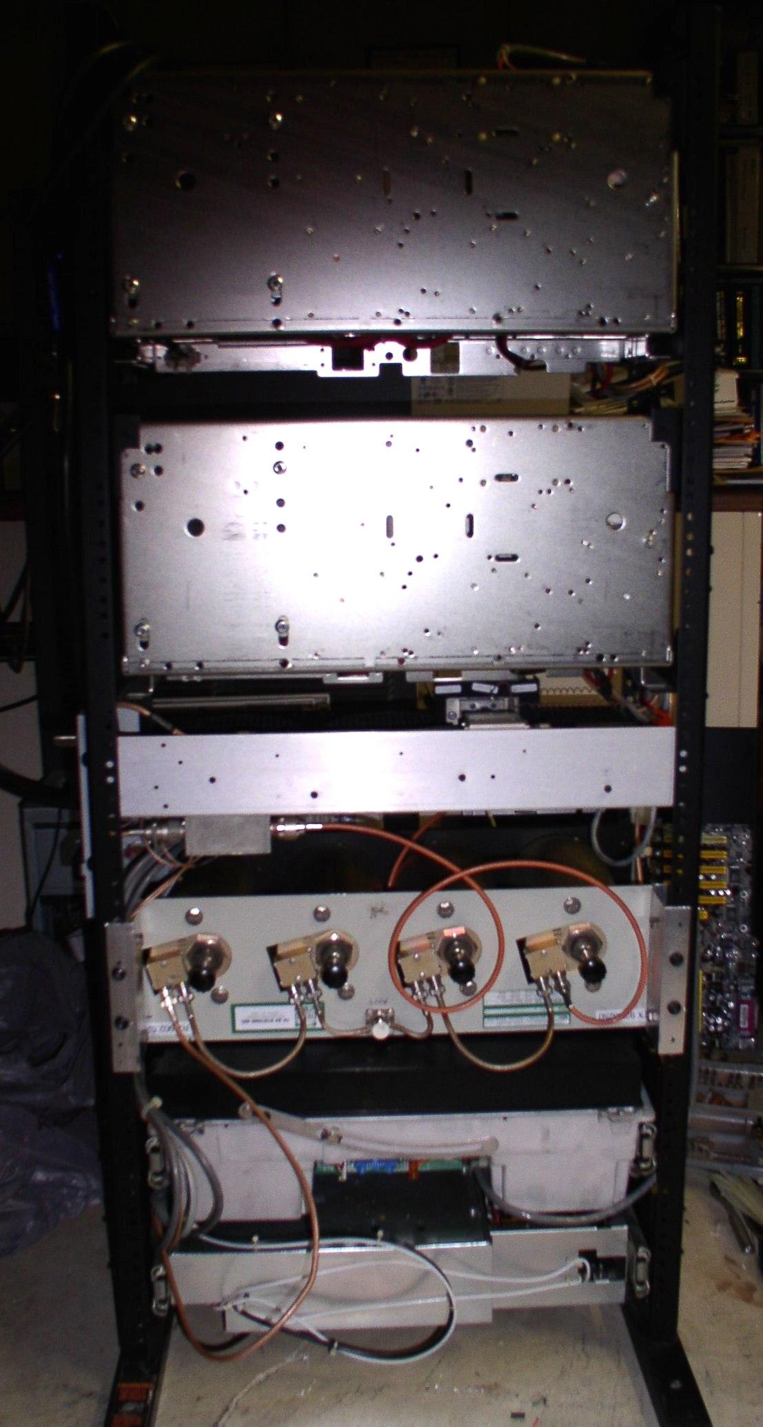
The following two photos show an overall view of the station, front and rear, with the duplexer in place:
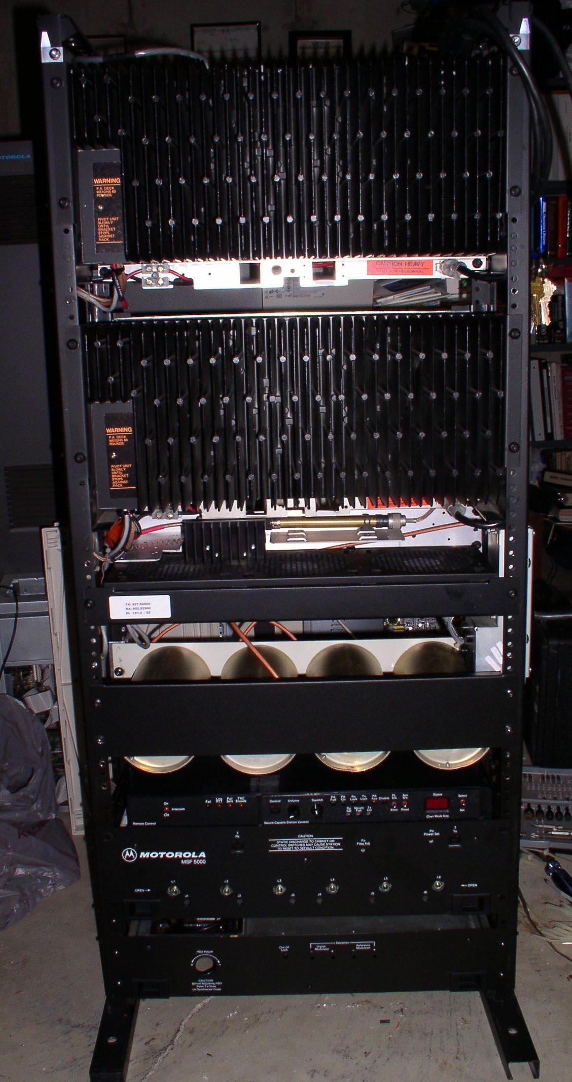
You will notice the "cover" is not on the station yet - I want to make absolutely certain that things are working properly before I put it all together. After all, it can be a real pain to find out I need to make a minor adjustment to the duplexer and then remember that in order to do so, I need to remove the entire cover skin...
My station originally measured about 120W output at the connection of the SWR detect device. After installation the duplexer, I read about 90W at the antenna output. I believe the manual calls for 85W for repeater station operations, so I think I'm in the ballpark, and if my math is right, this equates to about a 0.8 dB insertion loss due to the duplexer - acceptable to me.
I did notice that since the duplexer was installed, the repeater seemed to be prone to some "noise" - if I keyed the station with an on-frequency input signal, the station continued to output noise after that signal goes away. The resolution ended up being as simple as a slight "tightening" of the receiver and repeater squelch settings. (My meter panel showed both squelches "open", even though the station was not receiving any signal.) I increased the squelch settings until the Digital Metering Panel showed closed squelch, and the problem went away. However, the squelch settings are now pretty "tight" - working from memory, the receiver squelch is set at approx. "80" and the repeater squelch is at approx. "72", or vice versa. (OK, my memory isn't what it used to be...)
Now I find the station is cutting back on TX output power, and I think that problem lies in the cables I fabricated for the duplexer interconnection - specifically the duplexer output-to-antenna cable. The Female N-Type flange mount connector that is supposed to mount in the Station Control Panel became loose on the cable; rather than keep trying my own hand at this (and risk possible damage to the station PA's) I've ordered one.
So there are a few more tweaks that are necessary before this station is ready for "prime time"... but it's coming along nicely.
And MANY thanks to Bob WA1MIK for assisting me in getting this converted to HTML and published!
The author can be contacted at: n9wys [at] ameritech [dot] net.
Up one level (MSF index)
Up two levels (Moto index)
Back to Home
This article first posted 13-Apr-2008
Article text and all photos Copyright © 2008 by Mark A. Tomany N9WYS.
Hand-coded HTML Copyright © 2008 by Robert W. Meister WA1MIK.
Date of last update Copyright © 2008 by Mike Morris WA6ILQ.
This web page, this web site, the information presented in and on its pages and in these modifications and conversions is © Copyrighted 1995 and (date of last update) by Kevin Custer W3KKC and multiple originating authors. All Rights Reserved, including that of paper and web publication elsewhere.