Up two levels (Moto index)
Back to Home
to the MSF5000 Stations
By Robert W. Meister WA1MIK

|
Up one level (MSF index) Up two levels (Moto index) Back to Home |
Connecting Cooling Fans to the MSF5000 Stations By Robert W. Meister WA1MIK |
|
Several people have asked where to hook up cooling fans. Either their station had the fans and cable removed, or it never had them and the owners want to add them.
Some MSF stations were equipped with either AC or DC fans mounted in the empty space above the control tray and beneath the power amplifier(s). These one rack-unit fan trays could hold up to three fans. The AC fans are plugged into the accessory outlet on the inside of the station, at the back of the AC power junction box. I've only encountered 120V/60Hz fans, but I suspect 240V/50Hz fans were available in other markets.
DC fans need a source of 14VDC and that is obtained from the station's power supply. On those stations with just one power amplifier (PA) and one power supply (PS) behind it, that supply feeds the fan. On high-power stations with a driver PA/PS at the top of the cabinet and a final PA/PS below it, the fan connects to the final (lower) power supply.
I checked all of my service manuals. While many showed AC or DC fans in their cabling diagrams, none showed specifically where in the power supply these DC fans were connected. The power supply diagrams gave no hint either, so I looked into some of my stations to find out.
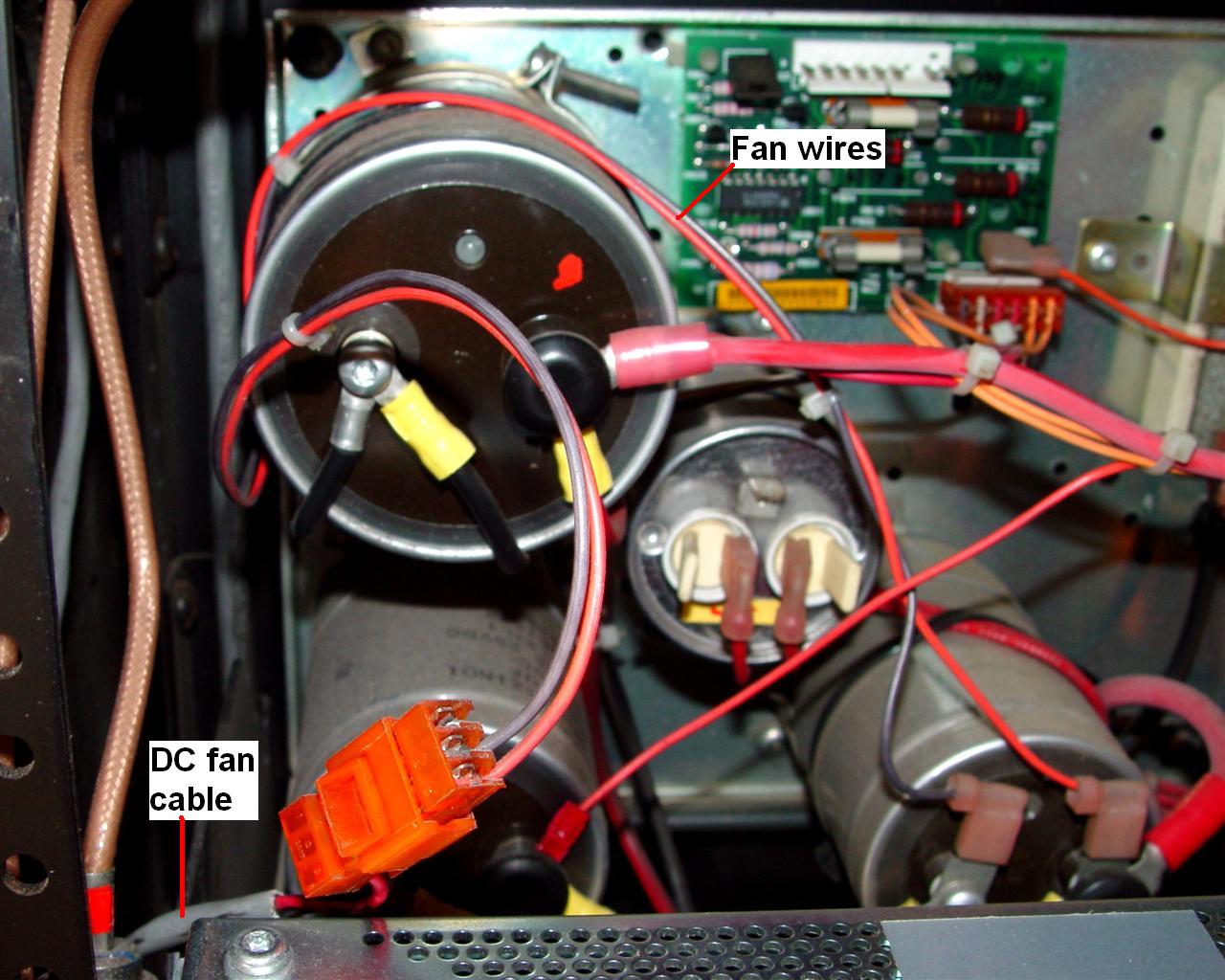
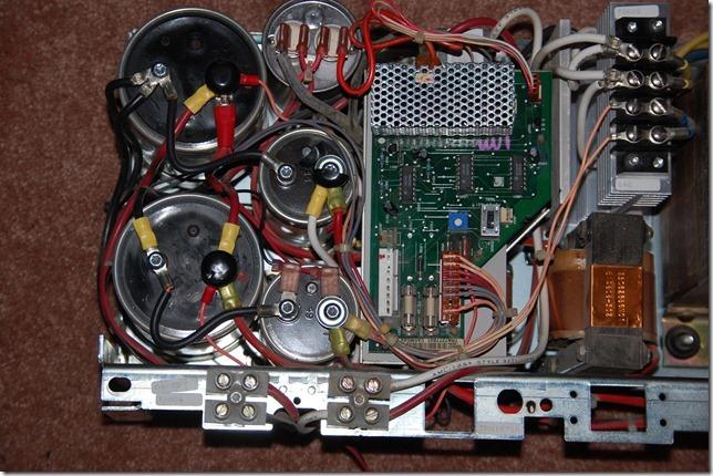
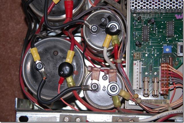
I flipped down the final PA of one of my 150w 896 MHz stations and soon found the pair of wires feeding the fan. They were connected via right-angle quick-disconnect terminals to C602, one of a pair of large aluminum electrolytic capacitors at the bottom left of the power supply assembly, shown below. Click on any of the images for a larger view.

These wires are secured to the capacitor at the upper left, then descend along the inside of the cabinet to the fan connector (pulled up to appear in the photo), shown below.
On my UHF stations that never had DC cooling fans, the quick-disconnect tabs are still present on C602, waiting for something to be attached. Note that this source is raw DC and not very well filtered. It is also un-fused, so be careful what you connect here. You could use it to power other accessories, although there are fused sources available elsewhere.
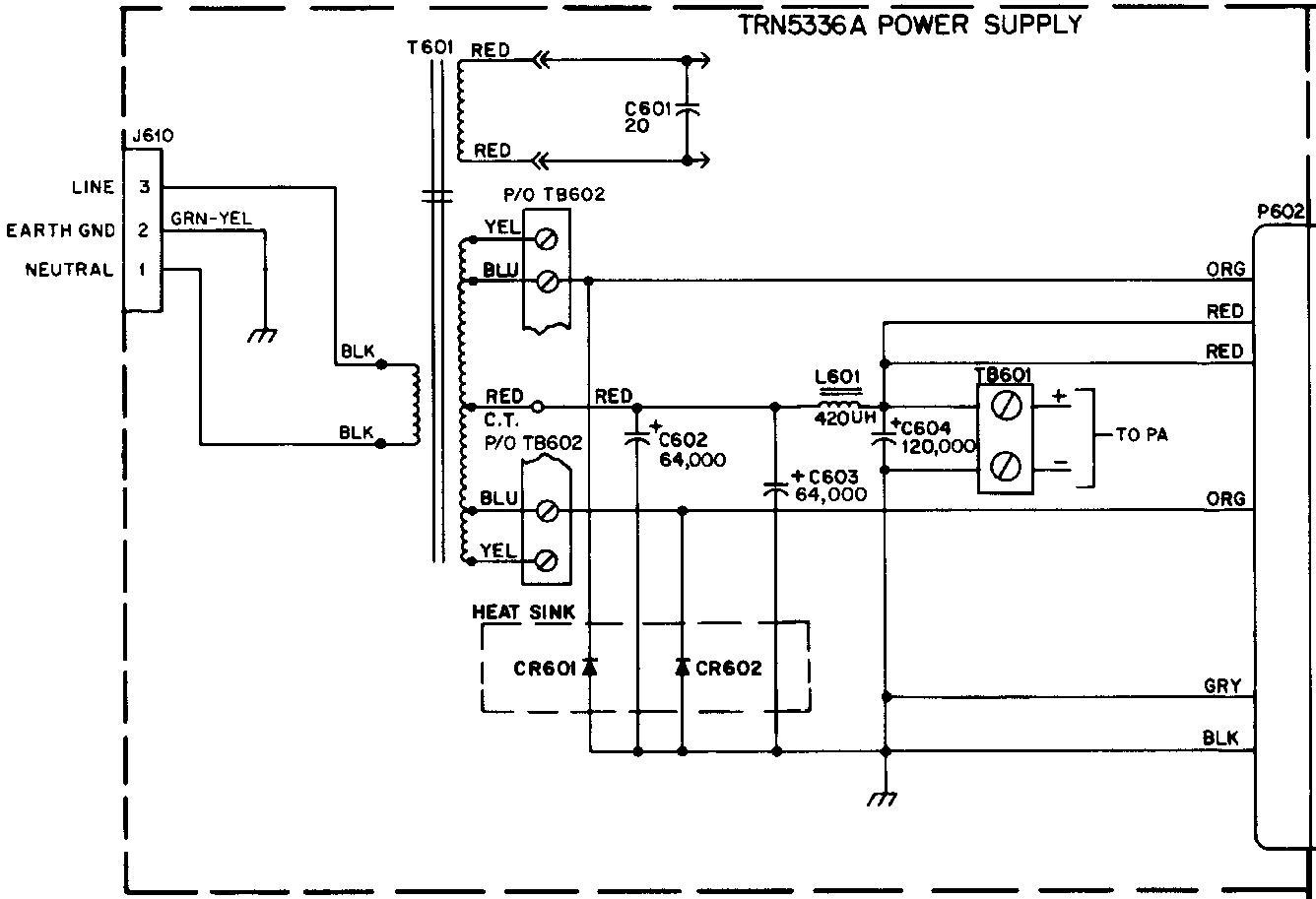
Here's a portion of the 14V power supply schematic . C602 is the first capacitor to the right of the power transformer. There's no indication of the quick-disconnect terminals on this component although some are mentioned in the parts list.
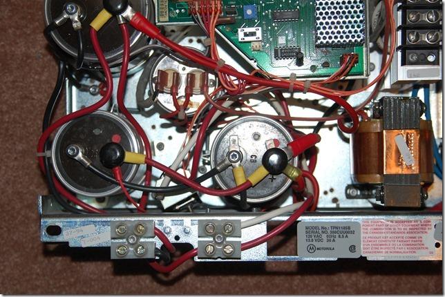
Bob VE3DJ supplied this photo of the fan terminals in a TPN1185B UHF battery-charging (14V only) power supply.
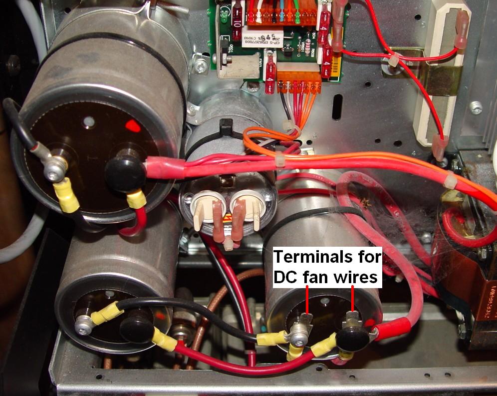
VHF stations use 28VDC for the power amplifiers, but there is still 14VDC floating around for the RF and Control trays. If you find the same capacitor with two unused tabs on it, measure the voltage first to make sure there's 14VDC on them, not 28VDC (unless your fan tray happens to have 28VDC fans in it). Bob VE3DJ supplied these photos of the fan terminals in a TPN1271B VHF battery-charging (28V/14V) power supply.
Here's a close-up of those terminals with the fan wires attached. There should be black plastic caps covering the positive terminals of all the power supply capacitors; some are missing or broken in these photos.
Contact Information:
The author can be contacted at: his-callsign [ at ] comcast [ dot ] net.
Photographs were taken by the author unless otherwise noted.
Up one level (MSF index)
Up two levels (Moto index)
Back to Home
This article first posted 03-Nov-2010.
This web page, this web site, the information presented in and on its pages and in these modifications and conversions is © Copyrighted 1995 and (date of last update) by Kevin Custer W3KKC and multiple originating authors. All Rights Reserved, including that of paper and web publication elsewhere.