Up two levels (Moto index)
Back to Home
Output to the
PURC5000 Link Receiver
By Robert W. Meister WA1MIK

|
Up one level (MSF index) Up two levels (Moto index) Back to Home |
Adding a Speaker Audio Output to the PURC5000 Link Receiver By Robert W. Meister WA1MIK |
|
Background:
I was given an audio/squelch (A/S) board (TRN6006) from a MICOR base station. Before considering plugging it into the link receiver chassis, I made sure the various signals on this board were the same as on the stock link receiver "flat" A/S board (TRN5363); they were. Be careful about using a MICOR MOBILE A/S board (TLN4310); the connections are different; these are documented in the table below.
Included with the A/S board was a TLN4290 audio PA board (the audio PA board from a mobile radio is the same). This small circuit board contains two resistors and two transistors mounted on a heat sink that bolts to the chassis. The audio PA board plugs into the A/S board and this makes it capable of providing 10 watts of audio power to a loudspeaker. Since the audio PA board is not present on the link receiver, I figured it was a simple matter to install it and mount it to the chassis.
I looked into what it would take to connect a volume control and loudspeaker to the link receiver, using either A/S board. The table below documents the available signals. It would seem that either board should work, but some modification will need to be done on the front panel circuit board.
| Pin | Base or Link Rx A/S Board | Front Panel | Mobile A/S Board |
|---|---|---|---|
| 1 | DPL Code Output | No Connection | Switched +9.6V |
| 2 | Discriminator Input from Rx | Same | Same |
| 3 | Output to Vol&Squ Controls | Same | Same |
| 4 | +9.6V | Same | Same |
| 5 | Intercom Hi | No Connection | Input from Volume Control |
| 6 | Ground | Same | Same |
| 7 | Preamp Output | Same | Mute (delayed) |
| 8 | Rx Unsquelched Indicator | Same | Same |
| 9 | Input from Squelch Control | Same | Same |
| 10 | PL Indicate | Same | Mute |
| 11 | Input from Volume Control | Ground [1] | No Connection |
| 12 | Channel Activity Indicator | No Connection | Same |
| 13 | PL Disable Input | Same | Same |
| 14 | Keyed A+ to PL/DPL Board | No Connection | Time-out Tone Input |
| 15 | Audio PA A- | Ground | Same |
| 16 | Audio PA A+ | A+ | Same |
| 17 | Speaker Output High | No Connection | Same |
| 18 | Speaker Output Low | No Connection | Same |
The following items will need to be done to complete the modification:
In the mobile radio, the volume and squelch controls are both 25k pots, they have 3.3k resistors in series with the high ends, and they get their signal from the buffered emitter follower audio (A/S board pin 3). The arm of the squelch pot goes back into the A/S board on pin 9. (The link receiver has the squelch pot on the front panel.) The arm of the volume control goes back into the A/S board on pin 11. (You can use 50k pots instead. The value is not critical. You'll have smoother operation with audio taper pots than with linear pots.)
The emitter follower audio is unsquelched. The link receiver was never meant to have a squelched audio amplifier in it, and the squelch circuit is incapable of fully muting the audio. The volume control needs muted audio, which is only available on the front panel circuit board, and it must have a capacitor in series to remove the DC voltage. Unfortunately this audio is also level-controlled by the line level pot on the A/S board.
Due to the increased power requirement, the audio amplifier power (pins 15 and 16) and speaker audio (pins 17 and 18) will be run to a new terminal strip to be mounted on the back of the link receiver chassis.
Modification Steps:
Click on any of the photos or images for a larger view.
Hardware modification consists of mounting the audio PA board and terminal strip to the rear of the chassis, and mounting the volume control to the front of the chassis.
Remove the top cover, front plate, and front/bottom chassis. Remove both of the snap-in shields. Remove all of the circuit boards from the chassis. This just makes it a lot easier to work with.
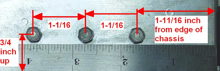
Drill holes in the back of the chassis and mount the audio PA. See the hole location measurements photo below. The original hardware was #10-32 but I drilled 7/32 inch holes in the chassis to allow for movement of the audio PA so I could align it properly with the A/S board. I removed all burrs on the inside of the chassis. A piece of 1/8-inch thick aluminum came with the audio PA board and acts as a spacer between the inside of the chassis and the board. Heat sink thermal compound was spread all over the metal pieces when I got them; I cleaned all of this off and did not add any when I mounted the audio PA to the chassis because I was in a hurry to see if it would work. You should spread some on all mating surfaces before finalizing the assembly.
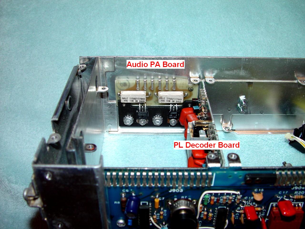
Here's the audio PA board mounted on the rear of the chassis. The original DPL decoder board has been replaced with a PL decoder board.
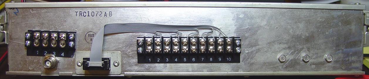
Drill holes in the back of the chassis and mount the four-position terminal block. On the back of the chassis, I had previously mounted a 10-position terminal block that is wired to the receiver's main I/O connector. I added a numbering strip to it when I added the speaker amplifier. The new 4-position terminal block was mounted above the antenna jack. (Yes, it's crooked. I didn't center-punch the holes and the drill bit wandered all over the place. Dull drill bits will do that.) Use the shortest screws you can. Cut them flush with the nuts if necessary. If they extend into the chassis too far, some of them will hit the coil shields on the low- and mid-band receivers. (I had to shorten the two closest to the middle of the chassis.) I also discovered that these coil shields can touch the terminal lugs that stick through the holes; I had to cover them with a few pieces of electrical tape. They could be cut a bit shorter or you might consider moving the terminal block slightly where nothing else can hit it.
Drill holes in the front/bottom chassis plate and mount the volume control to the left of the metering jack. I centered it vertically so it lined up with the metering jack. I checked for interference behind the front panel before choosing where to mount the pot. There's plenty of clearance in several areas for commonly available controls.
Drill a hole in the black front plate to clear the volume control's mounting nut.
Electrical modifications consist of wiring the terminal strip to the front panel board, modifying the squelch circuit on the A/S board, and wiring the front panel volume control to the front panel board.
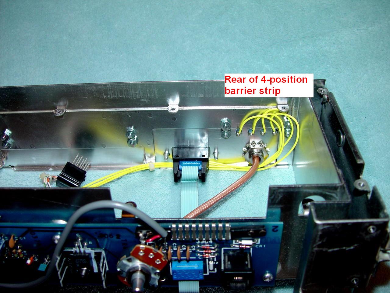
Add wires from the back of the front panel circuit board A/S pins 15, 16, 17, and 18 to the new terminal block. See the photo above. I used #20 wire between the new terminal block and the A/S connector on the front panel circuit board. It was wired according to the table below. Route these between the bottom chassis and the front panel along side the metering extension cable. Leave enough slack so they don't interfere with the receiver.
| # | Signal Name | Where It Goes |
|---|---|---|
| 1 | A- (Ground) | Front Panel A/S pin 15 |
| 2 | A+ (+14VDC) | Front Panel A/S pin 16 |
| 3 | Speaker High | Front Panel A/S pin 17 |
| 4 | Speaker Low | Front Panel A/S pin 18 |
Here's the inside wiring of the four-position Cinch 140-series terminal block. I used lugs specifically made for it. I placed Teflon sleeves over the lugs so they wouldn't short out against the edges of the holes. I used 20 gauge Teflon insulated stranded wire.
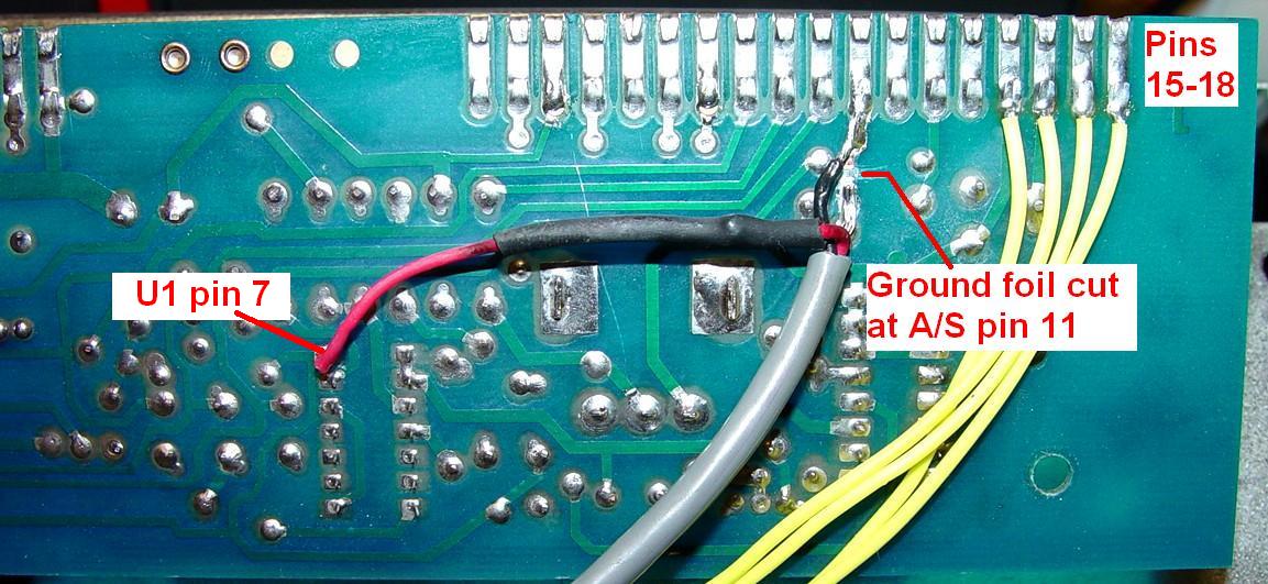
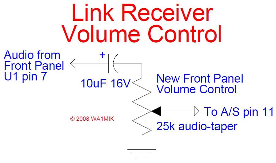
On the back of the front panel circuit board, isolate A/S pin 11 from ground by cutting the foil where indicated. Add wires to the back of the front panel circuit board to reach the volume control. See the photo below. Mount the volume control to the front panel. The volume potentiometer (25k audio-taper) was wired using a piece of two-conductor shielded wire with a 10uF capacitor in series with the top (clockwise end) of the pot. The signal feeding it comes from the front panel's U1 pin 7. The arm of the pot goes to the A/S connector pin 11. The bottom (counter-clockwise end) of the pot goes to ground - the foil that was originally connected to A/S pin 11 - via the shield lead.
Here's a schematic diagram of the volume control components:
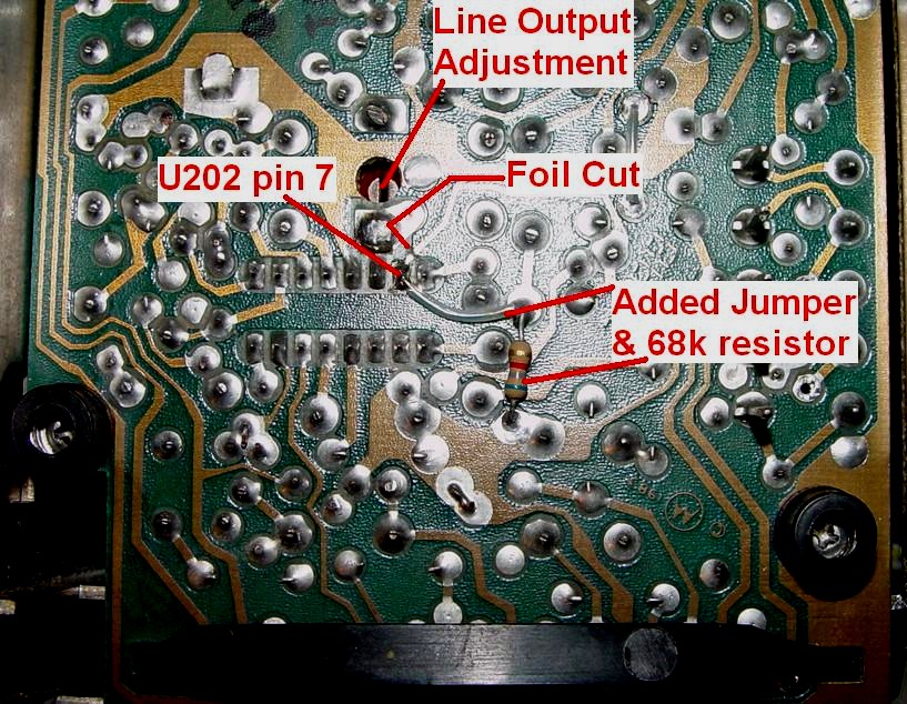
I had to modify the A/S board to improve the squelch muting. Cut the foil leaving the squelch chip U202 pin 7. Add an insulated jumper wire from U202 pin 7 to the vacant hole next to C213. Add a 68k resistor from this same point to a nearby vacant ground hole. Here's a photo of the modified board. Astute viewers may note that the resistor is actually a 6.8k; I have since replaced it with a 68k but it didn't affect the board's operation.
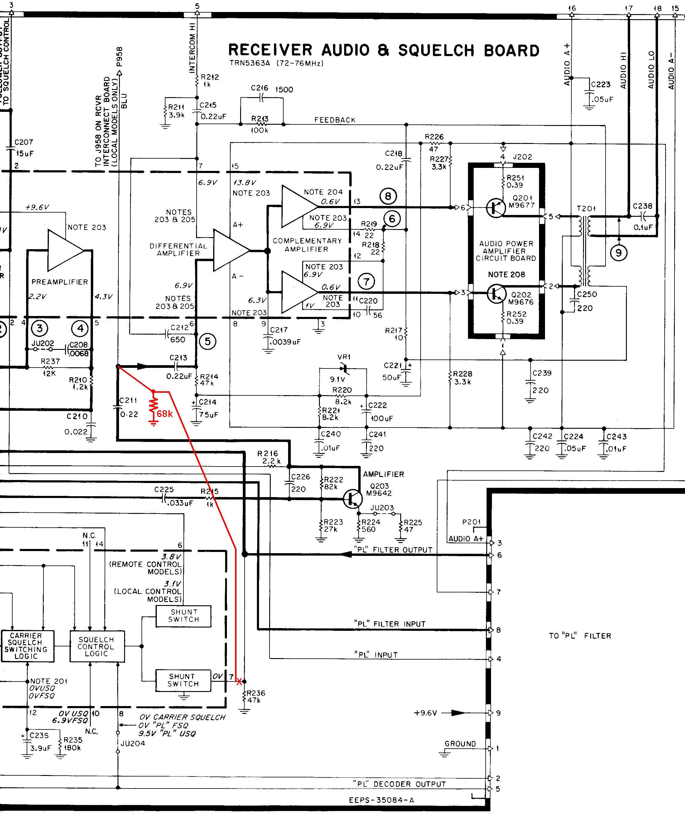
Here's a segment of the schematic showing the A/S modification:
Replace all of the circuit boards in the chassis. Reinstall both of the snap-in shields. Replace the front/bottom chassis, front plate, and top cover. Install a knob on the volume control. Label the front panel if you wish.
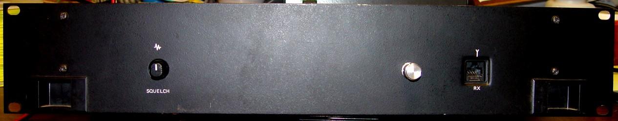
The front panel now sports a new (still unlabeled) volume control. I'd rather have a larger knob so it covers the mounting nut, which is visible in the bigger hole in the panel.
Results:
The audio PA requires significantly more input power than the stock link receiver. At the minimum volume setting, it now draws 350 mA. At maximum output with a fully deviated sinusoidal input signal, the chassis draws over 3.5 amps. I measured 15 VAC across an 8 ohm dummy load at full volume; this corresponds to 25 watts. Even at 11 VAC output (15 watts), distortion was just becoming visible on an oscilloscope and measured less than 3%.
The amplifier didn't do as well with a 4 ohm dummy load. Distortion was already over 3% at 5 VAC output (6.25 watts). The maximum output was 9 VAC (20.25 watts). It would seem that this audio amplifier is happier when feeding an 8 ohm loudspeaker.
The minimum volume setting is zero, i.e. no sound at all. You could add a 100 ohm resistor between the low end of the volume control and ground to give you just a bit of audio even at the minimum setting. If you do this, make sure the receiver won't be sitting around at a quiet location where audio could be heard by those who don't need/want to hear it.
If you buy a new volume control, consider getting one with a power switch on it. You can wire this in series with the A+ signal (A/S board pin 16) and turn the audio PA power off when you don't need it, reducing the power consumption to 180 mA. This is especially useful if the receiver will be at a solar-powered site where electricity is at a premium. Just make sure you locate the control where there's adequate clearance between it and the front panel components. Optionally you could drill holes for a mini SPST toggle switch.
Due to the higher current requirement, DC power is now fed in via the new four-position terminal strip rather than the 10-position terminal strip and main I/O connector.
When I first did this conversion, I had some residual noise feed-through when the receiver was squelched. This was only 5-10 millivolts and was independent of the volume control setting, but it was enough to be heard in the loudspeaker. With a full-quieting input signal, the noise went away. I traced it through to Q203 on the A/S board, which amplified the noise. I modified the board to deal with it (U202 pin 7) and added this to the procedure. Now the speaker output is absolutely quiet when the receiver is squelched up. Remember, the stock TRN5363 A/S board has no de-emphasis, so the signal heard in the speaker won't sound normal. A few components that are different between the TRN5363 and the TRN6006 deal with de-emphasis and will be the subject of another article.
Depending on your intended use, you could add a PL Enable/Disable switch and even a few LEDs to the front panel, to indicate Power On, PL/DPL Detected, Squelch Open, etc.
Parts Used:
| Description | Mouser P/N |
|---|---|
| 25k audio-taper 16mm potentiometer | 313-1500F-25K |
| 4-position Cinch 140-series terminal block | 538-4140 |
| 4-position Cinch 140-series numbering strip | 538-MS4140 |
| Four (4) Cinch 140-series terminal lugs | 538-Y140 |
| 10uF 16V capacitor | My own stock |
| 68k 1/4w resistor | My own stock |
Mouser also has the matching Cinch 140-series 10-position terminal blocks and numbering strips, p/n 538-10140 and 538-MS10140.
Acknowledgements and Credits:
Schematics and circuit board layouts came from the PURC5000 Link Receiver Options manual, p/n 6881064E10. Additional wiring and A/S board info came from a MICOR VHF Mobile Instruction Manual, 6881008E40 and a MICOR UHF Base/Repeater Station Instruction Manual, 6881025E50.
All photos were taken by the author and are copyright by him.
Contact Information:
The author can be contacted at: his-callsign [ at ] comcast [ dot ] net.
Article text, photographs, and hand-coded HTML © Copyright 2008 By Robert W. Meister WA1MIK.
Up one level (MSF index)
Up two levels (Moto index)
Back to Home
This article first posted 21-Nov-2008
This web page, this web site, the information presented in and on its pages and in these modifications and conversions is © Copyrighted 1995 and (date of last update) by Kevin Custer W3KKC and multiple originating authors. All Rights Reserved, including that of paper and web publication elsewhere.