Up two levels (Moto index)
Back to Home
Converting a New Jersey
900 MHz MSF5000
for Amateur Band use
By Mark Tomany N9WYS
with input from Jim McLaughlin W9JEM

|
Up one level (MSF index) Up two levels (Moto index) Back to Home |
Another User Experience: Converting a New Jersey 900 MHz MSF5000 for Amateur Band use By Mark Tomany N9WYS with input from Jim McLaughlin W9JEM |
|
Other articles have been written about converting a 900 MHz Motorola MSF5000 station for use on the Amateur portion of the band. This article, although it may contain some "re-hashing" of earlier information, is my attempt to describe the trials and tribulations of two Chicago-area hams as they converted two of these stations over to Amateur use. Forgive me if I ramble from time to time; I'm merely trying to give you the full experience. The stations I will refer to in this article are the model C85GFB5203AT, a digital-capable station, commonly referred to as an "Analog-Plus 896 MHz" station.
We're on the road:
Our odyssey started with the mention on the BatLabs BatBoard (discussion group) about the possibility of some 900 MHz MSF5000 stations possibly becoming available from a utility company in New Jersey. The discussion continued for nearly a year (and involved the originator of the information being deployed overseas) before the deal started coming together. I believe there were about 10 or 12 of us collectively that had expressed an interest in these stations. Our mediator, now "out-of-the-loop", referred us to the utility company itself so we could place our respective bids. Unfortunately, we were outbid by a single person, who bought the whole lot of 157 stations "lock, stock and barrel." We were all, to say the least, disappointed.
However, fate shined down upon us, as we then found out the subject who bought these stations did not know exactly what he had acquired, or how to use them. So a couple of Massachusetts hams (Tony and NN1D and John N1OTY) began negotiations with the subject. They finally reached an agreement on a price of $100 per unit, but we'd all have to pick them up from the utility company. So, like the Bing Crosby - Bob Hope movies went, we were all "On the Road to..." New Jersey.
The morning of the pick-up before we went to the warehouse, our group all met at a small diner for breakfast. (What is ham radio without some sort of food and camaraderie involved?) We were about a mile or so from the location of the warehouse, but we had all arrived prior to the place opening, so we had to kill time somehow.
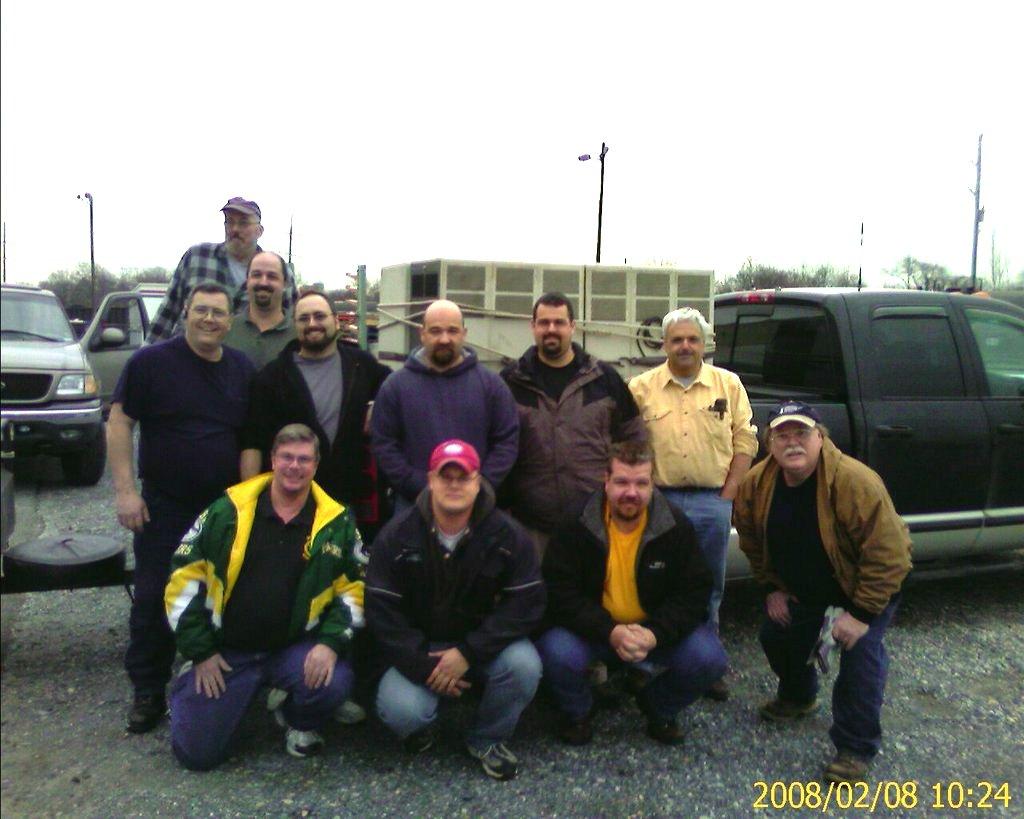
We found the stations all stacked nicely on pallets of four each when we arrived at the company's warehouse in Gibbstown, New Jersey (just outside of Philadelphia). Some were in pristine shape; others were in various conditions, and yet others were marked "FPO" which we assumed meant "For Parts Only". The group consisting of John and Tony grabbed 16 of these lovely units, others took 10 or so, and Jim and I bought three - it was all we could fit into his minivan. (On a side note, I also caused a HUGE gaping injury to Jim's right thumb when it got pinched between the support leg of one of the stations and the inside wall of the van - sorry Jim! Band-aids closed the wound until we could get home, then it was antiseptic and more Band-aids for a couple of weeks.)

This photo show the group of happy hams with some of their bounty - the truck in the background has 12 of the 16 machines destined for Massachusetts, and the trailer holds 4 more!
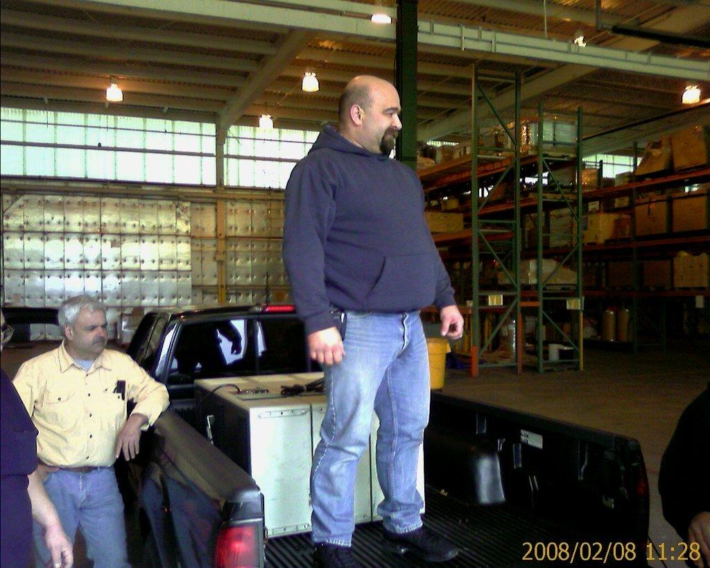
This photo shows one of the two guys mostly responsible for the final negotiations - Tony NN1D standing the back of the truck.
Also, I'd like to note that the warehouse staff at PSEG was more than accommodating to us while we were there - they'd go and retrieve pallets of stations for us, help us open them and inspect them, and they even helped raise them into the back of the pick-up trucks with their forklift truck! What a great experience all around.
Conversion:
So now we have three MSF5000 stations. The first thing we realized - and we knew this even before we picked them up in New Jersey - was that they did NOT contain the High Stability Oscillator necessary for stand-alone operation. These stations were used as part of a state-wide simulcast network by the utility, so they used a single frequency source for the reference and fed that to all stations via an external connection on the side of the cabinet. The other thing we knew was that these stations did not contain a duplexer. So once we got them home, we knew there was going to have to be some work performed in order to convert them from trunked operation to repeater operation.
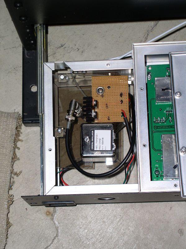
First things first - get an HSO in place so the station will operate. Since Motorola HSOs are few and far between (and cost an arm and a leg), a source of 5 MHz oscillators was located in California. Thanks to Tony and company for that find! I purchased one and when it finally arrived via UPS, set about to get it installed and operating. The HSO required at least a 12V power source, and also had provisions for a 5V source. Since the MSF5000 did not have 12VDC available - most of the power found in the cabinet is either 15.8 or 9.6 VDC - I built my power source from a 7812 and a 7805 regulator. Once I got that done, I removed the external frequency reference input cable from the side of the station cabinet and re-routed it to a piece of Plexiglas that I cut to fit into where the Motorola HSO would mount. I then mounted my voltage regulator breadboard on this same piece of Plexiglas and installed the unit into the HSO drawer of the station.
I applied power to the station, and waited to see if I got VCO lock. After about 45 seconds, the error codes stopped flashing in the control tray window, and the station was ready for operation with its original programming. One thing Jim and I did not run into with two of our stations was a "factory modification" made to most of these stations, where Pin 3 on IC U831 was cut or otherwise removed (sometimes pulled right out of the chip itself) in order to allow for digital-only signals to be processed by the station. From discussion with others who obtained these stations, about 50% appeared to have had this modification performed on them. The problem was, in order for the stations to pass analog signals, this needed to be repaired. Some were able to solder a makeshift jumper across the leg of the IC to re-enable operation; others were forced to replace the chip.
I next re-programmed my station according to a previous article published by Bob WA1MIK, which outlined how to program an MSF5000 for repeater operation. Very nice piece of work, Bob! It made programming my station nearly painless. But I did run into one issue. I wanted to set the ID timer to 9 minutes, and could NOT get the RSS to accept that time interval. After some testing, Bob discovered that the program would only accept even time intervals. (6 minutes, 8 minutes, 10 minutes etc.) Odd, but oh well - we had to live with it. So in order to stay legal with identification time limits, I set the timer to 8 minutes.
Next job was to retune the receiver preselector and VCOs. I did the VCOs first. The Digital Metering Panel (I obtained mine on eBay) was a godsend!! If you don't have one, you might end up chasing your tail to find errors in station programming, tuning, etc. Be sure to get one of these (beg, borrow, or steal it!) if you plan on doing anything with the MSF5000 station. Anyhow, the Receive VCO was close enough to lock, but the Transmit VCO needed some adjustment. Once they were set, the machine was ready for tuning of the preselector.
The alignment procedure is available online - make SURE you get this before starting. DO NOT try to tweak a station by tuning from where it was set when you obtained it - you'll end up chasing your tail trying to get it to tune up properly. My station tuned up on the first try, and showed a receive sensitivity of about 0.10 uV for 12dB SINAD, and 0.22 uV for 20dB quieting. VERY IMPRESSIVE, considering specs are about 0.30 uV for full quieting. A transmit test gave me about 125W at my new frequency pair. I was happy as a clam! On a side note, Bob WA1MIK has written an addendum article about tuning the MSF stations - be sure to get this and read it before you start. It was written after Jim and I (and most of the others) actually got our stations retuned, but after reading it, it certainly makes the job easier. The main point Bob made in the article is to use higher signal levels than called for in the alignment procedure - it makes seeing the dips in the meter readings MUCH easier to note when tuning.
W9JEM's ordeal:
Jim was not so lucky with his station. The first one he worked on appeared to have been repaired, as the Driver Power Amplifier and Final Power Amplifier were both disconnected. One PA also had a tag stuck to it reading, "Repaired - test before placing in use." He tried to reconnect the cabling, but the station would not produce any power on transmit. We never did figure out whether it was a bad PA or if the cabling was not connected properly - and since we had a third station to use for parts, he just swapped his one out for that. This one was all connected up, but had the control tray with the cut Pin 3 leg on U831. I took the control tray out of his first machine and swapped it with the one in the "replacement" machine.
He took that station home, programmed it up, and was able to get good output power when he keyed it up with the switch on the control tray. But he could not get it to transmit as a repeater. I went to his place, and we spent the good part of an afternoon tuning and retuning the preselector, but could never get the machine to key up with an input signal. I stripped the receive preselector and VCO assemble out of the spare station and took it to Jim's, in case we needed to replace his. I also called upon another ham friend, Terry WA9AWO, who worked on these stations for a living to help us out.
After Terry finished tuning the preselector, the station should have worked, but STILL didn't. What WAS the problem?? Since Jim did not have a DMP, I had brought mine. (Jim's panel only had the microammeter, but no digital status indicators.) We all scratched our heads and then connected my DMP to the station. Upon injecting a signal of the proper frequency and PL into the receiver, we could see the receiver status indicate it was "hearing" the signal, and we could see the station calling for PTT, but it just wasn't keying up. Hmmmmmmm... Next thing to check was in programming, and that's where we found the problem. I had not set the station for REPEATER operation. DOH!! Once that was remedied, the station immediately began operating as it was supposed to. This is why the DMP is so important - without the data indicators in Jim's panel, we could not tell the station was actually hearing the signal and calling for PTT.
And now to add a duplexer:
Back to my station... I needed to interface a duplexer, since the site I was going to place this machine at did not have the provisions for split-antenna / multiple antenna operations. So I set about installing a duplexer I obtained (this time via the Repeater-Builder Yahoo! group e-mail list) into the cabinet. I wanted my duplexer fully contained within the cabinet, rather than mounted above or outside the cabinet. So I fabricated some brackets out of aluminum angle, and bolted the duplexer in. Actually, this description greatly minimizes the work done - I had to move the RF Tray / Control Tray assembly lower in the cabinet in order to gain enough space to fit the duplexer in. I also needed to install the duplexer with the tuning rods to the rear, which would make them virtually inaccessible if I ever needed to adjust the duplexer unless I removed the outer cabinet skin altogether. Since duplexers are a "set and forget" item, I did not see where this would be an issue, unless I ever needed to change operating frequencies. And if I ever do have to change frequencies, I'm not going to be doing that at the tower site, so it was a non-issue to me.
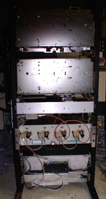
In order to connect in the duplexer, I removed the separate RX and TX connections on the side of the cabinet, and routed them to the duplexer. I had to change connectors to accommodate the input and output connections on the duplexer, and then ordered a cable from RF Connection to go from the output of the duplexer to the side of the cabinet for the external antenna connection to the station. I tried to make my own cable, but apparently my skills are not that good yet, and it did not stand up to the installation - the female bulkhead N-type connector I'd crimped on came right off. Once I installed the new cable from the RF Connection, the station worked like a champ.
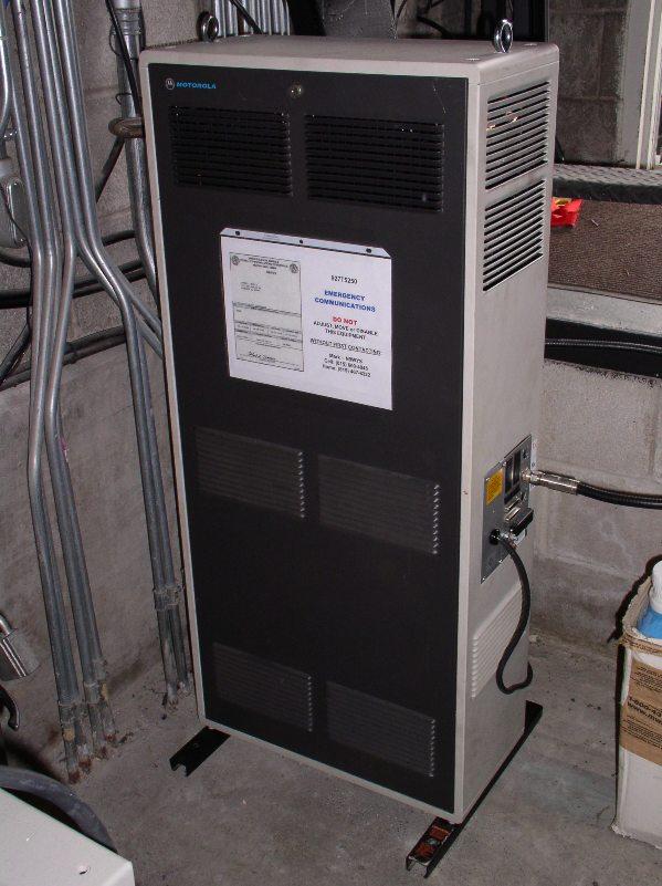
Site installation:
Now to move the station to the tower site. Please know - these stations are HEAVY! You are talking about two power supplies at about 40 pounds each, two power amplifiers at about 30 pounds each, plus the rest of the station equipment, and the weight of the rack/cabinet itself, etc. The location I am at has a short stairwell down to the level where the radio equipment is installed. This stairwell terminates at floor level and there is only about 10 inches of space between the stair bottom and a concrete knee wall. So I installed eye bolts into the top of the cabinet and employed the use of a chain fall to lift the station over the stair railing and then lower it to the floor.
Once placed on the floor, all I had to do was push it into the space it was going to occupy. I set it in place, connected antenna feedline and power to the station and tried it out. All seemed OK, so we took the old homebrew repeater down with us and left the MSF5000 running.
A couple of days later, I was engaged in a long QSO on the machine and after about 10 minutes, I heard the unnerving "beep-beep" of an audible alarm tone from the machine. Checking the resources revealed that this is a "PA Alarm", but the code is not more specific. I do know that it was not an SWR alarm, as these are indicated by a different number of beeps. I was planning on following up, but within a few days, the alarms stopped occurring. Nothing was done to the repeater in between time, so I can only pause and wonder as to what "resolved" the alarm condition. It has appeared again, but only when conditions in the repeater building are hot and humid - over 90°F and humidity above 40%. To date, I have been working a lot and haven't had time to get back up there and test the repeater any more. What is currently done is when the error code sounds, we stop using the repeater for about 5 minutes and let it "cool down". When we resume operations, the error beep is gone, even if we hold another extended QSO...
Odds and ends:
I traveled to Dayton this year - a first for me - and met a WONDERFUL group of hams who all are as interested in 900 MHz as much as I am. Doug even had a portable repeater set up on the flea market grounds that covered the entire site! What fun! Anyway, I found a new-in-the-tube Super Stationmaster for the right price, and bought it. Once I got it home, it went up on-the-air and is happily playing in conjunction with my MSF5000. So now, I think the final assembly is finished, and all I need do now is "tweak it" to work out any bugs (like that error beep) that appear.
And as for Jim's machine - as of this writing, it's also up and running. He was not as concerned with aesthetics as I was - he mounted his duplexer on top of his machine. (Besides, it wouldn't fit within the cabinet, so his options were severely limited.) Site management at his location recently gave him final approval and access to put it on the air.
So if you're ever in or around the Chicago area and are looking to operate on 900 MHz, try our repeaters:
N9WYS: Joliet; Output: 927.5250, PL 151.4; Input: 902.5250, PL 151.4
W9JEM: Lake Zurich); Output: 927.6875, PL 151.4; Input: 902.6875, PL 151.4
Epilogue:
Terry comes to the rescue again! Tonight I was discussing the repeater with him and I described my error beep situation. As it turns out, Terry has experienced this in the past and says it is a fairly well-known fault with the MSF5000 power amplifiers. There is a carbon current-sense resistor that sends a signal to the control tray. This resistor heats up during long key-down operations. (Who does this more than hams? Ever hear the term "lock-to-talk"? hehehe) Anyway, as the resistor heats, the voltage it sends to the control tray changes, and at a certain point, it triggers the "PA Fail" alarm (two beeps).
Terry tells me that this is not a critical failure, and that I need not worry much about replacing the resistor now. It WILL fail, and can be replaced at that time. He also cautioned me to be certain that I replace it with another CARBON resistor of like value - not a wire-wound; not a high-tolerance; not a different voltage rating... I guess I'll just sit back and relax - for now.
73, Mark - N9WYS
P.S. Thanks to Bob WA1MIK for his technical assistance, both with the MSF5000 stations and with the editing and publishing of this article. You are quite the Elmer, Bob!! And also to Terry WA9AWO for his assistance in helping us find where we went wrong with Jim's station, as well as his expertise with troubleshooting the error beeps on my station!
Contact Information:
The author can be contacted at: n9wys [ at ] ameritech [ dot ] net.
Up one level (MSF index)
Up two levels (Moto index)
Back to Home
This article first posted 13-Jul-2008
This web page, this web site, the information presented in and on its pages and in these modifications and conversions is © Copyrighted 1995 and (date of last update) by Kevin Custer W3KKC and multiple originating authors. All Rights Reserved, including that of paper and web publication elsewhere.