Up two levels (Moto index)
Back to Home
by Robert W. Meister WA1MIK

|
Up one level (MSF index) Up two levels (Moto index) Back to Home |
MSF5000 Interfacing for CAT200 / CAT250 Controllers by Robert W. Meister WA1MIK |
|
The CAT200B and CAT250 are repeater controllers manufactured by Computer Automation Technology (CAT). Each supports one repeater and one link transceiver. These controllers have a DB-25F on the board, so they need a DB-25M connector on the end of the cable. The repeater is considered radio #1 and all signals go to that port on the controller. The pin-out on both controllers is identical.
Many other controllers use the same interface signals. This article presents concepts that are not restricted to just the CAT brand of equipment.
This scheme may work with other CAT controllers, but the CAT1000 in particular requires active-low for the COR and CTCSS input signals, so you will need an inverter for one of these. The parts could be soldered to the TTRC board if you're careful.
Power:
The CAT controllers need a clean supply of 12 volts DC at under 100mA. On my UHF repeater, I use the 14-15 volts available on the terminal strip along the bottom edge of the power supply that feeds the power amplifier. This runs into a three-terminal 12-volt regulator (7812-style) that I add to the box holding the CAT controller. This takes the 14-15 volts raw DC, filters and regulates it, and supplies 12 volts to the controller. Some MSF5000 stations have two power supplies; choose the one with higher voltage in transmit. VHF stations use 28 volts for the power amplifiers, so either locate another source of 14 volts, or make sure the regulator you use is rated for 28 volts input. In either case, follow the manufacturer's recommendations: install bypass and filter capacitors at the regulator and mount it to some metal as a heat sink.
Interface Cable:
I interfaced my repeater through the MRTI connector (J802) on the SSCB. I also had to pick up two signals on the TTRC via J2900 and J2901. I used a single-row, 20-position, non-polarized connector housing (Jameco 103182) cut down to 14 positions, and the mating female pins (Jameco 100766). These female pins fit the MRTI connector as well as the TTRC connectors. (Note that Jameco occasionally changes part numbers or replaces them, so search for the description if the part numbers can't be found. The numbers above were valid in January 2011.)
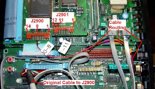
The DB-25M connector is labeled "CAT250". The MRTI connector is labeled "MRTI" and has pin 1 marked with "1". The wires going to the TTRC are labeled "J2900-8" and "J2901-11".
I used a few feet of 8-conductor 22-gauge stranded Alpha cable in a gray PVC jacket that I had on hand. The cable is wired as follows:
| Pin | CAT Signal | Connection (active level) | Color |
|---|---|---|---|
| 4 | CTCSS In 1 | TTRC J2900 pin 8 (LOW) | RED |
| 6 | COR In 1 | TTRC J2901 pin 11 (HIGH) | BROWN |
| 10 | PTT Out 1 | MRTI J802 pin 5 (LOW) | GREEN |
| 11 | TX Audio Out 1 | MRTI J802 pin 8 | WHITE |
| 13 | RX Audio In 1 | MRTI J802 pin 10 | BLACK |
| 14 | Switch Out 1 | MRTI J802 pin 4 (LOW) | YELLOW |
| 17 | Ground | MRTI J802 pin 1 | BLUE |
| 18 | Ground | MRTI J802 pin 13 | ORANGE |
Installation:
1. Remove power to the station.
2. Remove any retaining screws in the front panel of the RF tray.
3. Slide the RF tray out.
4. Swing the control tray to its service position.
5. Unplug the flat ribbon cable going to J801 on the SSCB, by flipping the two handles outward and pulling the plug out of the connector.
6. Fold the flat ribbon cable out of the way, onto the top of the RF tray.
7. Move all the other cables coming up to the control tray towards the back of the station to make space for the new interface cable.
8. On the right side of the RF tray, route the loose end of the interface cable from the inside of the station along the same path (above the slide) that the other cables are running. You may not have enough room to push the DB-25 connector through if you don't do this now.
9. Bend the wires so the MRTI connector is vertically oriented and push it up along the front edge of the channel in side of the RF tray where all the other cables go.
10. Pull the MRTI connector and the pair of wires up through the hole in the casting.
11. Plug the MRTI connector into J802. Pin 1 is towards the front of the station (see photo below).
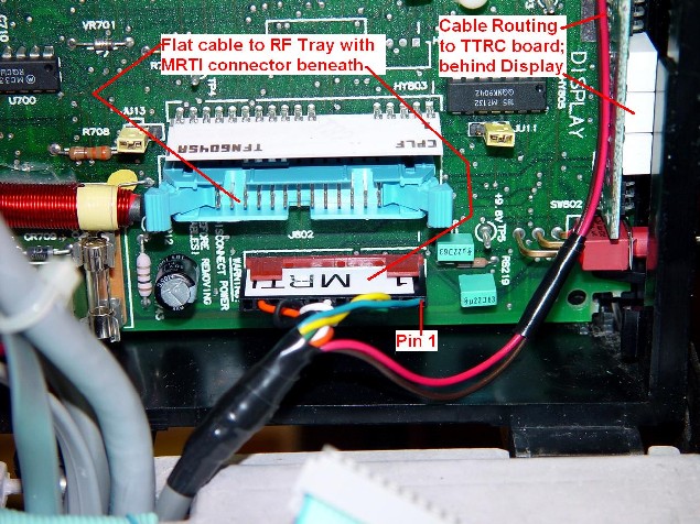
12. Route the pair of wires toward the front of the SSCB, along the rear of the display board, and up to the top of the SSCB (see photos above and below).
13. Remove any cables plugged into the TTRC J2900 and J2901. Put them where they won't interfere with the TTRC.
14. Plug the bare connector on the brown wire into J2901 pin 11 (see photo below).
15. Plug the bare connector on the red wire into J2900 pin 8 (see photo below).
16. Fold the wires up near the MRTI connector.
17. Pull any slack in the interface cable back out of the control tray.
18. Replace the flat ribbon cable going to J801 and secure the latches.
19. Close the control tray to its operating position.
20. Use a couple of nylon cable ties to hold the interface cable along the same path as the existing cables along the right side of the RF tray. If you remove the outer cabinet skin it's a lot easier to see and tie the new cable. Note that I have not tied my cable as it was not remaining in this station (see photo below).
21. Slide the RF tray back into the station and secure it.
Controller Configuration:
I have installed 10k resistors for both R36 and R37, the two COR input pull-up resistors, on the CAT200B circuit board. There are similar pull-up resistors in the CAT250. CAT says they supplied 2.2k resistors but I thought that was too small. You only need one for COR #1 but I put both in when I first got the unit.
The controller has a DIP switch (SW1) that sets the signal polarity. Set the following positions:
1 - OFF (COR active high)
2 - ON (CTCSS active low)
Certain zone settings also need to be made:
Zone 1, channel 1 - ON to enable the repeater
Zone 1, channel 2 - ON to enable CTCSS access
Zone 1, channel 3 - OFF to allow COR "AND" CTCSS mode
Note that the wording in the CAT250 manual about Zone 1 is somewhat misleading. It seems to be better written in the CAT200B manual, shown below:
Zone 1, channel 2: Repeater CTCSS Enable
When this channel is enabled, in addition to a COR input, an input from a CTCSS decoder
at J3-4 must also be present before the repeater will activate. A COR input by itself
will have no affect. To prevent loss of control, DO NOT ENABLE THIS CHANNEL unless a
CTCSS decoder is connected to J3-4.
Zone 1, channel 3: Repeater CTCSS OR Logic Enable
When this channel is enabled, the COR and CTCSS inputs will function as a (OR) logic
input. This means activity on either the COR or CTCSS inputs will cause the controller
to key the repeater's transmitter. This is a layered command. Therefore, Repeater CTCSS
Enable, Zone 1 Channel 2, must be ON or this control function will have no effect.
USER Output Switch #1 (CAT250: Zone 5 Channel 1, CAT200: Zone 3 Channel 5) is used to enable or disable PL/DPL in the MSF5000. It does this by grounding the MONITOR line to put the receiver in carrier squelch. Setting this channel ON sets the switched output low and enables carrier squelch. Under normal circumstances (PL/DPL required), this channel should be left OFF.
MSF5000 Configuration:
You may want to read the companion MSF RSS Programming article to become familiar with the location of these fields. It goes into a lot more detail than this article does.
The MSF5000 needs to be set up as a base station, NOT a repeater. However, the field "REPEATER" needs to be set to "ENABLED" so the receiver stays active when the transmitter is on.
You need to set MRTI ENABLED on page 6 of the Advanced Settings menus.
In the PTT PRIORITY list, make sure MRTI (M) is present. It makes sense to put the local microphone (L) first in the list. If you want to use the wire-line interface, add that too (W). Do NOT put the repeater (R) in the list. I use LWM so everything else is higher priority than the external controller.
Set the LINE and LOCAL time out timers to 180 seconds. Set the MRTI time out timer to 000 seconds, as the external controller will handle this.
Set the Repeater and RX Audio Control to "SC" for carrier AND coded squelch.
Usually one mode and/or channel is sufficient. Delete the others. This way, the station can only power up in the desired mode.
You don't need a CW ID or any of the repeater-oriented settings.
Set the "idle" frequency to something about 50 kHz away from the transmit frequency so you don't "hear" the VCO when the repeater is not on the air. Make sure this frequency does not interfere with any existing services at the site.
Set both the Receiver Squelch and the Repeater Squelch using a diagnostic metering panel. Adjust both so the appropriate LED just goes off, then increase each about 5 digits. You can also see these signals if you have a computer attached to the station; one of the service screens displays the MUXBus signals and another can be used to adjust the EEPots.
Acknowledgements and Credits:
Most of the work had already been done by me several years ago when I attached a CAT200B controller to my MSF5000 UHF base station and turned it into a repeater. I wrote an article describing many of the signals; it's already out on the web.
Connection and configuration information for the CAT200B and CAT250 controllers was obtained from their official User Manuals, available from the CAT Automation factory web site.
Interfacing information for the MSF5000 was obtained from various Motorola service manuals.
Contact:
The author can be contacted at: his-callsign [ at ] comcast [ dot ] net.
Up one level (MSF index)
Up two levels (Moto index)
Back to Home
This article first posted June 2006.
Article text and photos Copyright © June 2006 by Robert W. Meister WA1MIK.
This web page, this web site, the information presented in and on its pages and in these modifications and conversions is © Copyrighted 1995 and (date of last update) by Kevin Custer W3KKC and multiple originating authors. All Rights Reserved, including that of paper and web publication elsewhere.