According to the Motorola sales brochures from the era, the "MSF" stands for "Maximum
System Flexibility". The MSF5000 project name was "Calypso". The MSF10000 is the
European version (no encryption support), and the PURC5000 is a paging base station that
was derived from the MSF5000 (the older plain "PURC" station was MICOR-based).
"PURC" was a marketing-department-generated abbreviation and stood for Paging Universal
Remote Control, which was a paging-oriented modification to the standard tone remote control
format for transmitter keying in both the analog and binary mode. Some MICOR-based PURCs
and MSF-based PURC5000s had cross-band receivers (usually 75 MHz or 900 MHz),
others were analog wire-line controlled, others had modems that passed digital data from a
leased digital wire-line to the transmitter.
An interesting thread providing some PURC5000 station
info can be found here.
From the amateur radio point of view the MSF paging station can be used as a good foundation
for a continuous duty amateur radio repeater, you just need to add a decent recevier. There are
two Micor-based receiver chassis, either the "Auxiliary Receiver" or "Link Receiver" would be
a great start. If you want a synthesized receiver the Maxtrac or GM300 prefaced with a single
pass cavity as a preselector would work.
The MSF5000 stations come in two basic types: the early ones with "CLB" or
"JLB" in the model number, and the later ones with "CXB",
"GFB", "RUB", or "RLB" in the model number.
Note that ALL of the MSF models have their operating program(s) in one or more
UV Erasable firmware PROM(s).
From the amateur radio point of view all of them are the same, except for how you
program them. And you will probably only find a CLB or a CXB.
The "CLB" series (the first generation) are commonly called the
"analog" stations and hold their parameters (RF frequency, PL tone or
DPL code, etc.) in a 2732 family UV Erasable EPROM and the operating program
(firmware) in a 2764 family EPROM. Setting one up a CLB requires access to a R-1800 or
R1801 suitcase programmer equipped with the MSF program PROMs and the programming
module for the 2732 chip. If you have a "CLB" and don't have a suitcase programmer
you will need to find someone who does or spend a lot of money to buy one yourself.
You will only need it once to burn the frequency and configuration profile PROM for your
station (unless you need to change the RF frequency or the tone). And just having the suitcase
isn't everything; the unit has to be configured for the MSF – it has to have the MSF
firmware and correct EPROM-burning adapter. See
this web page on what it takes to program a "CLB" series MSF (it's an
offsite link and will open in a new browser tab).
Yes, Andy can program a 2732 chip for you.
See the MSF beginners Guide page for some info
on the 2732 (look for the paragraph that starts with "The 2732 can be a difficult chip
to use".
The second generation MSFs were the "CXB", and the derivations
("GFB", "RUB", and "RLB" models) are all PC‑programmable.
The "CXB" are commonly called the "digital" stations.
This is a total misnomer as they aren't "digital" stations but "digital‑capable".
These could be used with Motorola's SECURENET encryption packages.
"Digital capable" simply meant that the station could be equipped for
SECURENET encrypted communications - a 12 kbps (two level) digital SecureNet
modulation format (DES or DVP). Note that the MSFs were designed and manufactured
many years before P25 was even thought of, and the digital modulation format is
definitely NOT any form of P25.
The MSF secure option board enables the station to perform as a true digital
repeater by regenerating the recovered inbound data. It can also encrypt and
decrypt analog audio from and to the station's analog wire-line (the leased circuit
from the station to the dispatch console), enable repeat based on proper code detect, etc.
Units with "GFB" in their model number are commonly called
"Analog-Plus"; they're essentially a "CXB"with the secure
communications capability deleted and therefore could be exported. The "RUB"
was a Canadian "CXB", and the "RLB" was an option-limited
"CXB" (limited by marketing, the hardware was pretty much the same).
A "JLB" is a transmit-only (i.e. paging) version of a "CLB"
(which used the marketing name of "PURC5000"), a "JXB" is the
similar version of a "CXB", and a "JFB" is the similar version
of the "GFB". A paging station might have a receiver in a different band,
or a MICOR receiver in an auxiliary chassis, or no receiver at all... some had a wireline
modem in place of the receiver.
In summary: The "CLB" and the "JLB" are EPROM
based and changing frequency or tone required swapping a PROM chip, all other MSF5000s
are PC programmable. A J-something is a paging station and needs to be carefully examined
to see if it has a usable receiver (probably not) and if the station is usable may need to have
the firmware chip (a 2764 family) replaced with one from a regular CLB station.
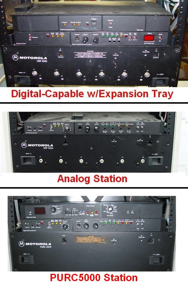
The front panel control shelf on the MSF identifies the type of controller it
has. First find the volume and squelch controls; they will be on a small sub-panel
of the control unit. If you see a three-digit red LED display window at the right side
of that sub-panel, then it's a "CXB", "RLB", or "GFB"
that is programmed by a PC via a serial cable. If the red LED display is on the top
left then it is a PURC5000. If there is no display at all then it's one of the
"CLB" series that needs the suitcase programmer. A front panel photo of all
three is at the top of this page, more photos of the "CLB" and
"CXB" series are on the "Photo Tour" article.
All of the second generation (CXB) stations are programmed via a serial port, which
can be accessed via the front panel microphone jack or by way of the control or expansion
jacks of the control tray. You will need a PC with a real hardware serial port booted
into MS-DOS and running Radio Service Software (RSS) product number RVN4077G (the
final version was R05.21.00), a RIB and the correct cable to connect to the MSF.
The RSS must run under MSDOS, it will not run properly in a DOS box or under
any version of Windows.
I repeat: The programming computer MUST have a real hardware serial port.
There is an "RSS and RIB" web page on this web site that covers some
of the details on them, and some of the limitations of the RSS software.
An interesting and informative thread on 800 MHz
versus 900 MHz MSF stations and how to tell them apart by the model number can
be read here.
The short version: any Cn5xxx-n1nn (where x is a letter and n is a number) is 800 MHz
and Cn5xxx-n2nn is 900 MHz. The conversion of an 800 MHz MSF to
900 MHz is VERY difficult, there are much easier ways to build a
900 MHz repeater.
All MSF5000 stations have an independent receiver and transmitter and can receive
and transmit at the same time, in other words they can operate full duplex. If an
internal or external duplexer is employed, then the station can act as a repeater
and utilize just one antenna. Alternatively, two separate antennas can be used.
In either case, reception of the correct incoming signal will cause the
transmitter to be energized. The station can also be programmed as a base station,
which implies some sort of wire line remote control, because the received signal
will NOT key the transmitter. An antenna relay is used to switch the single antenna
to either the receiver or the transmitter, or two separate antennas could also be used.
The main point is that the station can be configured - with the appropriate hardware - to
run as either a base station or repeater station, and it's usually easy to convert between
the two. PURC5000 stations are merely the transmit half of the full MSF5000 station;
all of the internal receiver circuitry is on another band (frequently 75 MHz)
or missing.
EBay buyers: beware!
Two major points:
1) These units are VERY HEAVY (150 to 300 punds (70-140 kilos), depending on the
features and RF power level). The shipping will probably cost more than the unit.
2) No matter WHAT the model tag says, no PURC, MSF or PURC5000 station will
ever operate over the entire 132-174 MHz or 403-475 MHz frequency
band listed on its model tag / label!
Each station will do only a portion of that model tag frequency spread, called a
"split", a "band-split" or a "range".
Unfortunately, there are only two ways to determine the band-split of your station.
You either have to read the code plug (with RSS or the suitcase programmer) and look
at the information it displays, or you have to find a part number tag or a part number
rubber-stamped on a major frequency-sensitive assembly (PA, RF Tray, VCO).
Look for a part number in the format of xxxnnnnx where x is a letter and n is a number.
The last digit is the critical digit.
| Band |
Range |
Frequency |
| 3 (VHF) |
1 |
132-158 MHz |
| 2 |
146-174 MHz |
| 4 (UHF) |
1 |
403-435 MHz |
| 2 |
435-475 MHz |
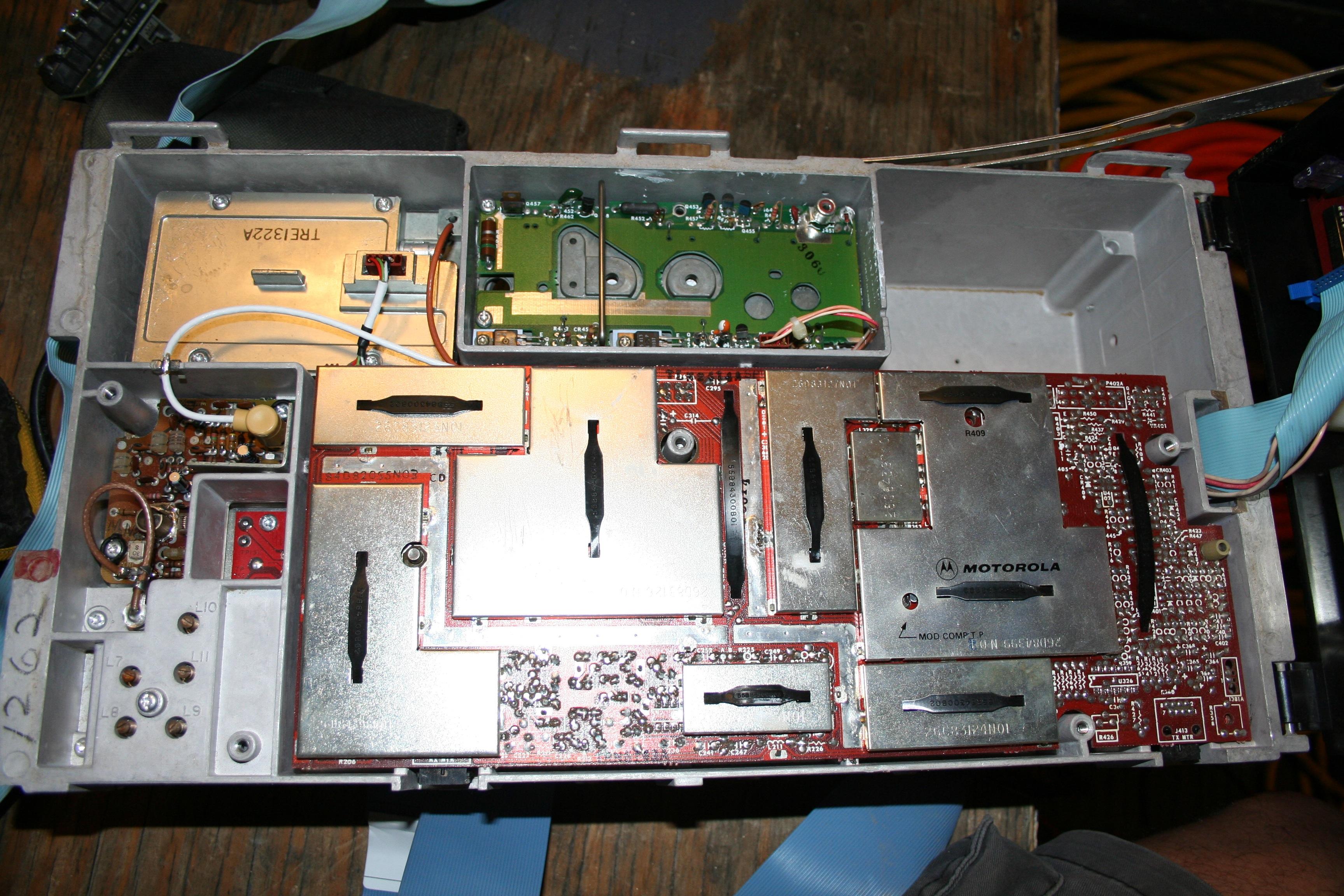
Please take a look at
this photo of the RF drawer
of a UHF station. Look at the top left and the top right of the photo... the
yellow labels (which have also been seen with an orange background) on the VCOs
read TRE1322B and TTE1472B. The "R" is the receiver, the "T"
is the transmitter, the "E" indicates UHF (a "D" would indicate VHF)
and the the last digit is a "2" which indicates it is a range 2 station.
Now look at the bottom left.
The label on the lower left lip of the drawer reads TUE1972A - that's the part number
for the entire UHF range 2 drawer.
Note: the trailing digit indicating the range is frequently a good range indicator,
but it is NOT 100% across Motorola... on the MSF product line it is. My personal
rule is that before you spend your money you need to check the manual, or if you
can (and if it is a CXB), read the station with the RSS.
The first generation MSF ("CLB" and "JLB" EPROM-based)
stations have a CW identifier whose timing (15 minutes) and tone frequency is controlled by
a byte (or bytes) in the code plug EPROM. The MSF programming software that runs
in the 1800/1801 suitcase programmer does not have the ability to program those bytes
with user-specified values (that was an oversight). As a result almost every analog
station I've seen in amateur service has been programmed as a duplex base station
(with the IDer disabled) and fitted with an external controller that does the ID and
a lot more.
Update: There is now a ham-written program that can edit those bytes (and a LOT
more) in the EPROM image file and allow changing those values. The first generation MSF
can now be a legal amateur repeater while using the internal controls.
There is a known bug in the MSF digital station (CXB) firmware. Unfortunately
it's never going to be fixed by Motorola as the MSF line has been off the support list
for over 20 years. Maybe a ham will reverse engineer it and let us post the fix...
The Auto ID Interval field will accept any value, but seems to reduce it to the next
lowest 5, 10, 20, or 40 minute interval. You can enter 009 but it seems to change that
to 000 (disabling the ID). All other values between 001 and 010 work fine. 11-14 get
reduced to 10. 15 works fine, but exceeds the FCC rules for amateur repeaters
(10 minutes). This bug isn't a problem with systems that are configured with
external controllers as they don't use the internal CW ID.
Speaking of CW ID, the deviation level of the internally-generated tones
(CW ID and alarm) in a stock MSF is a fixed percentage of the total deviation and
not adjustable. Many people complain that it is too loud. There are several
ways to deal with this issue:
- Make sure the station deviation is set correctly to 4.5 to 5.0 kHz maximum (2.0
to 2.5 kHz for 800 MHz / 900 MHz stations). Set it
with PL / DPL activated.
- Adjust the various timing parameters such that the CW ID is sent when the
transmitter is otherwise off; the CW ID will be sent without PL / DPL,
and a coded receiver won't hear it. If users can't hear it, they won't complain that it's
too loud.
- Adjust the CW ID parameters in RSS for tone and speed. Higher frequency
audio tones will sound softer on a de-emphasized receiver, since the IDer tone isn't
pre-emphasized in the transmitter.
- Change a resistor value or two on the SSCB (requires removing the SSCB board
from the drawer) to change the CW ID deviation percentage (lower the ratio), or even
install a potentiometer in place of the two fixed resistors. Once you have the ratio you
want, then readjust EEPot #4 to get the total deviation back where it belongs.
- Disable the internal IDer and use an external repeater controller that gives you
the ability to adjust the CW ID tone level separately. See the "Interfacing" articles in
the MSF section.
- Live with it and enjoy all the other good things the MSF is known for.
Once you start tuning up the MSF you will discover an annoying "gotcha":
the MSF station does not have a speaker on the receiver; in fact it has a low level
(1/2 watt) amplifier that was designed to drive the earpiece in the test handset and
not much more. Due to this situation both models of the MSF5000 test set contain
an amplified speaker.
The TMN6164A test handset is extremely rare - I have
seen exactly two in over 8 years on eBay. If you want to build your own it would not
be hard to take any Western Electric or ITT "G" series telephone handset, put a PTT
button on it somewhere, add a 560 or 620 ohm resistor in series with the earpiece,
and if you can't find a 6-wire curly cord to crimp a 6-wire RJ-11 plug to just add a 6-wire
RJ11-style cord to it (and yes, I know that a "real" RJ-11 has only 1 pair (two
pins), a RJ14 has 2 pairs (4 pins) and a RJ-25 has all three pairs (6 pins), but nobody
uses the RJ14 or RJ25 terminology. Everything in a 6-pin body is referred to as an RJ-11).
The HMN1001B microphone plugs right into the 6-wire RJ jack in the station control
tray and allows you to locally key the transmitter and talk over it. There is just one
problem: the HMN1001B is rather rare, and when found is usually expensive as everybody
with an MSF or a Quantar wants one. A cheap
equivalent is to take a common 8-pin (i.e. RJ45 style plug) microphone from a Maxtrac,
Radius or GM300, an RJ45 jack with screw terminals (as opposed to punchdown style
terminals) and a short 6-pin RJ11 silver-satin cord and mate them. Just take the pinout
of the RJ45 microphone (available on the Maxtrac / Radius/GM300 page at
this web site), the schematic of the TMN6164A test handset
data sheet (which includes the pin-out of the connector) and make yourself a microphone
adapter cable (and yes, I know that an 8-wire analog RJ connector is an RJ-61 jack, but
everybody refers to it as an RJ-45). This gives you an inexpensive test microphone.
If anyone has the part number for the replacement cord for the HMN1001B microphone
please let me know so I can add it here. One could be ordered and installed in any common
Motrac / Motran / Mocom / MICOR etc.
microphone and that would give one a cheap MSF or Quantar test mike.
Personally, I prefer having a common mobile microphone and a local speaker that has
enough volume to be useful. As long as you are making up a microphone adapter, why not
do the following: take a common mobile speaker, build up a common LM386 ampifier circuit
on a piece of perfboard (see this page). Then mount
the perfboard inside a mobile speaker case, with the volume control pot mounted in the
outer case (or even in the center of the grille). The use of a pot with a switch allows
turning the amplifier off when you aren't there. Then cable the amplified speaker into the
RJ45 microphone adapter box: connect the audio input to pins 2 and 5 of the headset jack,
mount the mobile speaker somewhere in the repeater cabinet, and pick up +12vDC for the
amplifier from any of several places in the drawer. This gives you a proper local service
speaker and a test microphone. Just remember to program the local mike as having the
highest priority.
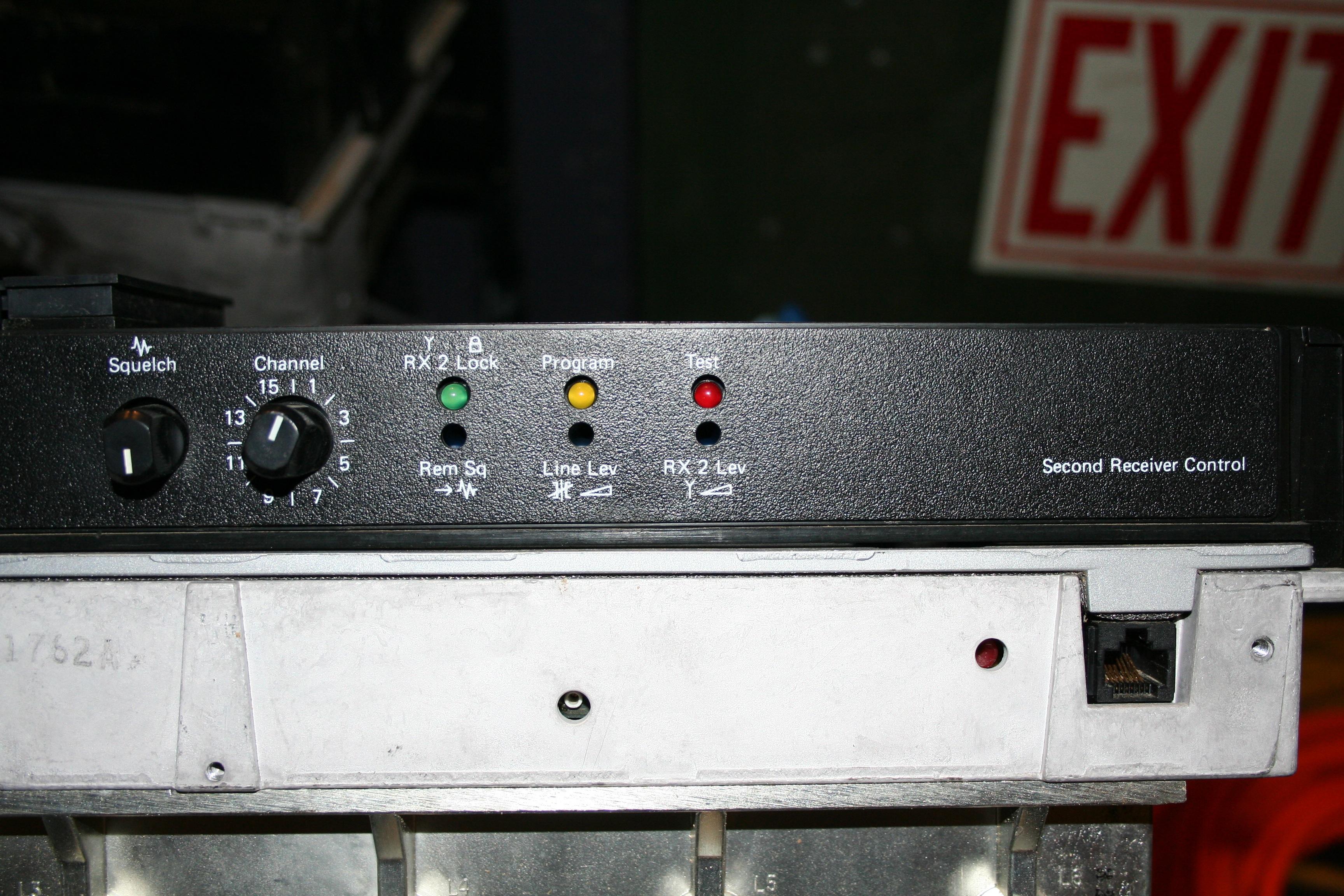
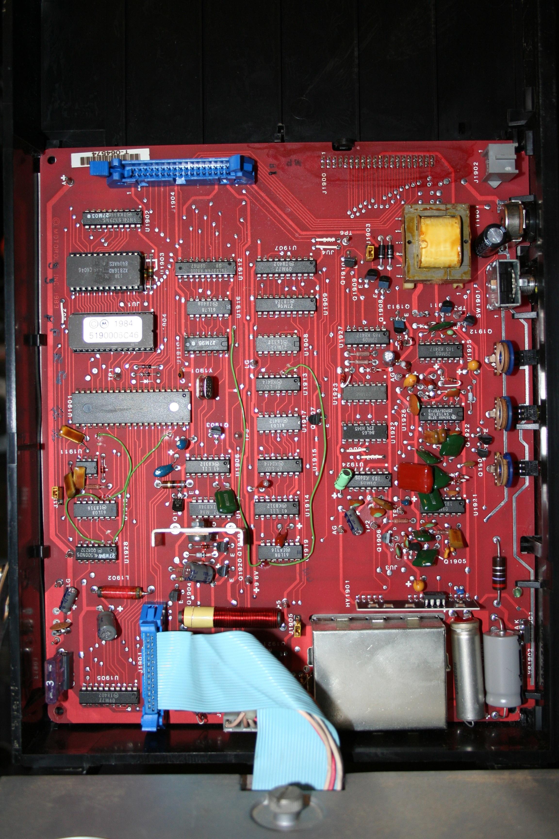
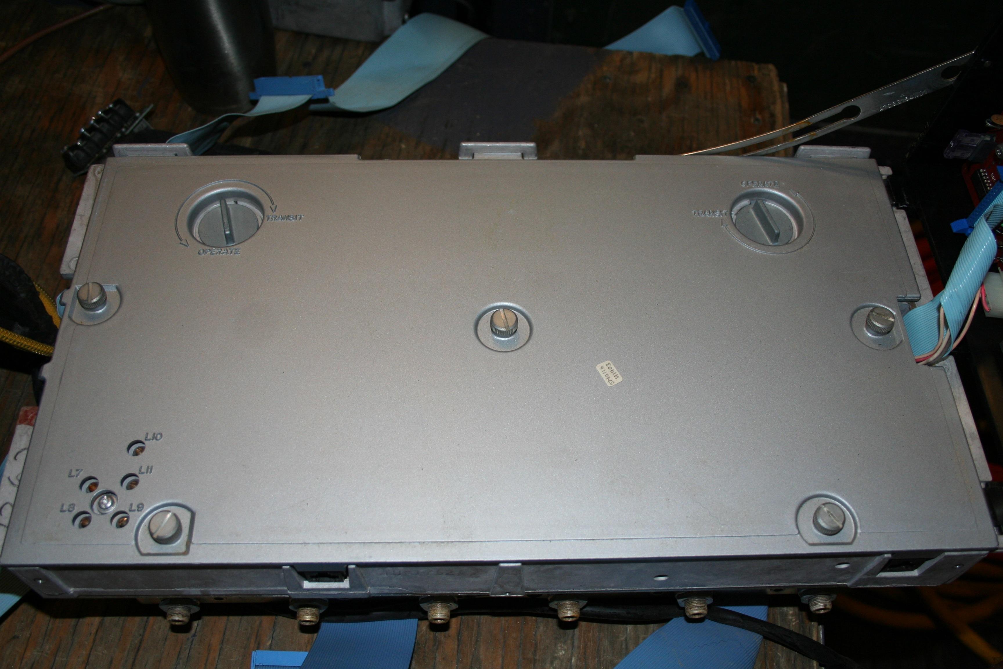
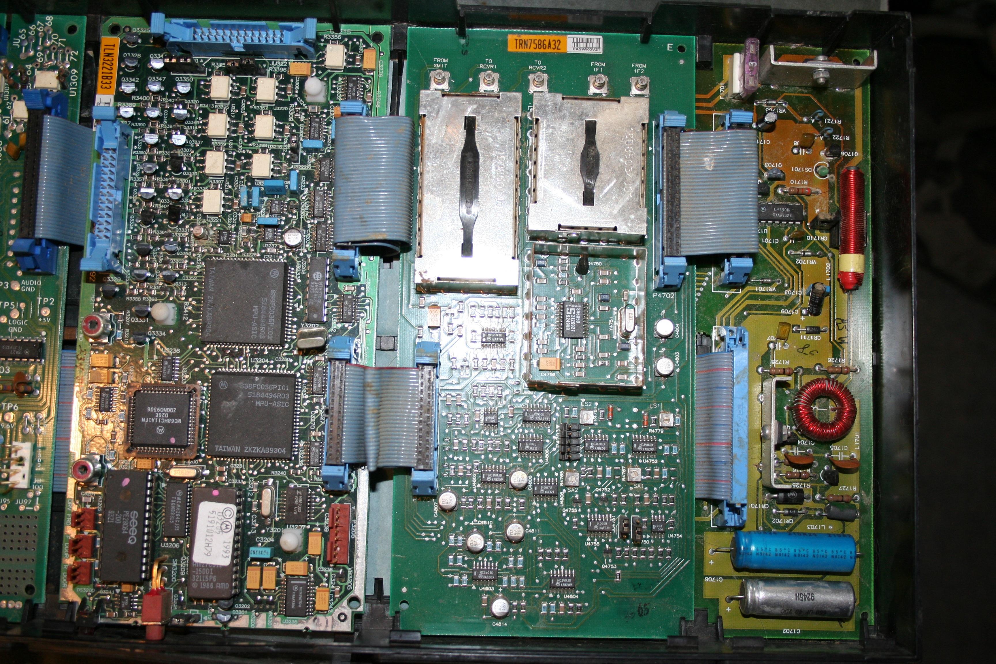
MSF5000s were sometimes equipped with a second receiver and control tray.
Here's a photo of the control panel of the second
receiver's control tray. Here's a photo
of the control board that's inside that control tray. Here's a photo of the top cover of the RF Tray.
Here's a photo of the inside of the RF Tray.
Note that the front panel resembles what you'd find on an older analog (CLB)
station. Also the RF Tray is missing the IPA (Intermediate Power Amplifier) and
the transmit VCO, because these aren't needed in a receive-only chassis.
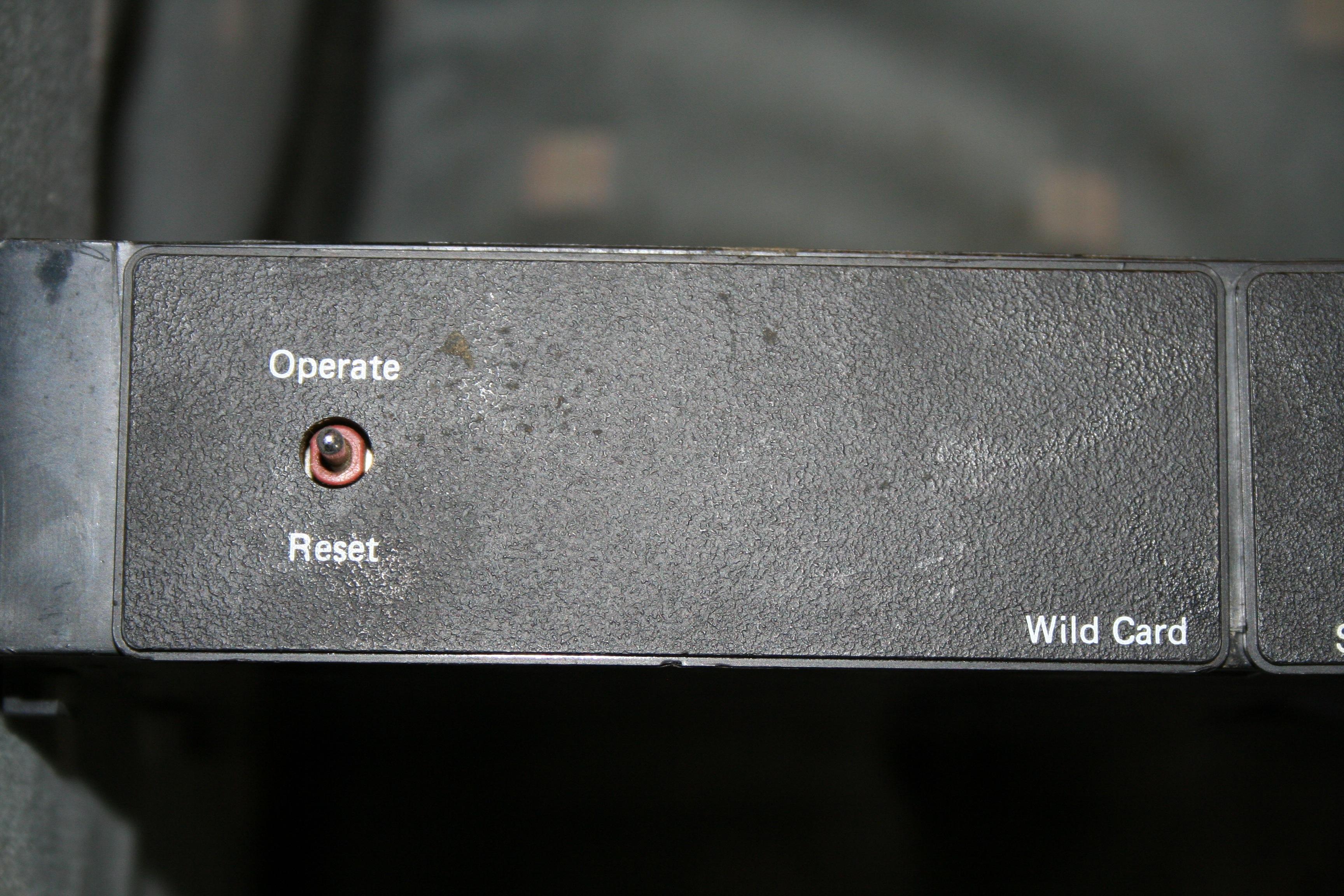
Expansion trays usually were equipped with a Wildcard module. This board has
four digital inputs, four digital outputs, and up to four relays, that can be wired
up to do all sorts of unique things, providing special features that customers
ordered. Every unit was different and exact schematics are almost never available.
The wildcard module usually looked at, and modified, the data on the MUXBus,
which is displayed with the Digital Metering Panel (that's the one with 64 LEDs
on it).
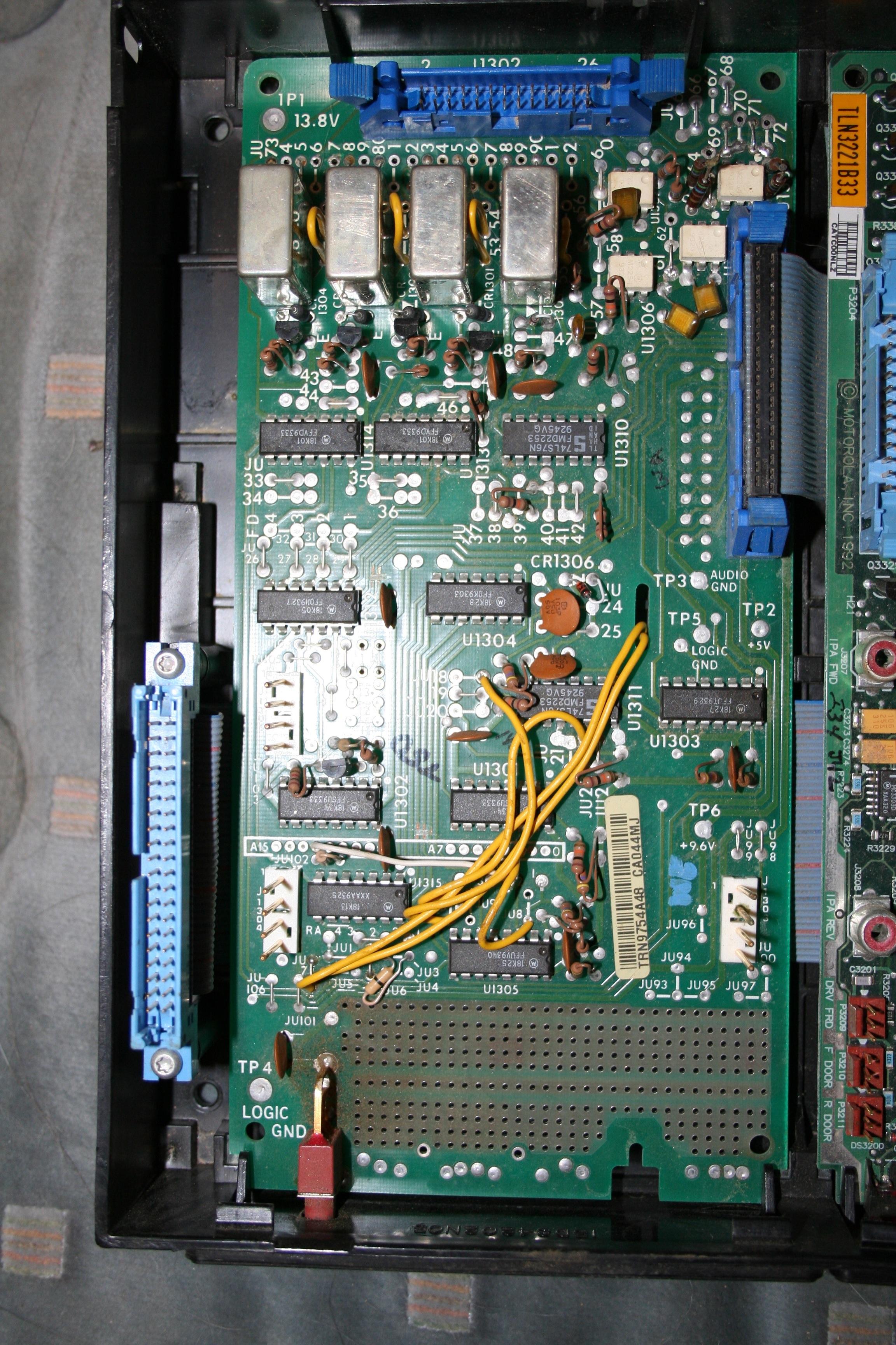
Here's a photo of the wildcard control panel
in an expansion tray. Here's a photo
of a wildcard circuit board in an expansion tray. Here's another wildcard and power supply circuit
board pair in an expansion tray. The module at the right is a power supply
regulator for all the other modules in the tray. This last photo is by WA1MIK.
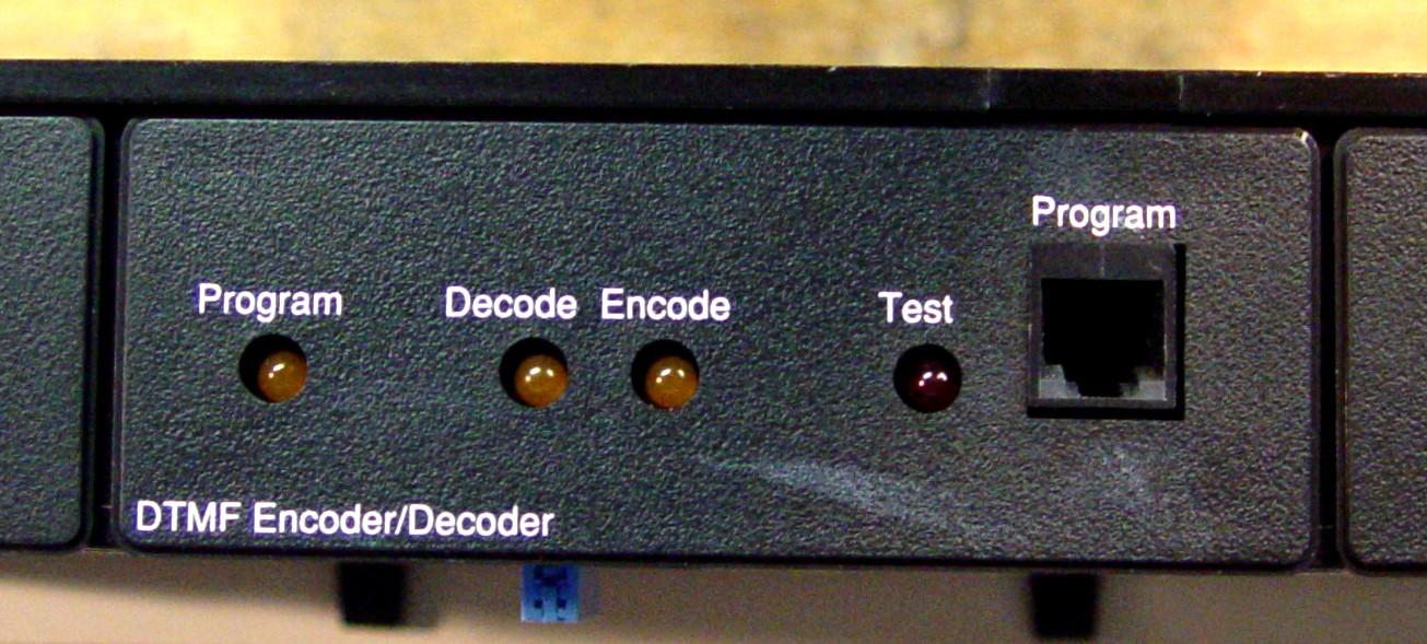
Another popular option was the DTMF Encoder / Decoder, which was
programmed via RSS. These modules tended to be found in analog (CLB) stations, as the
DTMF functionality was moved to the SAM for the digital-capable stations. This module
also has limited speech output capability. Here's a photo of
the DTMF control panel in an expansion tray. Here's
a photo of the DTMF circuit board in an expansion tray. Both photos are by WA1MIK.
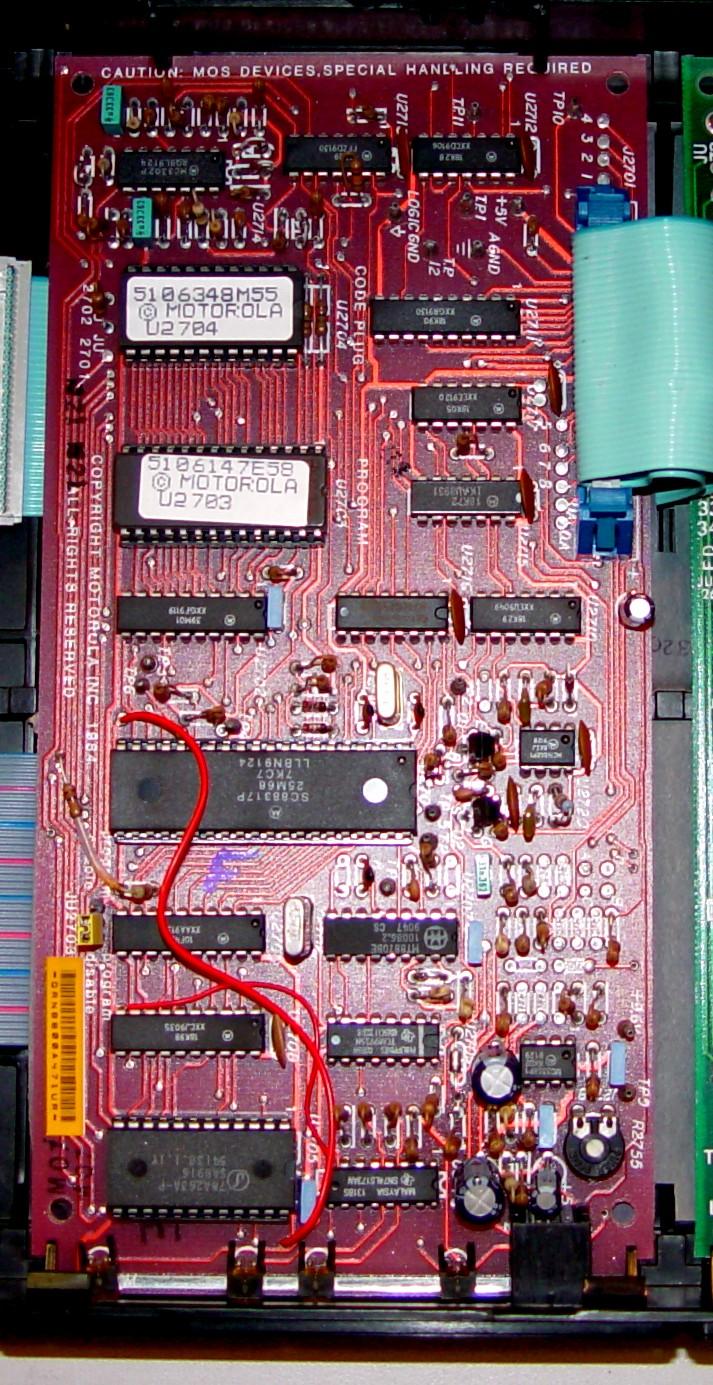
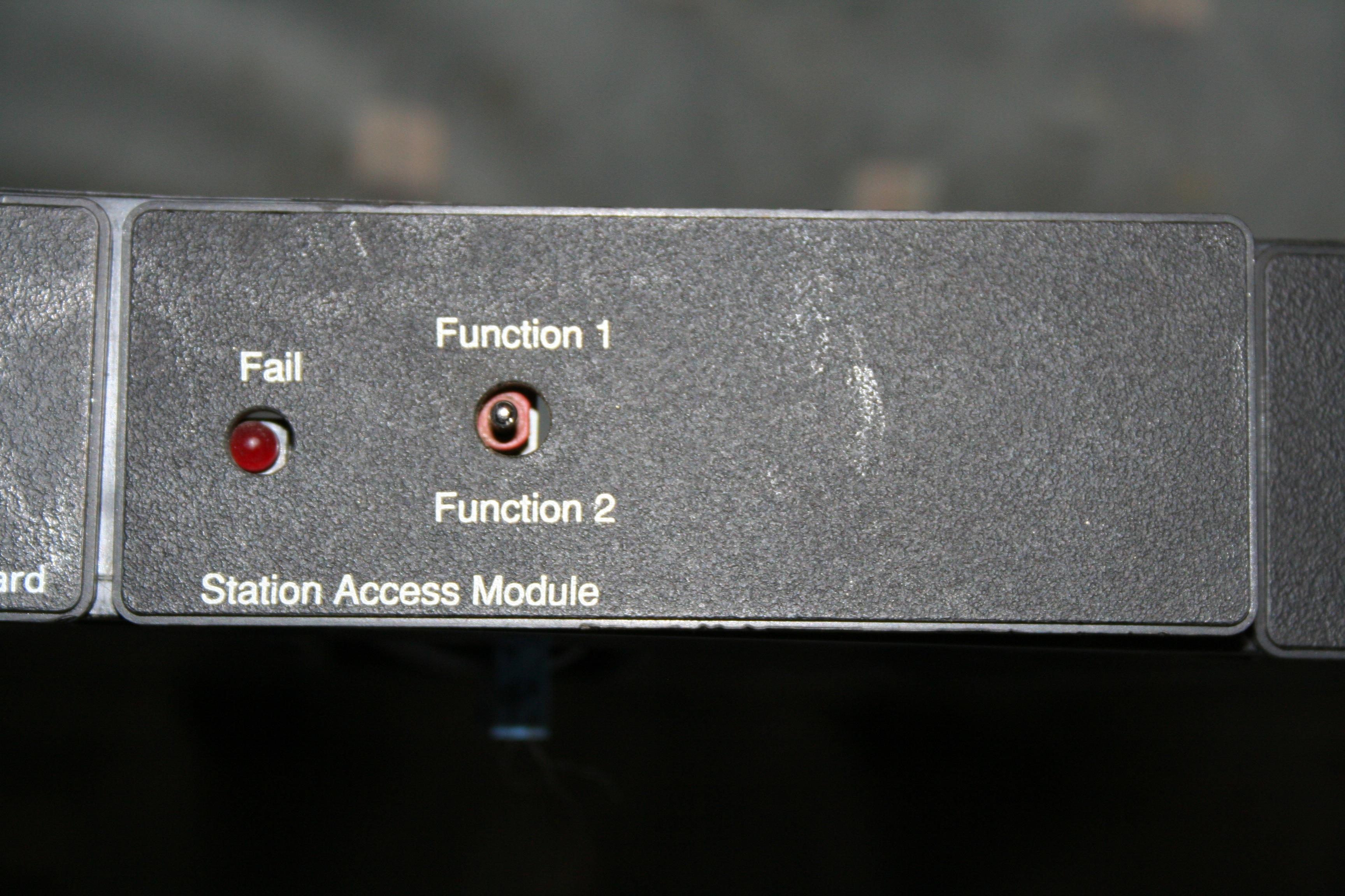
Another option that was a bit more rare was the Station Access Module (SAM). This
board was meant to replace the wildcard module, letting you do everything via
software (programming through RSS). There are more inputs and outputs, a built-in
DTMF encoder and decoder, and several software digital data decoders (such as MDC1200).
In addition, it could perform limited diagnostics on the station and report many more
error conditions.
Here's a photo of the SAM control panel in an expansion
tray. Here's a photo of the SAM circuit boards in
an expansion tray. The right-hand board is for diversity reception operation.
Both of these are documented in the "MSF5000/10000 Data Station Smart Wildcard and
Diagnostic Options" manual.
Common terms and answers to Frequently Asked Questions:
- SSCB: Secure-capable Station Control Board. It's the main brains of the MSF5000
station and is the larger of the two boards in the plastic control tray. This board
MUST be present for the station to work. On analog (CLB) stations, this board is called
the SCM: Station Control Module.
- TTRC: Trunked Tone Remote Control. Provides 2 and 4-wire wire-line interface with
both DC and high-level guard tone signaling, standard for this sort of interface. It
also provides additional input/output capabilities. This board is optional and not
needed for some configurations. On analog (CLB) stations, this board is called the TRC:
Tone Remote Control module. The TRC board could be replaced by a DC Control module or
a Trunked Control module.
- SEC: Secure board. Not used in the amateur radio service. It provides transparent
and encryption/decryption security for digital communications. It can only be installed
on a system with an SSCB (i.e. an Analog-Plus or Digital-Capable station).
- The only option that fits in the control tray is the Secure board. An expansion
chassis was used for everything else, such as Multi-Coded Squelch (MCS), DTMF, or a
WildCard board. All of these can be removed but you must disable them in the code plug
and possibly change a jumper on the SSCB before phyically disconnecting them. There are
articles on this web site that tell you how to do this. If you don't, you'll have to
create and write a new code plug to the station with the correct options enabled.
- RSS version R05.21 is the latest. The software is No Longer Available from Motorola
but it is floating around "out there" on the web.
- SSCB codeplug firmware version: the latest I've seen is 5.52.
- TTRC codeplug firmware version: the latest I've seen is 5.41.
- The firmware EPROMs are not copy-protected. You can make a copy of an EPROM
and install it, but the layout of the code plug changes with System Versions. There are
only so many legal combinations of firmware versions. Note that RSS incorrectly
identifies versions, but if it says "upgrading codeplug version" that usually means
it's going from one System Version to a higher System Version. There are only three
System Versions; there's a table of them in the MSF5000 RSS Programming article on
this web site.
- When you swap EPROMs and the System Version changes, the layout of the code plug
data also changes, hence the "upgrading codeplug version" message above. The correct
way to replace firmware is to read the code plug from the station and save it to disk,
unplug the station, replace the firmware EPROMs, power the station up, then write the
code plug back to the station, letting RSS figure out what System Version is it. After
it's been loaded, it's wise to read it back and save it as another file. Make sure the
firmware versions correspond to a legitimate System Version (1, 2, or 3).
- If you want to start building a code plug from scratch, it's best to start with
the CONV.DEF conventional station default code plug that comes with RSS. This will
create a System Version 1 code plug, but RSS will upgrade it to System Version 2 or 3
depending on the firmware versions present in the station's boards. Even if you know
the station is System Version 3, according to Motorola you should use the CONV.DEF
file rather than the CONV_3.DEF file, which is specifically made for System Version 3.
The RSS Programming article on this web site takes you through most of the screens.
- The MSF5000 Radio Service Software (RSS) is a MSDOS-only program
and it will NOT work under any version of Windows. You'll probably get a
"not enough space for environment" error message. You need to have your
radio programming computer booted into MSDOS directly and then run the RVN4077G
RSS (the final version is R05.21.00). CPU speed or serial port speed is NOT the issue;
communications takes place at a blazingly fast 1200 Baud.
- The plastic front panel latches seem to be made by Southco as their part number
A3-40-625-12. They can be purchased directly from them at $4US each plus shipping
but you can also find them on Amazon for as little as US$2.04 each. These latches
aren't really necessary since screw holes are provided along the edge of the panel
to retain the RF Tray in the chassis. Surprisingly, these are not listed in any of
the available service manuals.
Contact Information:
Bob Meister WA6MIK is a silent key as of June 2021. The page maintainer can
be contacted by way of the "Currently Maintained by" link above.
Back to the top of the page
Up one level (MSF index)
Up two levels (Moto index)
Back to Home
Article text and hand-coded HTML © Copyright 2006 and date of last update
by Mike Morris WA6ILQ and repeater-builder.com.
This page was split off from the main MSF page on 26-Mar-2010.
Analog and digital MSF montage photos taken by, and copyright © 2010 by Robert
W. Meister, who also wrote and provided a majority of the text.
PURC5000 montage photo taken by, and copyright © 2010 by Knox LaRue and
John Hymes.
This web page, this web site, the information presented in and on its pages and
in these modifications and conversions is © Copyrighted 1995 and (date of
last update) by Kevin Custer W3KKC and multiple originating authors. All Rights
Reserved, including that of paper and web publication elsewhere.
