Motorola index
Back to Home
of MSF5000 Stations
By Robert W. Meister WA1MIK

|
MSF index Motorola index Back to Home |
Reducing the PL Deviation of MSF5000 Stations By Robert W. Meister WA1MIK |
|
Problem:
Many people feel that the MSF5000's fixed PL deviation level (on VHF and UHF stations) of 700-850 Hz is just a bit high. There is no user-adjustable component (mechanical or electronic potentiometer) that will vary this level, just the main deviation adjustment that affects all transmit audio. You could change a resistor value but as all the resistors are under the SSCB, access is difficult.
Sometimes an audible (loud) PL tone can be caused by a distorted waveform. The alignment section of the manuals has a "Modulation Compensation" procedure that should be performed first. This circuit helps the synthesizer and VCO properly track low frequency modulating signals, such as PL and DPL. The adjustment pot is on the Uniboard under the cast top cover of the RF Tray.
This article is primarily aimed at the digital-capable stations, those that use RSS for programming. However as the same problem exists on analog stations, their circuitry is covered as well.
Circuit Theory:
The PL tone or DPL signal is generated by the microprocessor using four digital outputs that are converted to an analog signal that eventually reaches the audio circuitry via R8110. Refer to the block diagram below. The PL/DPL is mixed with the normal voice audio that has previously been pre-emphasized, limited, and filtered before joining the audio circuitry via R8108. All of the resistors on the SSCB are surface-mount components and they live underneath the SSCB, where they're hard to locate and hard to change.
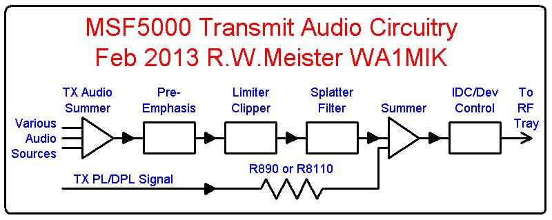
If we could increase the value of R8110, we could decrease the PL deviation level. But to increase the value we need to remove R8110 and install a higher value resistor, not a trivial job because it involves removing the SSCB from the plastic control tray, locating the part, removing it, and having another suitable part to install in its place. There ought to be an easier way.
In the analog stations, a custom hybrid IC performs the digital-to-analog and low-pass functions, feeding a PL/DPL signal in via R890 on the analog SCM, where it joins regular audio at the IDC control.
One Solution:
While we can't easily increase the value of R8110, we can decrease the value of R8108, and it can be done from the top of the SSCB. As the top is accessible, we can tweak our own resistor values in real time if necessary.
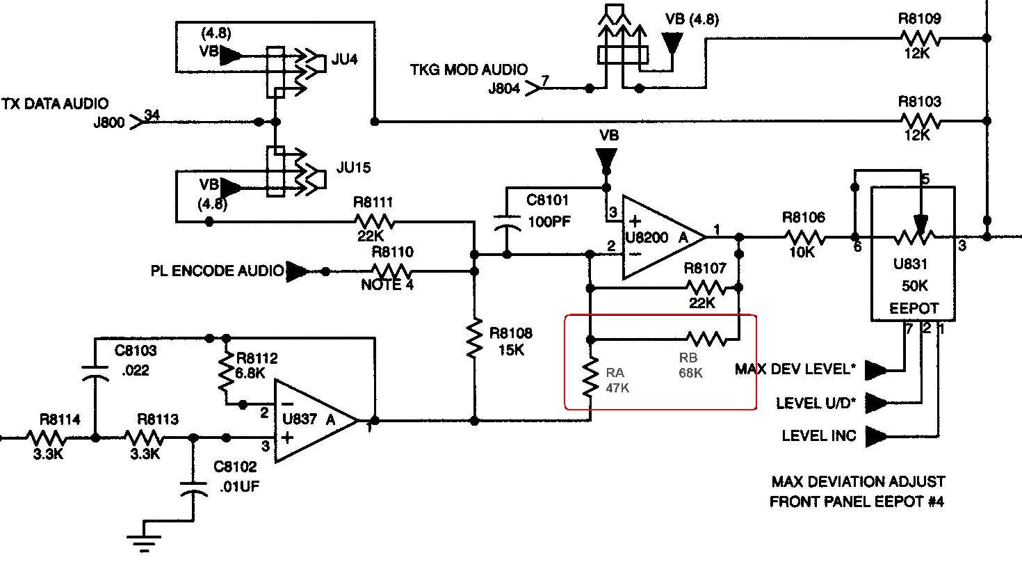
If R8108 is decreased, the voice audio level will be increased, requiring the main deviation to be decreased to maintain 5 kHz deviation. Lowering the main deviation will also lower the PL deviation, so we achieve our goal. But is there a way to decrease the main deviation without having to adjust the EEPot? We can lower the value of R8107, which controls the gain of the amplifier stage just ahead of the EEPot. If the value of both R8108 and R8107 are decreased by the same percentage, the result should be nearly equal voice deviation while the PL deviation is reduced by that percentage. Here's a table showing the math. Note that the values shown are for the later model SSCB.
| Part# | Value | Added | New | Ratio |
|---|---|---|---|---|
| R8108 | 15K | 47K | 11.37K | 0.758 |
| R8107 | 22K | 68K | 16.62K | 0.755 |
The older model SSCB has a different design and both R8108 and R8107 are 10K. Adding a 33K resistor across each one will have the same effect of lowering their values to about 0.767 of the original value.
My ultimate goal is to lower the PL deviation while maintaining the total deviation at the same level as it was originally, thus requiring no adjustments.
Implementation:
There are two styles of digital-capable SSCB - old and new. It's important that you determine which one you have before making the modification. The old style has a small round choke (L803) that looks like an electrolytic capacitor, installed just above and over the left end of U8200. The new style did away with this choke.
Old-style SSCB:
Here's an image showing the location of the parts. The SSCB is in the control tray, flipped up into its service position, with the front panel towards the right. Pin 1 of U837 is marked with a red square.
Add a 33k 1/4w resistor from U837-1 to U837-6, across R8108. This lowers the effective value of R8108 to 7.67k, 76.7% of its original 10k value. By itself, this will raise the audio level with respect to the PL level, and will require readjustment of the deviation pot. To compensate, add a 33k 1/4w resistor from U837-6 to U837-7, across R8107. This lowers the effective value of R8107 to 7.67k, 76.7% of its original 10k value. This will lower the overall audio feeding the deviation pot and should eliminate the need to adjust the pot. This should reduce the PL level to about 77% of its original 700-850 Hz, down to between 540-655 Hz. These new components are outlined in the diagram below.

The station I tried this on has the old style SSCB. I just tacked the resistors onto the pins of the ICs and left them flying free, but if this was going to be permanent, I'd cut the leads short enough and insulate them, so the parts lie on top of the ICs and can't move around very much.
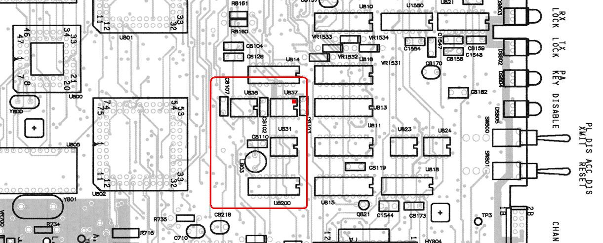
New-style SSCB:
Here's an image showing the location of the parts. The SSCB is in the control tray, flipped up into its service position, with the front panel towards the right. Pin 1 of U837 and U8200 is marked with a red square.

Add a 47k 1/4w resistor from U837-1 to U8200-2, across R8108. This lowers the effective value of R8108 to 11.37k, 75.8% of its original 15k value. By itself, this will raise the audio level with respect to the PL level, and will require readjustment of the deviation pot. To compensate, add a 68k 1/4w resistor from U8200-1 to U8200-2, across R8107. This lowers the effective value of R8107 to 16.62k, 75.5% of its original 22k value. This will lower the overall audio feeding the deviation pot and should eliminate the need to adjust the pot. This should reduce the PL level to about 75% of its original 700-850 Hz, down to between 530-640 Hz. These new components are outlined in the diagram below.
Analog Station Modification:
There's no reason why a similar mod can't be done on the analog SCM. On UHF stations, PL tone comes in via JU14 through R890. You could remove jumper JU14 and insert a resistor to decrease the PL tone level, then adjust the IDC potentiometer to compensate. 800/900 MHz stations don't route the PL tone through JU14 so performing a similar adjustment would be a bit more difficult. The jumper is inside the outlined area on the UHF board x-ray view below.
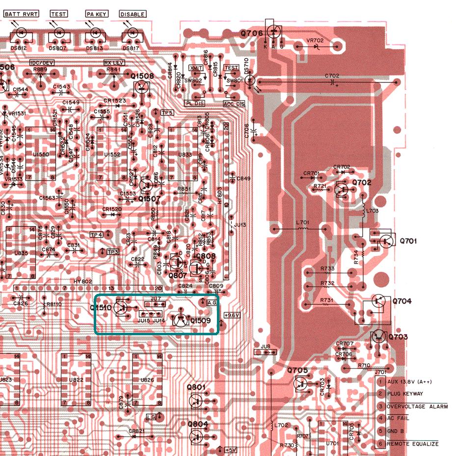
The schematic shows R890 in series with JU14, but the jumper is accessible from the top whereas R890 is soldered under the SCM. Here's the schematic of that part of the circuit.
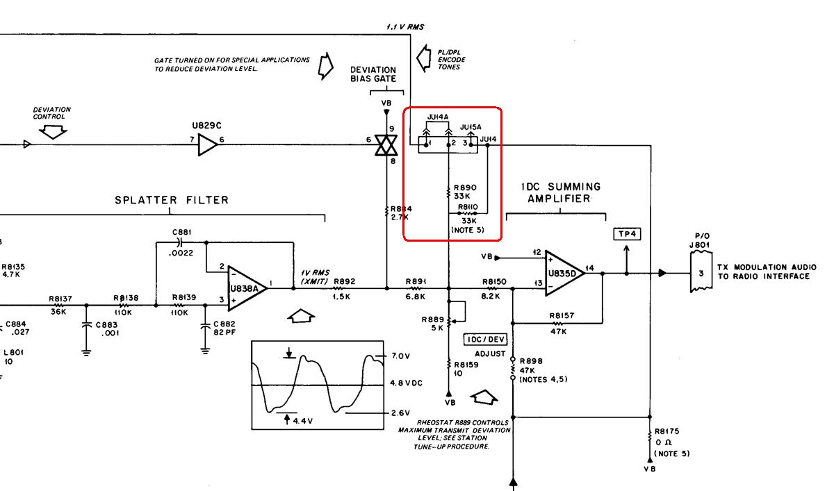
Kevin W3KKC suggests raising the total value of R890 and whatever you insert in place of JU14 to 47K, which means adding a 15K-22K resistor, however I don't have any "before and after" deviation measurements to confirm this value.
Measurements:
I connected a diagnostic metering panel to the station so I could activate the transmitter manually via the LOC PTT MUXBus signal. I measured the PL deviation without any other modulation. I measured the total deviation by injecting a 1 kHz audio tone through a 10uF capacitor into the SSCB at TP8; I set the audio level to produce 4.00 kHz, which was below the clipping level. Then I added the resistor across R8107 and repeated the measurements without changing anything except disabling the audio tone. Finally I added the resistor across R8108 and took the measurements again. The results are summarized in the table below. The deviation values are in kHz.
| Conditions | PL Dev | Total Dev | Notes |
|---|---|---|---|
| Stock | 0.830 | 4.00 | Original station values |
| R8107 Mod | 0.640 | 3.00 | Lowered total deviation |
| R8108 Mod | 0.640 | 3.80 | Raised voice audio only |
So, the PL deviation dropped from 830 to 640 Hz, about 77% of the original value. The overall deviation dropped from 4.00 to 3.80 kHz, a change of about 5%, and this could have been corrected by using a slightly smaller resistor across R8108. A smaller resistor across R8107 will lower the total deviation, whereas a smaller resistor across R8108 will raise the voice audio level with respect to the PL level. Remember that the total deviation in this article is NOT the maximum possible deviation of the station; I purposely set the modulating tone level to produce a total deviation of 4.00 kHz as a reference. The maximum deviation under limiting conditions is 5.00 kHz.
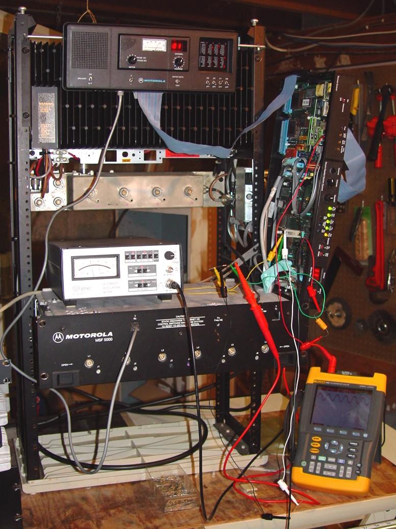
I used an oscilloscope to verify the signals. Not visible is the RF signal generator on the floor that provided the 1 kHz audio tone. The deviation meter is sitting on top of the RF Tray and the diagnostic metering panel is hanging at the top of the station. I've got an IC test clip attached to U837 and clip leads make all the external connections. The photo shows the station transmitting at 4.00 kHz deviation (into a dummy load, of course).
I experimented with the resistor values to see what effect they had. There is some interaction between them. If you have some potentiometers or a good selection of resistors, you can set the PL deviation as low as you want. You can't reduce the gain too much or else the power-on self-tests may fail. The deviation values are in kHz.
| R8107 | R8108 | PL Dev | Total Dev |
|---|---|---|---|
| None | None | 0.830 | 4.00 |
| 10K | 12K | 0.420 | 3.40 |
| 33K | 22K | 0.580 | 3.40 |
| 10K | 10K | 0.420 | 3.70 |
| 22K | 22K | 0.620 | 3.70 |
| 10K | 8.9K | 0.440 | 3.80 |
| 33K | 33K | 0.640 | 3.80 |
| 12K | 10K | 0.460 | 4.00 |
| 15K | 12K | 0.530 | 4.10 |
| 12K | 8.9K | 0.460 | 4.20 |
| 22K | 33K | 0.680 | 4.20 |
Eric WB6FLY suggested I try to get the PL deviation level down to the 400-500 Hz range. I inserted 10K resistors, giving me a theoretical ratio of 0.5, and that nearly cut the PL level in half but it didn't quite return the total deviation to its original value. I tried several other combinations shown in the table above. The 8.9K value was made with a 22K resistor in parallel with a 15K resistor.
I suggest that you measure the PL deviation level first, decide what value of PL deviation you want, figure out the ratio, choose a value of resistor to go across R8107 to give you that ratio, then use a slightly lower value of resistor to go across R8108. For my station that originally produced 830 Hz of PL deviation, I'd want a ratio of 500/830 or 0.60. To reduce R8108's 10K value to 6K, I need to add a 15K resistor across it. I would then try a 12K resistor across R8107. If you have to adjust the overall deviation slightly, that's not such a big deal.
Acknowledgements and Credits:
Eric WB6FLY originally brought this topic to my attention; he ran across it on a Yahoo group. Coincidentally, Kevin W3KKC inquired about adjusting the PL level on the analog station the very same day.
Schematic and component layout diagrams came from the Motorola MSF5000 Instruction and Service manuals.
PL, DPL, and MSF5000 are most likely registered trademarks of Motorola, Inc.
Contact Information:
The author can be contacted at: his-callsign [ at ] comcast [ dot ] net.
Up one level (MSF index)
Up two levels (Moto index)
Back to Home
This article first posted Feb 22, 2013.
Article text, photos, and hand-coded HTML Copyright © 2013 by Robert W. Meister WA1MIK.
This web page, this web site, the information presented in and on its pages and in these modifications and conversions is © Copyrighted 1995 and (date of last update) by Kevin Custer W3KKC and multiple originating authors. All Rights Reserved, including that of paper and web publication elsewhere.