Up one level (MSF index)
Up two levels (Moto index)
Back to Home
|
|
Interfacing an ACC RC-850
Repeater Controller to an
MSF5000 CXB Station
Originally titled:
Specifications Covering the Line-up and
Installation of the VHF Motorola MSF5000
(possibly published by ACC itself)
Transcribed by Robert W. Meister WA1MIK
(with some corrections and improvements)
|
|

|
Disclaimer from WA1MIK:
The original author and source are unknown. This document was something I found
on the web and printed in 2002 and stuffed into a binder. It is incomplete and there
are lots of omissions and errors. I merely transcribed it. You get what you pay for.
See the "Contacting Us" page on the Repeater-Builder main index page if you can offer
improvements or corrections.
Purpose:
This document summarizes the changes in configuration as well as the interface
specifications for a VHF Motorola MSF5000 in order to be used with the ACC RC-850
repeater controller.
Equipment:
The equipment covered by this specification is as follows.
- Motorola VHF MSF5000 Model C73CXB7106BT (secure capable with trunked
tone remote control option installed)
- Motorola TLN4704A Directional Coupler
- Motorola TPN1218A Power Supply
Software Configuration:
"SoftPot" settings for initial installation were changed as follows.
| SoftPot | Signal Being Adjusted | Original | Modified |
| 0 | Coded (Decrypted) RX Level |
50 | 00 |
| 1 | Flutter Fighter Level (896 MHz only) |
10 | 00 |
| 2 | Repeater Squelch Level |
78 | 78 |
| 3 | Receiver Squelch Level |
73 | 73 |
| 4 | Maximum Deviation Level |
82 | 82 |
| 5 | Receiver (Repeater) Level |
99 | 99 |
| 6 | Coded Deviation Level |
89 | 00 |
| 7 | Transmit Line Audio Level |
41 | 00 |
| 8 | Status Tone Level |
50 | 00 |
| 9 | High End Equalization Level |
00 | 00 |
| A | Low End Equalization Level |
00 | 00 |
| B | Trunking Data Deviation Level |
00 | 00 |
| C | Line 2 Output Level |
50 | 00 |
| D | Line 4 Output Level |
00 | 00 |
| E | Coarse Line Output Level |
02 | 00 |
[The following paragraph added by WA1MIK:]
You must enable the MRTI interface port on page 6 of the Advanced Information
settings. You must also add "M" (MRTI) to the PTT Priority field list and set the
MRTI TOT (Time-Out-Timer) field to 000 for the mode being used by the repeater.
There are other configuration parameters that also must be set when using an
external repeater controller. All of these settings are changed using the Radio
Service Software (RSS).
Hardware changes from the original configuration (as purchased)
Secure Capable Station Control Board (SSCB):
- JU2 Moved to Normal Position. This jumper selects whether the HSR data is
routed to the Secure Board or not. [Ed: Normal position is No Board Installed.]
- JU3 Moved to Normal Position. This jumper selects whether coded mod audio is
injected into the TX path or not. Normal position is not.
- JU5 Moved to Alternate Position. This jumper selects whether TKG mod audio is
injected into the TX path or not. Alternate position is not.
- JU10 Moved to Normal Position. This jumper selects whether secure RX audio is
enabled or not. Normal position is not.
Trunked Tone Remote Control Board (TTRC):
- Cable harnesses for external connections were disconnected and saved.
- Reconnecting the cables is a matter of matching the color code on the RJ12
jacks and connecting the Molex connector to the appropriate connector on the
TTRC board.
Secure Module:
- Cable harness connected to J4001 removed and saved.
- This cable is the KVL interface cable for loading secure keys into the secure
module.
- The TLN3045B Secure board was disconnected and removed.
- As a result, JU2 on the SSCB was moved to the Normal position to loop back
HSR Data properly.
- This board and associated cable were sold.
Interface Specifications:
Upon researching the various options for interfacing the control and audio lines
from the RC-850 to the MSF5000, it was determined that using the MRTI interface
connector on the MSF5000 was the most effective option. It was also decided to
combine all of the audio and control lines to and from the MSF5000 into a female
DE-9 connector to be mounted to the chassis. This was done in order to assist in the
ease of installation and removal of the MSF5000 or the RC-850.
The pinout of the MRTI (J802) connector is as follows. Click on the image for a
larger view.
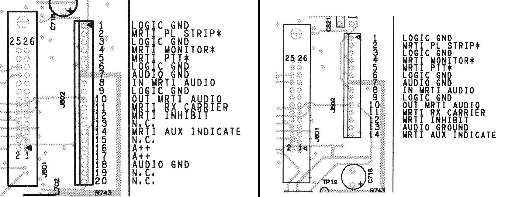
Note that this connector can have either 20 pins (older board) or 14 pins (newer
board), but the usage of the first 12 pins is the same. The pins used on this
connector are as follows.
| Pin | Signal Name | Use or Function |
| 1 | Logic Ground |
Ground connection used as reference for logic connections. |
| 2 | MRTI PL Strip* |
Active low input. Tied to Autopatch Offhook output from RC-850. Allows
DPL transmitted during normal operation to be turned off during an autopatch call to
facilitate selective monitoring. |
| 5 | MRTI PTT* |
Active low input. Used as PTT input from RC-850 to key transmitter. |
| 7 | Audio Ground |
Ground connection used as reference for audio connections. |
| 8 | In MRTI Audio |
Audio in from RC-850 to be transmitted. |
| 10 | Out MRTI Audio |
Audio out to RC-850 from receiver. |
The pinouts of the TTRC connectors (J2900 and J2901) are as follows. Click on the
image for a larger view.
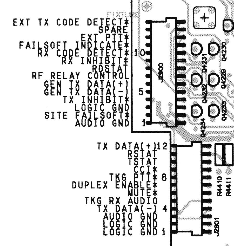
Most of the pins used for the interface to the RC-850 are available from the MRTI
connector (see above). However, one pin that is required but is not available on that
connector is some sort of Carrier On Receive (COR) signal.
That signal is available as either active low or active high as required. The pins
involved are:
- J2900, pin 3: Logic Ground
- J2900, pin 8: /RDSTAT (active low)
- J2901, pin 2: Logic Ground
- J2901, pin 11: RSTAT (active high)
The only other signal required is an external keying signal (/PA KEY) for the power
amplifier. This signal is active low and is available from the RF Tray Interconnect
Board on either J502A, pin 6 or J596A, pin 4 as desired. Ground, if required, is
available at J502, pin 5 or J596A, pin 3.
[The following paragraph added by WA1MIK:]
I don't know why they need the external keying signal described in the paragraph
above. This signal isn't brought out to the DE-9 connector or the RC-850 controller
via the interface cable below. They DO seem to want /AC FAIL, an active low signal
that comes from the power supply. This IS available on the RF Tray Interconnect Board
at J701A, pin 4 as documented below.
DE-9 Connector Pin Specifications:
The pinout of the DE-9 connector added to the MSF5000 chassis for interfacing to
the RC-850 is as follows:
| DE-9 | MSF5000 | RC-850 |
Description |
| 1 | J802, 7 | DA-15, 2 (AGND) | Audio Ground |
| 2 | J802, 8 | DA-15, 1 (J10, 10) | Audio From RC-850 |
| 3 | J802, 10 | DA-15, 9 (J10, 2) | Audio To RC-850 |
| 4 | J2900, 8 | DA-15, 8 (DGND) | Logic Ground |
| 5 | J2900, 3 | DA-15, 7 (J6, 17) | /COS |
| 6 | J701A, 4 | (J6, 14) (Digital Input) | /AC Fail |
| 7 | J802, 1 | DA-15, 8 (DGND) | Logic Ground |
| 8 | J802, 5 | DA-15, 5 (J6, 7) | /PTT |
| 9 | J802, 2 | (J7, 8) (Digital Output) | /DPL Disable |
RC-850-MSF5000 Interface Cable Specifications:
The cable below was constructed to interface the MSF5000 to the RC-850. A resistor
divider network was used to reduce the audio to the RC-850 from about 6.4 Vpp to 1
Vpp (at 1kHz).

Up one level (MSF index)
Up two levels (Moto index)
Back to Home
This article transcribed 03-Dec-2011.
This web page, this web site, the information presented in and on its pages and
in these modifications and conversions is © Copyrighted 1995 and (date of
last update) by Kevin Custer W3KKC and multiple originating authors. All Rights
Reserved, including that of paper and web publication elsewhere.