Up two levels (Moto index)
Back to Home
Electrolytic Capacitors
on the MSF5000 Uniboard
and Injection Amplifier
By Robert W. Meister WA1MIK

|
Up one level (MSF index) Up two levels (Moto index) Back to Home |
Replacing the Electrolytic Capacitors on the MSF5000 Uniboard and Injection Amplifier By Robert W. Meister WA1MIK |
|
The Uniboard is the main board in the RF Tray. It occupies most of the top of the RF Tray and is the first board you encounter when you remove the top cover. Refer to the MSF5000 Photo Tour article to locate this board. It contains:
Sooner or later you might start having problems with the station that can be traced back to the Uniboard. Just this year I had two different issues with two stations:
With the first station, I didn't know if it was the VCO or the synthesizer/PLL that was acting up. I managed to acquire another Uniboard and swapped that first. The VCO locked fine and stayed that way, so I knew that's where the problem was. To be sure, I put the original board back in and swapped the VCO; the LOCK LED did not come on.
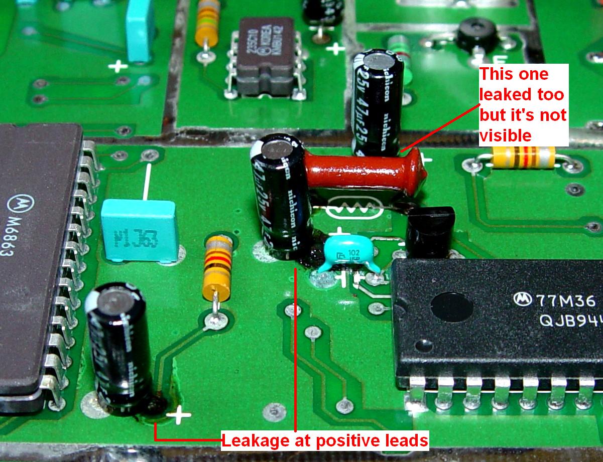
Since the original Uniboard was out of the station, I could now see that half a dozen electrolytic capacitors had leaked. On this board, all of the parts hang down underneath it, but the leakage had crawled up the leads against gravity and left a puddle of black material on the circuit board itself. All of the leaking caps were in the synthesizer and PLL circuits, mostly used as filtering. Replacing all 18 visible caps fixed it right up. The two caps hidden under a shield were eventually replaced as well and tested perfect. Here's a photo of some of the leakage on the Uniboard (at capacitors I numbered 4, 5, and 6 in the list below). All of the photos are quite large. Click on any photo for a larger view.
With the second station, there was no visible evidence of bad caps. I viewed the output of the receiver mixer where it enters the Uniboard and saw the 10.7 MHz IF signal there, however it was a saw-tooth waveform that deviated ±40 kHz at a 1.2 kHz rate. I should have seen a single unmodulated signal. There are two signals feeding the mixer: the input signal from the antenna jack, which was an unmodulated clean signal at 0dBm, and the local oscillator signal, also an unmodulated signal that starts at the receive VCO and gets amplified by the injection amplifier to +28dBm. I viewed the output of the injection amplifier and found a saw-tooth waveform that deviated ±40 kHz at a 1.2 kHz rate, so I knew that the local oscillator signal was the source of the problem.
I also viewed the transmit VCO signal and found a similar saw-tooth waveform that deviated ±40 kHz, but at a much faster rate, around 10 kHz. Figuring I had nothing to lose, I replaced all 18 visible electrolytic capacitors on that board; that fixed it right up. After I replaced them, I tested all of the original caps; all had no measurable capacitance. The two hiding under a shield were just as bad.
Another UHF station appeared to be working fine and the meter readings hadn't changed in several years, but the battery-reverting power supply died. After swapping the supply, I removed the Uniboard and found very slight leakage on just a few caps, so I decided to replace them all.
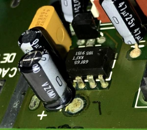
Here's another photo taken by Bruce NW5S of caps on his Uniboard. His UHF station had synthesizer/VCO problems and the tuning meter indication was stuck at 50 and would not change when he tried tuning the VCO slug. While his didn't have the black gunk on the circuit board like mine did, the solder pads are still corroded and the caps themselves need to be replaced.
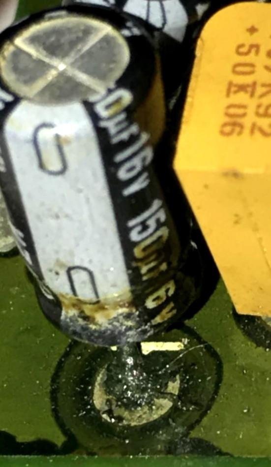
Another sign of leakage can be seen in the photo below.
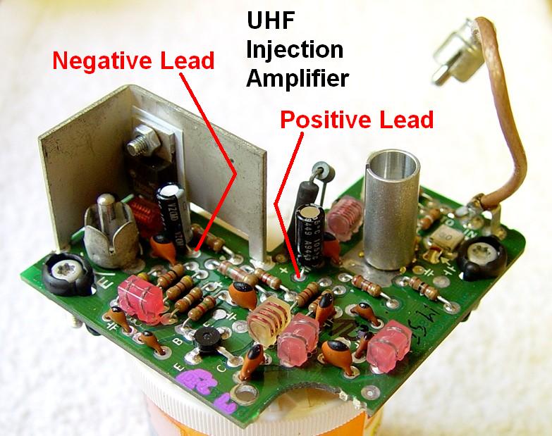
The injection amplifier is a small board that sits to the left of the Uniboard. It takes the signal from the receive VCO and amplifies it to almost 1 watt to feed the mixer. There are a couple of electrolytic capacitors on the UHF and 900 MHz versions. If you're going to replace the caps on the Uniboard you might as well buy two more and replace the ones on the injection amplifier too.
Removing the Uniboard:
To insert the Uniboard, follow the steps in reverse. Be very careful that the pins sticking up from the RF Tray are properly aligned with the sockets in the Uniboard. It should fall into place but you don't want to force it. Once it's lined up, gently press down on the rear edge of the board to seat the connectors. Also make sure the plastic standoffs are in place. Reconnect all the cables and connectors.
Dealing with the Injection Amplifier:
This is one of the simpler boards to remove, especially if the Uniboard is already out. Unplug the coaxial cables, remove two captive T15 Torx screws, and lift the board out. Replacement is just the opposite. Nothing is really critical here. My board had two 10uF, 35V caps but you can use 10uF, 25V caps, the same as the ones on the Uniboard, so if your station needs them, just order two more. Note the orientation; this board isn't as well-marked as the Uniboard. Here's the UHF injection amp.
TRN7231A Uniboard Electrolytic Capacitors:
In the table below, "My#" refers to the left-to-right part number that I assigned to the caps in the photo of the board. "Pg#" refers to the PDF page number of the Uniboard manual section that you can retrieve here. "Circuit Function" is what I believe to be the circuit that the capacitor is used in. Remember, these lists are ONLY for the TRN7231A Uniboard, which has lots of surface-mounted components on the solder side and lots of empty space on the top. Unfortunately the X-ray view for the TRN7231A show leaded resistors, which doesn't match the boards I have.
| My# | Cap # | Cap Value | Pg# | Circuit Function |
|---|---|---|---|---|
| 1 | C364 | 4.7uF, 50V | 8 | Mod Comp (SEE NOTE) |
| 2 | C412 | 47uF, 10V | 19 | Driver Fwd Voltage |
| 3 | C368 | 10uF, 25V | 8 | Modulation Compensation |
| 4 | C335 | 47uF, 25V | 8 | 5v U322 |
| 5 | C344 | 47uF, 25V | 9 | Ramp Generator |
| 6 | C339 | 47uF, 25V | 9 | 5v U323 |
| 7 | C326 | 47uF, 25V | 7 | Vbb U321 |
| 8 | C415 | 10uF, 25V | 21 | Signal 'Q' |
| 9 | C363 | 47uF, 25V | 9 | Signal 'D' |
| 10 | C369 | 100uF, 25V | 7 | 9.6V Supply Filter |
| 11 | C360 | 10uF, 25V | 9 | Voltage Regulator |
| 12 | C362 | 47uF, 25V | 10 | Voltage Regulator |
| 13 | C275 | 47uF, 25V | 12 | 5v U262 |
| 14 | C284 | 47uF, 25V | 13 | Ramp Generator |
| 15 | C279 | 47uF, 25V | 13 | Ramp Generator |
| 16 | C266 | 47uF, 25V | 11 | Vbb U261 |
| 17 | C308 | 150uF, 16V | 14 | Voltage Regulator |
| 18 | C306 | 10uF, 25V | 13 | Voltage Regulator |
| 19 | C257 | 10uF, 25V | 18 | FM Detector (under shield) |
| 20 | C200 | 10uF, 25V | 18 | FM Detector (under shield) |
NOTE: C364 (My #1) was marked 4.7uF on the first Uniboard I repaired, so that's what I put in. It was marked 47uF on the second Uniboard but I just duplicated the first order and installed a 4.7uF cap there. Another MSF5000 user reported all of his caps were leaking so badly they were wet, and his board has a 47uF cap there. Some service manuals call for a 47uF cap, others say 4.7uF. It turns out that Product Support Bulletin 726 (available on this web site) covers this change. Boards shipped after 01-Feb-1994 have the 4.7uF cap; those shipped earlier have the 47uF cap. A 4.7uF cap is installed for improved low-frequency (i.e. trunking data and DPL) operation of the modulation compensation circuit. The first board I fixed came from a station that was shipped in late 1994, so it had the 4.7uF cap.
Here's a summary of the caps along with Digikey part numbers. Remember to buy two more 10uF, 25V capacitors if your station's injection amplifier uses them.
| Cap. Value | Qty | Digikey Part # |
|---|---|---|
| 4.7uF, 50V | 1 | P15839CT-ND |
| 10uF, 25V | 6 | P15799CT-ND |
| 47uF, 10V | 1 | P14478-ND |
| 47uF, 25V | 10 | P15141-ND |
| 100uF, 25V | 1 | P10269-ND |
| 150uF, 25V | 1 | P14414-ND |
Here's a photo of my UHF Uniboard with my numbers adjacent to the electrolytic capacitors.
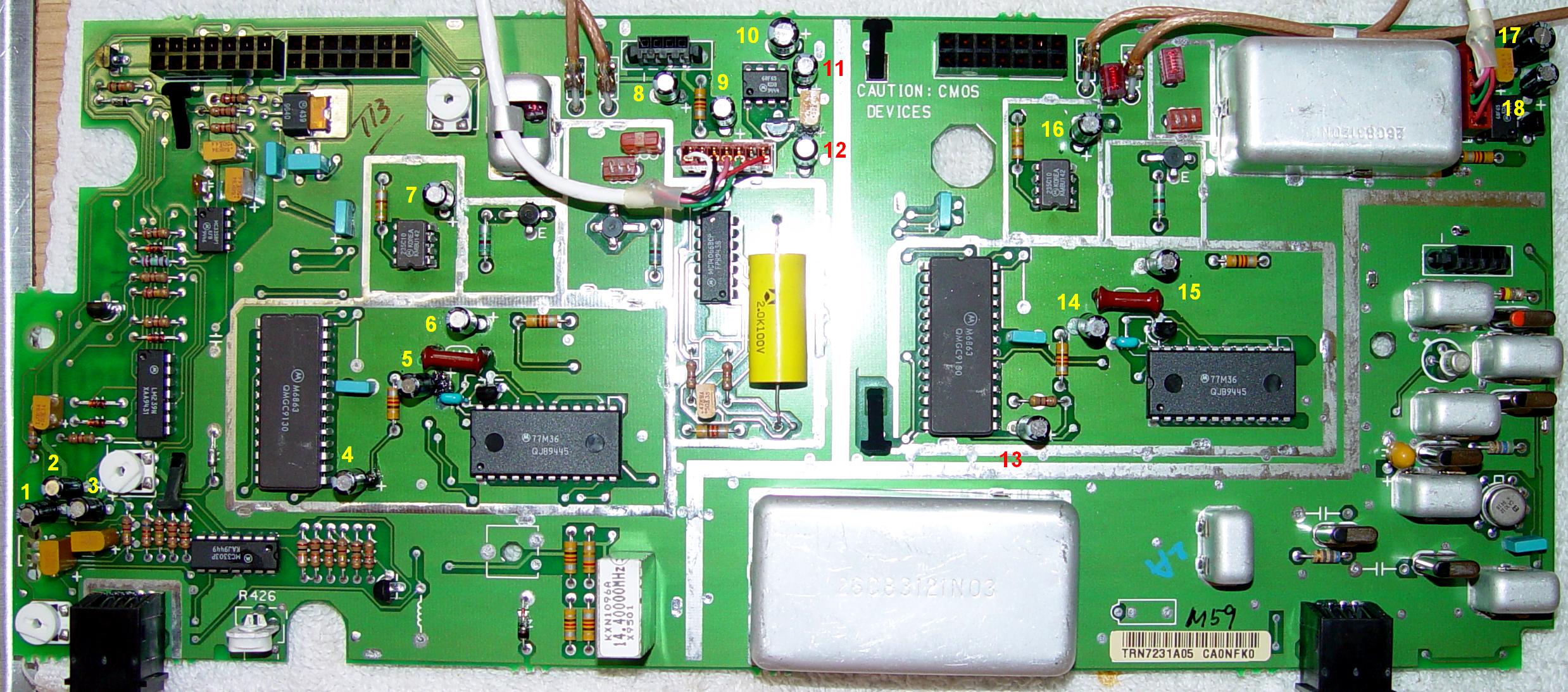
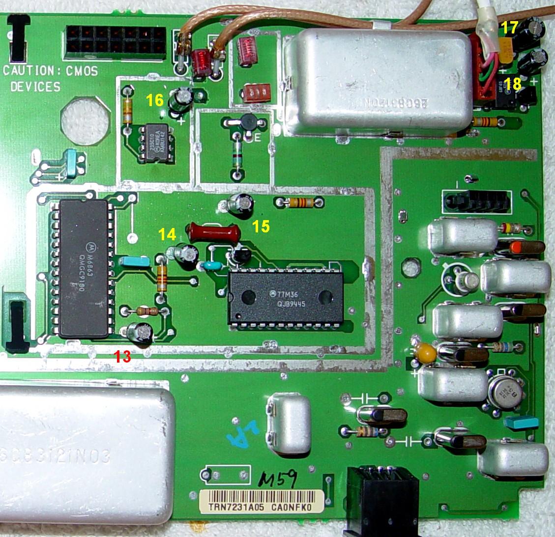
The photo is rather wide, so I've split it up into two halves. First the left half,

then the right half.
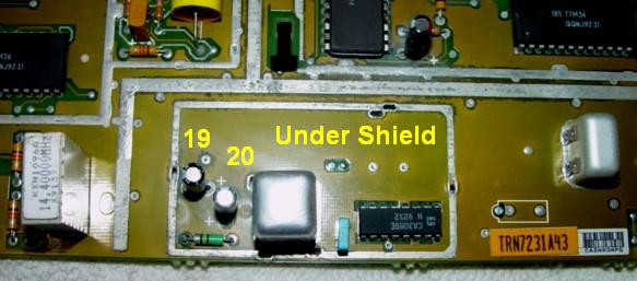
After unsoldering and removing that central shield, I found two more capacitors.
Capacitor Replacement Hints:
On the last board I recapped, I started by removing the shields. The bottom shield just snaps off but the top shield is soldered to the board in four places. I was able to suck some solder out of each hole but I had to use my 100/140w Weller soldering gun to heat both sides of the board as well as the tab attached to the shield. I could then pry the shield gently and go around to each tab until it moved out of its hole. Once I got the shields off, the caps were easily replaced (well, as easy as any other exposed cap). It took me over an hour to remove the shields, replace the two caps (#19 and #20) under them, put the shields back on, and replace another seven capacitors (#1 thru #7). I expect it will take me another hour to replace the remaining 11 caps then I'll do the injection amplifier board.
Because of the ground foil on the top of the board, removing the capacitors without breaking their leads isn't that easy. I found that I could heat the positive lead and bend the cap over on its side and pull that lead out of its solder hole, then do the same with the negative lead. After that I could suck the solder out of each hole by adding a bit of fresh solder first, especially on those holes that had endured leakage. It was much easier to suck the solder out of the holes without the capacitor's leads in them. Even after all of that, several holes had to be cleaned from both sides.
Replace one capacitor or group of capacitors at a time, in the order I've numbered them, so you don't make any errors. Observe the polarity. It may help if you take two detailed photos of your board so you can refer to them while replacing the caps. Clean both sides of the board with 91% isopropyl alcohol and a tooth brush after you remove the old cap; it'll make installation and cleanup of the new cap much easier. Clean the bottom of the board after you solder each group.
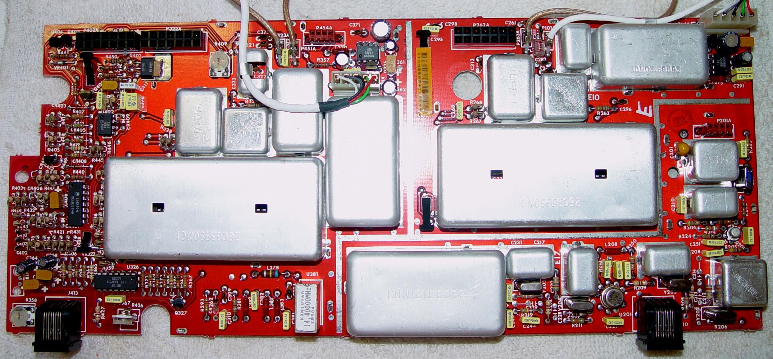
There are lots of Uniboard model numbers. The parts designations, values, and locations may be different, so make your own list, check it twice, and order the exact values needed for your board. The component designation and polarity are nicely indicated on the solder side of the board. One such board is the TRN9880A, which is partially documented here and more completely here. I have one of these boards (made in late 1988 and it looks like it's not even a day old) and about 80% of both sides are covered with shields that would need to be removed to access all the capacitors. All of the bottom shields have handles and can easily be popped off, but most of the top shields (two are missing handles) are soldered into the board in at least one spot. As it is, only eight caps are visible and I'm sure the rest hiding, probably four per synthesizer. I located and identified 16 capacitors from the schematic and X-ray view but I wouldn't trust the values listed in the manual. All of the components are on one side and it has lots of 1/4w leaded resistors standing on end. Here's a photo of that board.
Of course, other bands have their own unique Uniboards too. It's best to examine each electrolytic capacitor, make a list of values, and order what you need for your board.
After you replace these capacitors, particularly if C364 changed value, you should go through the deviation and modulation compensation adjustments and make sure the squelches are still closed.
Credits and Acknowledgements:
Photos were taken by the author.
Component designations came from the Motorola MSF5000 Service Manual.
Thanks to Jeff WN3A for suggesting I look at the VCO signals and IF input with the spectrum analyzer.
Thanks to Bob WA2VDX for persisting in finding out why C364 was a different value and discovering PSB726.
Thanks to Bruce NW5S for sending in photos of the leaky caps on his Uniboard.
Contact Information:
The author can be contacted at: his-callsign [ at ] comcast [ dot ] net.
Article text, photographs, and hand-coded HTML © Copyright 2015 By Robert W. Meister WA1MIK.
Up one level (MSF index)
Up two levels (Moto index)
Back to Home
This article was created 30-Jul-2015
This web page, this web site, the information presented in and on its pages and in these modifications and conversions is © Copyrighted 1995 and (date of last update) by Kevin Custer W3KKC and multiple originating authors. All Rights Reserved, including that of paper and web publication elsewhere.