Up to the main Moto index
Back to Home
Motorola MSR2000
VHF Repeater
By Ron Wright N9EE

|
Up one level Up to the main Moto index Back to Home |
Running D-STAR on a Motorola MSR2000 VHF Repeater By Ron Wright N9EE |
|
The MSR2000 can be configured to pass and repeat D-STAR data. Simply taking the data from the discriminator is fine for the receiver. But as with most FM radios, the audio input is processed (clipped, filtered, pre-emphasized) to the point that the D-STAR data gets distorted, preventing user's radios from properly decoding it. Transmit data level and cleanliness is the big issue for D-STAR.
The D-STAR system needs a direct Frequency Modulated transmitter because D-STAR's digital data is used to frequency-shift the signal. A Phase Modulated transmitter will distort the data, making it unusable. Fortunately, the MSR2000 uses true Frequency Modulation and makes a good D-STAR candidate, so you have nothing to worry about.
MSR2000 Transmitter Interface:
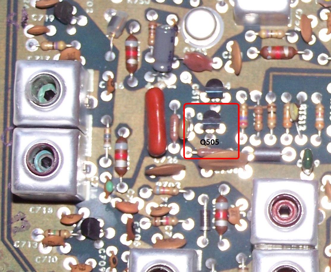
Apply the D-STAR data to the MSR2000's exciter at Q505, directly into the base, through an isolation network described below, and the MSR2000 will pass the data cleanly. The base of Q505 can be jumpered to an unused pin on the exciter back plane connector providing an easy point to insert the data. You can install the isolation network components on the exciter card too. One unused pin for a repeater would be one of the exciter's Fx Select pins, since most repeaters have a need for only one frequency. Click on any photo for a larger image.

The photo below is a closeup of the left side of the above image with Q505 indicated. The base is the middle lead of Q505. Consult the VHF Transmitter manual on this web site for more details.
For Push-To-Talk (PTT), there are several spots available, however I connected the DRC to the backplane slot 2 (Station Control Card) pin 5 (pull low to key).
MSR2000 Receiver Interface:
The DRC input comes directly from the MSR2000's receive discriminator found at J201 pin 5 on the MSR2000's back plane. Run this signal through the isolation network described below.
Receiver and Transmitter Audio (Data) Isolation Network:
Couple all audio signals through a 1uF 16V (or larger) non-polarized capacitor with a 1k resistor in series. If you can't find a non-polarized capacitor, use two 2.2uF capacitors connected in series with their positive ends tied to each other.
The ARS D-STAR Repeater Controller (DRC):
A D-STAR controller that works very well is the D-STAR Repeater Controller (DRC) from Advanced Repeater Systems. This controller is designed to recognize D-STAR data, condition and delay the data by 250 milliseconds (to give all radios time to stabilize and lock onto the signal), and provide a PTT signal (pull to ground) when the controller senses D-STAR data. Here's a photo of the DRC:
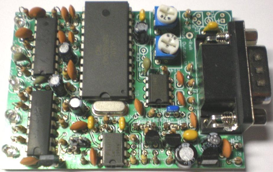
The DRC can be interfaced to any repeater through a DE-9P connector. Main connections are: 12VDC, ground, receiver discriminator, transmitter PTT (pull to ground) and transmitter data.
Setting Levels:
All level adjustments are done on the DRC. The input level is set with pot PT2 to 1 Vp-p at test point "RX A". Transmitter level/deviation is set to 1.2 to 1.5 kHz with pot PT1 using a service monitor. Exceeding this level can prevent user's receivers from decoding the data.
An alternative is to use an ICOM D-STAR hand-held or mobile radio signal as a reference and set the repeater's output to match this level.
D-STAR Data Problems:
Other issues with D-STAR is the data must be "right side up" or not inverted as can occur in some receivers and exciters.
D-STAR data is frequency shift keyed with a logic 1 (one) being 1 kHz above the carrier frequency and a logic 0 (zero) being 1 kHz below the carrier. The D-STAR data must be in this configuration so the receiving station radio knows when there is a 1 or 0 in the data.
The DRC has a jumper to invert the data output in the event a repeater does invert the data. This jumper is not needed for the MSR2000, but may be needed in other repeaters.
Contact Information:
Ron is the owner of Micro Computer Concepts (MCC). He is not affiliated with
ARS.
He can be contacted at: mccrpt [ at ] tampabay [ dot ] rr [ dot ] com.
Back to the top of the page
Up one level
Up to the Motorola index
Back to Home
Original article posted 22-Dec-2014.
This web page, this web site, the information presented in and on its pages and in these modifications and conversions is © Copyrighted 1995 and (date of last update) by Kevin Custer W3KKC and multiple originating authors. All rights are reserved, including that of paper and web publication elsewhere.