Up two levels (Main Moto Index)
Back to Home
CAT200B Controller
Interface Cable
By Robert W. Meister WA1MIK

|
Up one level (MTR2000 Index) Up two levels (Main Moto Index) Back to Home |
MTR2000 Station to CAT200B Controller Interface Cable By Robert W. Meister WA1MIK |
|
Interfacing Choices:
There are basically two connectors devoted to interfacing on the MTR2000: the System connector (known as J5), which needs an uncommon 96-pin male connector body and several contacts to mate with J5, and the MRTI Connector (known as J7), which needs a common DB25M connector. Motorola offers a System connector package that has the connector body and a few dozen wires with crimped-on contact pins, but that costs over $50. (People have even fed audio into the wire line inputs, but while the wire line card was normally included with every MTR2000 station, not all will still have one.) I have since found that the connector is more commonly known as a DIN 41612 (Eurocard) 3-row, 96-pin header and is available at the larger parts suppliers for about $5 (Mouser part number 571-5650889-5). It's meant to be pushed through a circuit board, but you'll have to solder wires to the pins. The MRTI connector is cheaper, as a DB25M and hood can be purchased new for under $4; in fact you might already have one in your junk box.
The MSF5000 has an MRTI interface too, but it uses a different connector. I wanted to transplant the CAT controller from my MSF5000 station to my MTR2000 station, so I took the interface cable information from that radio's interfacing article and changed the radio connector to a DB25M and wired it appropriately. I ended up using two signals on the System connector, just like I had to use two signals on the TTRC of the MSF5000 station.
The repeater interface now consists of these five signals on two connectors: TX Audio In, RX Audio Out, PTT In on the MRTI connector, and Rdstat-R2 Control Out (CTCSS), and Carrier Detect Switch Out (COR) on the System connector. Of course, ground and power are always required. I also can put the receiver into carrier squelch mode if necessary.
Using the MRTI Connector for audio and PTT has the additional benefit that the station works as you'd expect it to: PL/DPL is transmitted when the station is keyed via this input, and PL/DPL is stripped from the audio signals to and from the external controller. There are all sorts of horror stories about the lack of PL/DPL when audio and PTT are fed in via the System connector.
Initially I wanted to use only the MRTI connector, but I had problems with one signal and ended up using two signals on the System connector instead. Until I acquire a real 96-pin connector, I just stuffed two leads from a 1/2 watt resistor into the socket to make things work.
Useful Signals on the System connector:
See the MTR2000's Backplane Connectors article for a description and location of these signals and connectors.
I found that pin B4 (Carrier Detect Switch) would go high with an un-coded carrier.
I found that pin C2 (Rdstat-R2 Control) would go high with a coded signal.
There is ground available on pins A27, B27, and C27. When I acquire a mating connector, I will use these for powering the CAT200B controller.
There is +14.1VDC available on pins A32, B32, and C32. When I acquire a mating connector, I will use these for powering the CAT200B controller.
None of the other documented Rdstat pins did anything. I think a Wildcard would have given me additional possibilities but most stations, including mine, don't have one.
HINT: When you get the 96-pin connector, you'll see the pin numbering molded into the rear at each end, and it says pin 32 is on the left. Disregard this information. The row lettering IS correct (row C is on top). The connector will only mate with the one on the MTR2000 in one way, so make sure you put it on the station first, verify pin C1's location (on the upper left looking into the back of the station), and mark this end, then attach your wires. Use heat-shrink tubing over any pins you utilize.
MTR2000 MRTI Connector:
The MTR2000's MRTI Connector is a DB25F. An asterisk (*) after a signal name means it is active low and O.C. means Open Collector. Spare (unused) pins have been omitted from this table.
The signal names came right out of the MTR2000 RSS Help file. The DCV column was measured on an idle station and the Notes were from playing with my own 100w UHF station.
| Pin # | Signal Name | DCV | Notes |
|---|---|---|---|
| 1 | MRTI Tx Audio | 2.4 | Pre-emphasized, 0.4V/kHz at 1 kHz |
| 2 | Trunk MRTI PTT* | 5.1 | Ground for Tx (same as pin 11) |
| 4 | MRTI Monitor* | 5.1 | Ground disables Rx coded squelch |
| 7 | MRTI Rx Audio | 2.4 | De-emphasized and limited to 3 kHz dev. |
| 8 | Patch Inhibit* or RSTAT | 5.1 | (same as pin 25) |
| 9 | GND | 0.0 | |
| 10 | Aux Carrier* or TSTAT | 5.1 | Low when Tx is on (same as pin 12) |
| 11 | Trunk MRTI PTT* | 5.1 | Ground for Tx (same as pin 2) |
| 12 | Aux Carrier* or TSTAT | 5.1 | Low when Tx is on (same as pin 10) |
| 13 | Trunk Tx Data+ | 3.9 | |
| 15 | MRTI Rx Carrier* | O.C. | Goes to ground with properly coded carrier |
| 16 | GND | 0.0 | |
| 17 | GND | 0.0 | |
| 18 | GND | 0.0 | |
| 19 | GND | 0.0 | |
| 21 | Trunk Tx Data- | 0.0 | |
| 22 | Trunk Rx Audio | 4.8 | De-emphasized and limited to 1 kHz dev. |
| 23 | Trunk Mute* | 5.1 | |
| 24 | PL Strip* or CCI* | 5.1 | Ground disables coded Tx |
| 25 | Patch Inhibit* or RSTAT | 5.1 | (same as pin 8) |
The interface cable consists of eight wires and two DB25M connectors with retaining screws. Label the wires going to the System connector, if you don't end up buying a 96-pin connector to mate with it.
The CAT200B I/O Connector is a DB25F. I used three feet of 8-conductor 22-gauge cable that I had on hand. I assigned the wire colors arbitrarily.
| CAT Pin | CAT Signal | Color | MTR2K Signal (active level) | MTR Pin |
|---|---|---|---|---|
| 4 | CTCSS In 1 | Brown | Rdstat-R2 Control (HIGH) | Sys C2 |
| 6 | COR In 1 | Red | Carrier Detect Switch (HIGH) | Sys B4 |
| 10 | PTT Out 1 | Orange | PTT In (LOW) | MRTI 2 |
| 11 | TX Audio Out 1 | Yellow | TX Audio In | MRTI 1 |
| 13 | RX Audio In 1 | Green | RX Audio Out | MRTI 7 |
| 14 | Switch Out 1 | Blue | Monitor In (LOW) | MRTI 4 |
| 17 | Ground | Black | Ground | MRTI 17 |
| 18 | Ground | White | Ground | MRTI 18 |
The audio lines in and out of the CAT controller are already isolated with capacitors, so a simple direct connection to the MTR2000 is all that's needed.
Controller Configuration:
I have installed 10k resistors for both R36 and R37, the two COR input pull-up resistors, on the CAT200B circuit board. CAT says they supplied 2.2k resistors but I thought that was too small. You only need one for COR #1 but I put both in when I first got the unit.
The CAT200B controller has a DIP-switch (SW1) that sets the signal polarity. Set the following positions:
1 - OFF (COR active high)
2 - OFF (CTCSS active high)
Certain zone settings also need to be made:
Zone 1, channel 1 - ON to enable the repeater
Zone 1, channel 2 - ON to enable CTCSS access
Zone 3, channel 3 - OFF to enable CTCSS AND CARRIER
Zone 3, channel 5 - OFF to require coded squelch (normal), ON for carrier squelch
If your system also has an audio delay board (such as the CAT DL1000), make sure the COR input signal polarity is set properly as well. It has to match the setting for the controller, in this case active high.
MTR2000 Configuration:
Since we're using the MRTI interface, it has to be enabled in the RSS. In the Station Configuration screen, make sure the "MRTI Enable" box is checked. In the same screen, you want to set the station up as a base station, NOT a repeater, as the external CAT controller will be doing everything. Further down, make sure the Wireline Board Type, if you have one, is set to one with 4-wire, not 2-wire. In a 2-wire configuration, the receiver is muted when the station is transmitting, because the single pair of wires can only pass audio in one direction at a time.
In the Personality, Channel Information, Audio screen, set the Analog RX Activation to Carrier & PL/DPL. Make sure you check the Pre-Emphasis, De-Emphasis, and MRTI boxes for the active channel. I entered the legal call sign in the CW ID field. Remember that this will be sent by the MTR2000 during a quiet period WITHOUT PL OR DPL, but because the internal CW ID can be pre-empted by any keyup, it's not legal for amateur use, since on a busy repeater the CW ID won't be transmitted until there's at least 10-15 seconds of non-use.
In the Personality, Channel Information, PTT screen, make sure the Timeout boxes are unchecked, as the MRTI input acts as a local PTT. Also, make sure you set the External PTT Mapping drop-down box to "Microphone". Per the RSS Help file: "The MRTI TX audio path uses the station's microphone path. When an MRTI PTT occurs, the station switches the input to the MRTI TX Audio from the Microphone Audio. When the PTT ends, the audio path is switched back to the Microphone Audio."
A Major Stumbling Block:
Initially I designed this interface to use the MRTI connector exclusively, but then I discovered an odd situation in which the station locked up in transmit when the MTR2000 CW ID started, and the only way to recover from this condition was to remove power or the DB25 connector at either end. For this reason I disabled the MTR2000's internal CW ID; it's not needed anyway. I then determined that if the station keyed itself as part of a diagnostic test, it also locked up transmitting. Eventually I saw that the RX Carrier Out signal from the MRTI connector was going low when the station was manually told to transmit, and the CAT200B saw this as an incoming carrier and activated the PTT line, which kept the RX Carrier Out signal low, until the controller timed out. It seems that, at least on my station, the MTR2000 RX Carrier Out line goes low when the station is transmitting due to an internal condition (CW ID, test, etc) and the CAT200B dutifully sees this as an incoming carrier and grounds the PTT line, which locks the whole station in transmit mode. Under normal circumstances, this would not be an issue, but it's a potential problem that really had to be dealt with. The signals on the System connector pins B4 and C2 do not have this odd behavior and I had to make use of them instead of the RX Carrier Out signal on the MRTI connector. So much for the best laid plans of mice and men.
The Results:
At first, I made the cable to use the RX Carrier Out signal on the MRTI connector pin 15. After discovering the issue with that signal (see previous paragraph), I had to use the two signals on the System connector pins B4 and C2, and change a few settings on the CAT200B controller. All of this has been corrected in the article. The photo below shows the DB25 connector as well as the two wires going to the System connector. Click on it for a larger image.
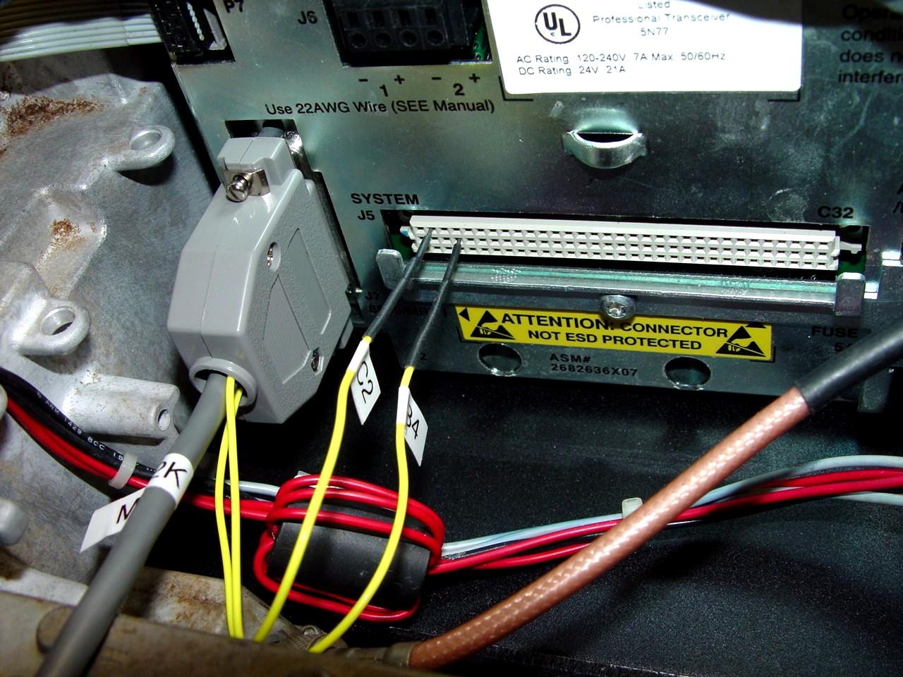
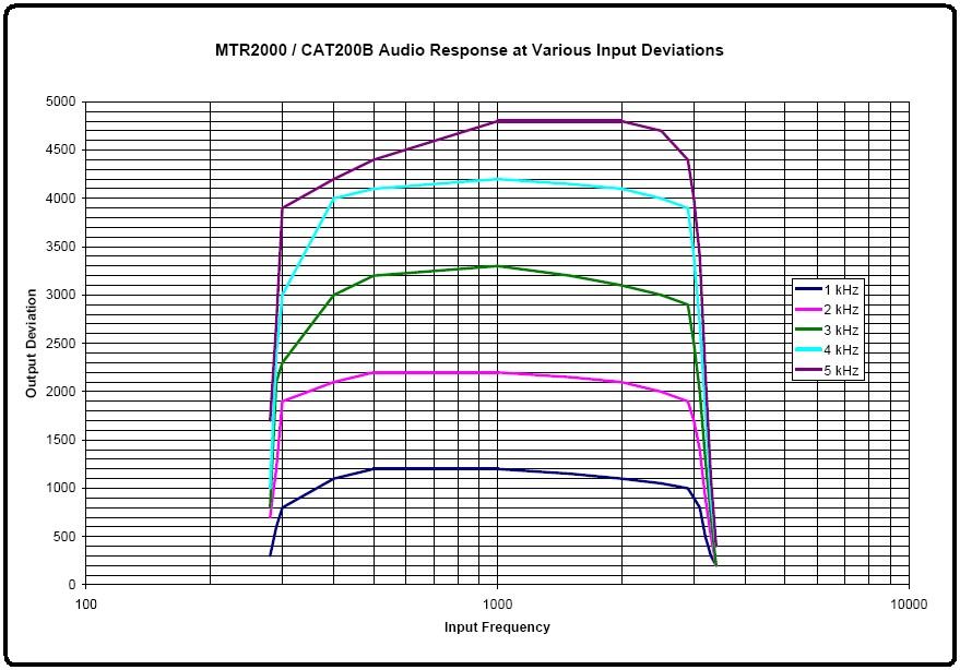
Basically it all worked great the first time I tried it. I heard the CAT200B sign-on message come out of my portable radio, and I could key up the repeater. Listening to another receiver told me I had way too much receive audio, but a couple of adjustments on the CAT200B controller took care of that. In fact, the audio is basically running with perfect settings: 1 kHz of input deviation produces 1 kHz of output deviation, up until things start limiting at over 4 kHz of input deviation. The graph below shows the output deviation at various input deviation levels, over the usable frequency range.
I discovered that the MTR2000 is quite unhappy if any of the MRTI input lines are grounded when the station is powering up or recovering from a reset, which happens every time the code plug is written out to the station. It just gets caught in a repeating reset loop until the grounded lines are removed, then it recovers nicely. Apparently this is a known "feature" of these stations, but it seems to me Motorola could have done a better job of things and accommodated such conditions. I'm using the CAT200B's switched output #1 to ground the MRTI Monitor signal, which puts the receiver into carrier squelch mode when that signal is active. If you leave it that way and the station reboots, it'll get caught in this reset loop. There is an internal Reset signal but it's not brought out to the user connectors. If there was, I'd use it to trigger a relay to disconnect the PTT and Monitor signals for a couple of minutes when the station boots up.
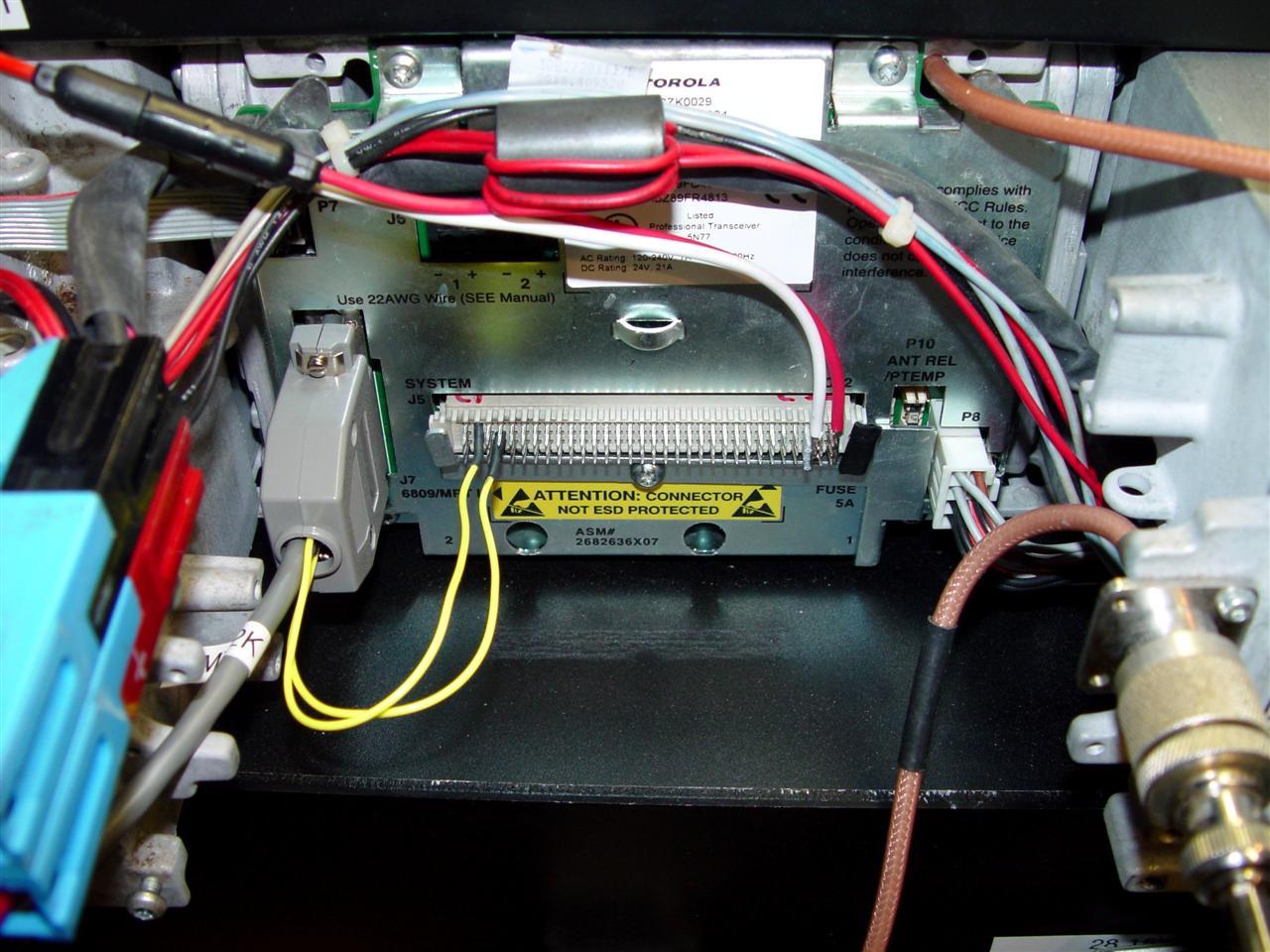
I eventually wired up the system connector. I attached power wires for the CAT200B controller to pins A31/B31/C31 (Ground) and A32/B32/C32 (+14.1VDC); these are the red and white wires at the right end of the connector. I also put some teflon sleeving over the A30/B30/C30 pins to prevent the ground wire from shorting them out. The B4 and C2 wires went directly to their respective pins. I added some insulating tape to the right-hand tab of the the connector hold-down bracket because it was too close to the +14.1VDC wire for comfort. The connector is a very tight fit, primarily because all 96 pins are making contact.
Contact Information:
The author can be contacted at: his-callsign [ at ] comcast [ dot ] net.
Back to the top of the page
Up one level (MTR2000 Index)
Up two levels (Main Moto Index)
Back to Home
This page originally posted on 29-Oct-2012
Article text, photos, and hand-coded HTML © Copyright 2012 by Robert W. Meister WA1MIK.
This web page, this web site, the information presented in and on its pages and in these modifications and conversions is © Copyrighted 1995 and (date of last update) by Kevin Custer W3KKC and multiple originating authors. All Rights Reserved, including that of paper and web publication elsewhere.