Motorola index
Back to Home
R100 EEPROMs
By Robert W. Meister WA1MIK
With Input From Bernard Barink AJ4SX

|
R100 index Motorola index Back to Home |
Replacing the R100 EEPROMs By Robert W. Meister WA1MIK With Input From Bernard Barink AJ4SX |
|
Background:
The UHF R100 stations use two separate radios, each with just enough components to perform the function (transmitter or receiver). This allows full-duplex operation. The radios were built for either Private Line (PL) or Digital Private Line (DPL), and a different microprocessor was programmed and provided to switch between these two coded squelch systems. Motorola no longer supports these stations nor do they have any parts for them, so you're stuck with whatever you've got (PL or DPL).
The EEPROMs used in these stations to retain the code plug information (a PCD8572) may go bad after a long time (10 years), too many write cycles (10,000), or by using a programming computer that's too fast for the job. This is what happened to Bernard: his computer wasn't too fast to read the EEPROM, but it was too fast to write it, and he ended up with a bad checksum in the EEPROM and no way to read it or fix it with the available software. He sent me an e-mail asking for help and the experimenting began.
Not All Serial EEPROMs Are The Same:
The code plug data is stored in a 1024-bit (128 byte) serial EEPROM. They're called serial because the data is transferred on one dedicated line in a serial fashion. A clock signal toggles the data and the protocol follows the I2C standard. As the PCD8572 chip is no longer available, we started looking for suitable replacements. The 85C72 was initially thought to be a good substitute, but we eventually concluded that the 24C01-series of serial EEPROMs should work. They all had identical specs and pin-outs, although pin 7 had a different function depending on the manufacturer and the part number. See the various data sheets below. These can be bought from most large parts suppliers like Mouser and Digikey for about $0.40US each. We know the AT24C01B works and the AT24C01C programs just fine, although I haven't tried one in an R100 yet.
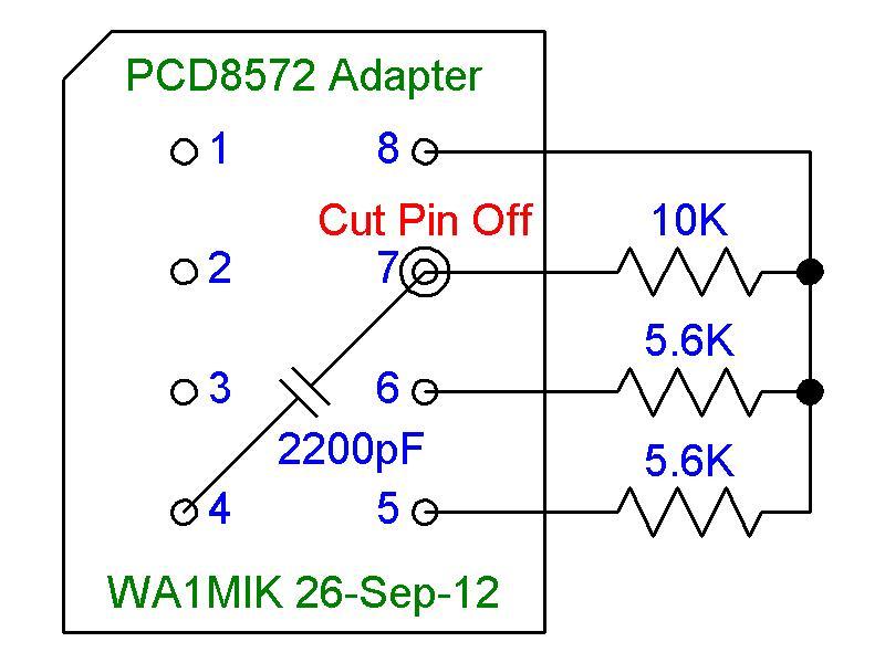
I decided to try reading the data from the chip with my EPROM burner that claims to be capable of handling many serial EEPROMs. I selected a generic 24C01 serial EEPROM, inserted the R100's chip into my EPROM burner, and attempted to read it, but I didn't get valid data. In desperation I added the RC network components present in the radio on pin 7 to an IC socket, inserted my EEPROM into it, and plugged that into the EPROM burner. I still was unable to read the data. I attached my oscilloscope to the serial clock (SCL) and serial data (SDA) pins of the chip and tried reading it again. I could see short bursts of data but nothing that looked like 128 bytes-worth. As I concentrated on the scope display, I failed to notice that the EPROM burner software had apparently successfully read the data from the chip. I think the scope probes loaded the SCL and SCA data lines just enough to make things work. As a substitute, I added 5.6k pull-up resistors to those two data lines and was able to read the chips just fine. I made an adapter using half of a 16-pin wire-wrap IC socket and a few other parts to simulate the circuit in the R100 radio. This adapter is only necessary to read the original PCD8572 chip. Note that the wire-wrap pin that accepts the EEPROM's pin 7, has been cut short, so it won't be seen by the EPROM programmer. The schematic diagram is shown below.
I saved the data to a file, repeated the process with the other EEPROM, and finally had something to work with. I sent these two files to Bernard who was able to utilize them to successfully get his station working again by writing the data to an AT24C01B chip and installing that into his system. In the process, he documented the various bytes in the EEPROM. Through additional experimentation and memory examination, we have both refined that information and it is available as a separate article available in the R100 area of this web site.
Taking The Easy Way Out:
Lest you think you can just read the existing code plug from the PCD8572, turn off the station, stuff in a new blank 24C01 chip, power the station back up, and write the code plug data to it, this won't work. The software apparently checks that you haven't done that and verifies the serial number and other data in the chip in the radio before writing to it, and unless you've pre-programmed enough data for it to pass muster, it won't work that way. You can't just install a factory-erased (blank) chip because it needs to have some amount of data in it to be recognized and accepted by the radio and the programming software. The data layout is slightly different for the two chips, and of course you can't change between PL and DPL just by changing the programming. So your best bet is to program the new chip properly in an external EPROM burner so it can be installed into the station. Once it's in and working, you can use the normal programming software to modify the code plug as needed.
Motorola's RSS verifies the checksum, among other things, in any EEPROM it reads. A failure to pass muster means you get nothing to work with. It may be possible to create a new code plug in memory with the lab version, and write it to the station, but again, RSS reads the EEPROM first and if that fails for any reason, you still can't write a good code plug to the station. You're effectively blocked from resolving the problem with the Motorola software.
I have gotten around this problem by writing my own program that will write a code plug file to the radio without having to read anything from the radio first. (Of course, this means I needed a program to create a good code plug file in the first place.) It will also read a code plug file and save that to disk for archiving or later analysis. Motorola just went overboard with all the checks and balances they put into their program. And before you ask, I will no longer give out or sell these programs.
Hardware Incompatibilities:
There is one hardware issue that you need to deal with, and that's pin 7 on the EEPROM. The radio and the PCD8572 have a timing network on that pin that's not needed by the newer chips. All of the current chips treat this pin differently. Some devices (those made by Microchip) ignore pin 7 and their data sheets say it can be tied high, tied low, or left floating. Other devices require pin 7 to be grounded or not connected to allow writing, in other words it's a write-protect pin when pulled high. The parts on the R100 radios will pull pin 7 high, inhibiting writing of these chips, unless you do something about it.
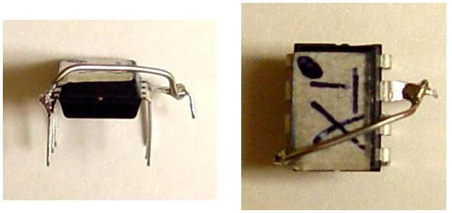
There are two easy ways to deal with this: you can bend pin 7 of the chip up and out of the way, then solder a small jumper from the raised pin 7 over to pin 4 (ground). This will allow the station and any external EPROM burner set for any manufacturer's 24C01 IC to write to the chip. Another way is to apply the ground signal at the IC socket on the R100 radios, by grounding one end of JU706, which is a cut jumper near the IC socket. This will allow the station to write to the chip when it's inserted in that socket, but your EPROM burner will then need to ground that pin when it writes to it, so you'd have to select the proper device manufacturer and part number. It seems far easier to add the wire directly to the IC as it's out in the open and very accessible, and this is what I did.
Rather than worry about whether a particular chip uses pin 7, I just add the ground wire (shown below) before using it in my external EEPROM programmer or the R100.
Initializing The New EEPROM:
Once you've got a programming environment set up, you can enter the appropriate data into your EPROM programmer, write to the serial EEPROM, insert it into the station, and fine-tune any settings if necessary. It makes sense to enter as little as possible so you can get the new chip working in the station, then use the regular R100 software to make the final settings. For example, set the frequency to 460.00000 MHz, no PL/DPL, and no timeout. As long as the constant data, checksum, and a few other bytes are correct (for example, you can't tell the code plug to do DPL if the radios can only do PL), the new chip should be accepted and you can reprogram it as needed with the R100 programming software.
There is a "memory" mode available in the R100 software that will let you view and enter any value at any location. You can use this to examine what's been read from a station, or to examine what you're about to write to the station. After making some hex-edits of the software, you also gain the ability to create a brand new code plug image for either the transmitter or the receiver. You can examine and write the data on paper, then enter those bytes into your EPROM burner and write a new chip. You will have to recalculate the checksum; we leave that as an exercise for the student (I always hated to see that in textbooks).
The Results:
Using the pre-programmed chips that Bernard sent me, I grounded pin 7 at the chip by bending the lead out of the way and soldering a piece of hookup wire from pin 7 to pin 4. I plugged the ICs into the station and it seemed to work just fine. I then attached a programming cable and tried modifying the code plug data, just to make sure it could be read and written. Both EEPROMs were read, modified, written, tested, read, put back to their original values, written, and tested again, so I'd say the transplant was successful. Here is a photo showing how the jumper was added to the chip.
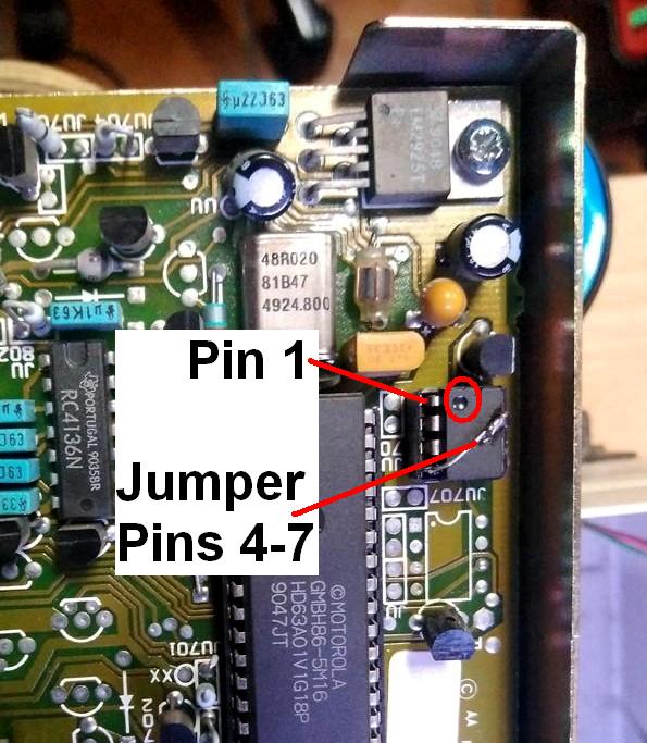
Here's a photo (courtesy of Javier EB1WB) of one of these chips installed in a receive radio next to the microprocessor. Note the orientation and location of pin 1 (the dot) and the jumper. The transmit radio has an identical chip installed.
I don't know if I can do anything with original EEPROMs that may have gone bad or have a bad checksum. I can create two new code plug EEPROMs if you provide all the necessary data (frequencies, PL or DPL radio types, PL or DPL codes or CSQ, transmit time-out value). Contact me via e-mail for further information. I've had great luck with Digikey p/n 24C01C/P-ND; these are Microchip Technology (MTI) parts and they ignore pin 7 but I add the ground wire anyway.
Datasheets:
Several datasheets are available on the web. I've collected a few here.
A PCD8572 datasheet can be found here.
A Microchip 85C72 datasheet can be found here.
An ST-Micro M24C01 datasheet can be found here.
An Atmel AT24C01B datasheet can be found here.
A Microchip 24LC01B datasheet can be found here.
A Microchip 24C01C datasheet can be found here.
Home-grown Programs:
After getting a few requests to program new EEPROMs or come up with the proper file to burn into a new EEPROM, I wrote a program in September 2012 to create two code plug image files that can be used to program 24C01 serial EEPROMs. It asks all the questions for both the receiver and transmitter, verifies the data then writes out two binary image files that can be used by an EEPROM burner or some other program.
In May 2013 I wrote another program that can read and write the radio's code plug files and can load them from, or save them to, disk files. Together with the above program, I now have the ability to insert blank EEPROMs into the radio and program them from scratch, and maintain these code plug files just like any other RSS package. Computer speed doesn't seem to be an issue; this program ran perfectly fine on a 3.5 GHz Pentium IV computer running Windows XP.
Neither of these programs are available to anyone else, so don't even ask!
Acknowledgements and Credits:
Bernard AJ4SX gave me the initial shove to work on this article. He was kind enough to send me two pre-programmed AT24C01B chips to play with. They are now working fine in my station.
Radius R100, PL, and DPL are trademarks of Motorola, Inc.
Other trademarks are those of their respective manufacturer.
Contact Information:
Bob can be contacted at: his-callsign [ at ] comcast [ dot ] net.
Back to the top of the page
Up one level (R100 index)
Up two levels (Motorola index)
Back to Home
This page originally posted on Tuesday 26-Sep-2012
Article text, artistic layout, photographs, and hand-coded HTML © Copyright 2012 by Robert W. Meister WA1MIK.
This web page, this web site, the information presented in and on its pages and in these modifications and conversions is © Copyrighted 1995 and (date of last update) by Kevin Custer W3KKC and multiple originating authors. All Rights Reserved, including that of paper and web publication elsewhere.