Back to Home
Micor Receiver with
a MaxTrac Radio
By Anthony Stump KE4KQI

|
Up one level Back to Home |
Replacing a Spectra TAC Micor Receiver with a MaxTrac Radio By Anthony Stump KE4KQI |
|
Background:
With the closing of International Crystal Manufacturing (ICM), there are limited sources to economically re-crystal channel elements for hams. Not that it was economical to begin with. You have to be 100% sure of your operating frequency when you order or you could be out $60 or more. When operating control links, it's possible you may need to change the frequency at some point due to interference.
The Spectra TAC receiver is a wonderful piece of hardware. It was designed to work with the Spectra TAC comparator both locally and via phone line. The internals are quite simple, a Micor receiver connected to a modular shelf with an audio control card, tone generator, and PL decoder. The Micor receiver board itself only has four lines to the board: +13.8v, +9.6v, ground, and discriminator out. So let's make it synthesized!
Ok, this is not an original idea at all; many have converted a Micor to synthesized operation by swapping the internals using different items such as a modified channel element, a portable radio, even 3rd party oscillators have been used in large trunking systems where simulcasting is taking place. I have also seen other articles where mobile radios where used with the shelf externally. Why not put the radio IN the Spectra TAC chassis and keep the classic look?
There are many ways to do this, I am going to cover one crude way, but you may know or think of better ways. This may not be practical for your application, especially if you have a large number of RF links. My construction on this round was not the "best" nor was it using desirable methods of engineering and construction. Since it was more of a "prototype" and I wasn't even sure it would work appropriately, I promise my next will be better. Before we get started, let's go over the pros and cons to this conversion.
| PROS | CONS |
|---|---|
| Self contained | Tough to work on if radio goes bad |
| Classic look | Static sensitive components |
| Good frequency response | Voting COULD be affected |
| Good RX sensitivity | External RF Interference could be an issue |
| Clean audio when tuned properly | |
| Cheap to replace | |
| Easy to change frequencies if needed |
Looks like the PROs out weigh the CONS; let's get started!
Construction:
Let's get started by prepping the MaxTrac. You don't really have to use a MaxTrac; a Radius M208, M120, GM300, or other variant will do. The SM120 and M1225,even though smaller in size just would not fit into the chassis due to the volume control and antenna connector; these kinds of radios work better exterior to the shelves and are very inexpensive! Just make sure your MaxTrac has a 16-pin accessory connector and provides un-muted, unfiltered audio or you will need to construct an op-amp circuit to amplify audio on pin 3 of J6, the internal connection between the RF Board and the Logic Board. Other radio makes and models may work as well, you never know until you try.
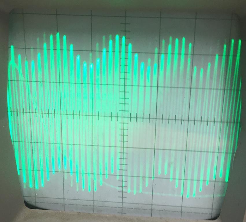
The photo above represents the output audio of pin 3 on J6. It's considerably lower than the audio from pin 11 on the accessory connector. The photo below photo is the audio from this pin, un-muted and not de-emphasized.
A MaxTrac is recommended due to the construction of the front panel connections, and because of wider operating band splits. Make sure the MaxTrac is fully functional before doing this conversion. Program your desired link frequency; make sure the VCO locks and you can receive at full specifications. Motorola specifies around 0.25uv for 12dB SINAD.
After you verify the radio is fully functional on receive, you can start the conversion. Remove the covers, front and PA heat sink. Remove the RF Board shield. Set the JU551 jumper on the Logic Board to FLAT UN-MUTED AUDIO position A.
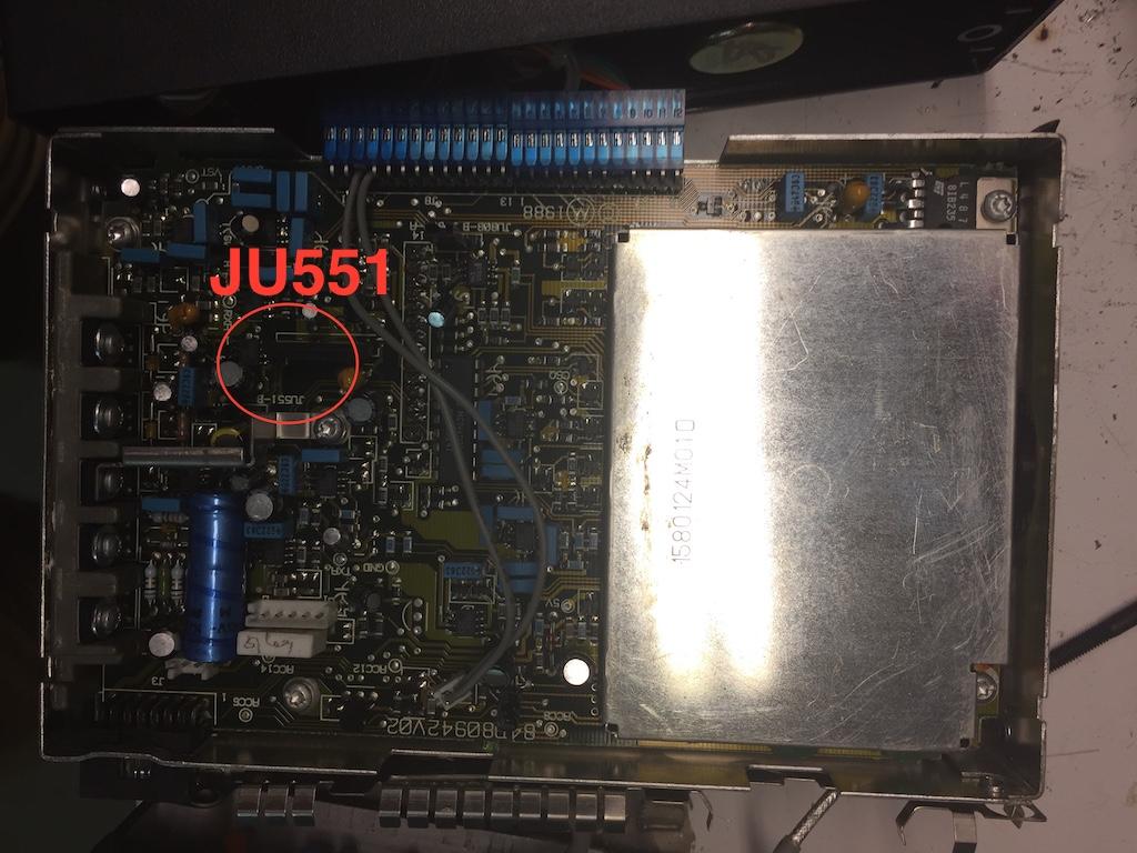
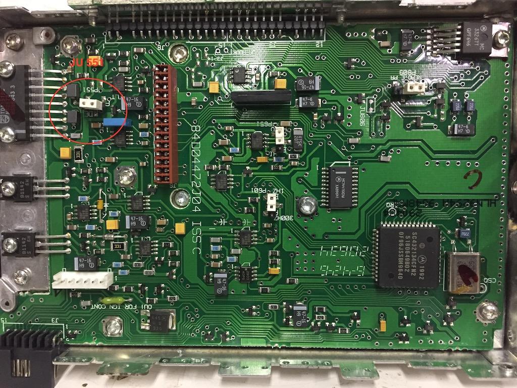
The photos above show the location of JU551 on each variation of logic board. Note that the lower photo is actually a GM300 logic board.
Set the squelch pot on the RF board all the way counter-clockwise to fully open the squelch. Since we are not muting the audio, this is not very important but I do it anyway. Your main squelch control will be on your audio control module anyway. You can also remove the capacitor to improve the receiver response time if you are using the internal squelch and not the stock PL decoder card. These are completely optional.
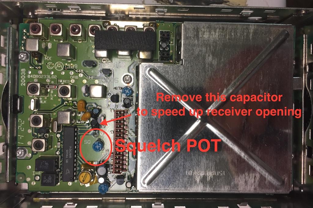
The photo above shows the locations on the RF Board of components that you may want to change.
Completely remove the PA heat sink assembly. Carefully remove one of the crimp connectors form the cables going to the RF Board. Most of the time, you can simply pull it off with a pair of pliers. Set this in a safe place, you will need it later. If you prefer, you can unsolder the entire jumper from the PA and place an RCA style RF connector on the end instead of cutting the Spectra TAC cable. If you plan on using the Micor preselector, you would want to do this and save the RCA connector. The MaxTrac cable can be soldered onto the preselector. Since our site is not that busy, I did not explore this option but may in the future.

The RF connector on the MaxTrac style radio you will remove and save.
With the radio completely disassembled, it's time to wire. Solder a wire jumper from the fuse on the Logic Board on the end that comes from the PA deck; this is your positive. Solder another wire to pin 11 of the 16-pin accessory connector. Forget about using the plug, there just isn't enough room. You can also run a line to a pre-programmed pin for PL detect and/or COS if you like. This line will go to the audio control card and will require a buffer circuit and some jumper changes on the audio control cards. I am using the stock PL card and reed for nostalgic purposes and to keep it simple... for now.
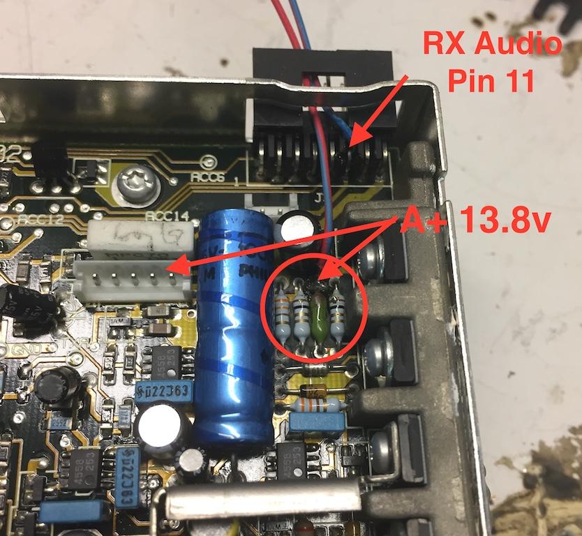
The above photo shows connection points on the Logic Board for audio and power. Ground can be provided through the chassis but if you prefer, you can run a ground wire from any grounding point on the MaxTrac to the Spectra TAC interconnect board; just never use pin 1 on your accessory connector.
Now it's time to prepare the Spectra TAC. Make sure it works before this conversion; at least the power supply and the card shelf. Remove the front cover and pull out the shield. Take out the Micor receiver board and set it aside, use it as a spare, sell it, or keep it in case you want to revert back.

The photo above is the Micor board you will remove.
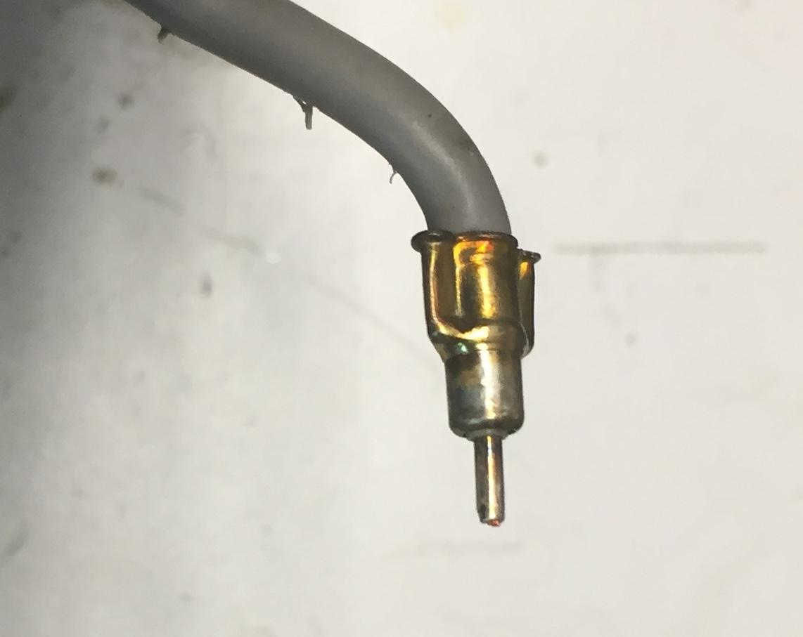
Next step is to cut off the old RF connector and prep it to take the smaller MaxTrac connector. If you are planning on using the Micor pre-selector, skip this step. Remove about 1/4 inch of the center conductor insulation. Next, strip off another 1/4 inch of the braid shield insulation. Solder the center conductor to make a solid pin-type connector. Slip the MaxTrac crimp connector over the center pin and down to the braided shield. Do not worry about getting the braid under the crimp. Trim off the excess braid and solder to the crimp; make sure the connector is not shorted before and after soldering. You may prefer to remove the entire coax from the MaxTrac PA and fabricate an adaptor; it's your preference. I can say that the method I used proved to show no added loss in receive sensitivity and showed no signs of bad connections when tested. Due to the stiffness of the coax, I did have to tie-wrap it to the MaxTrac chassis for stability.

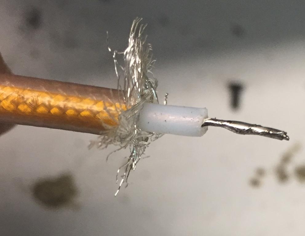
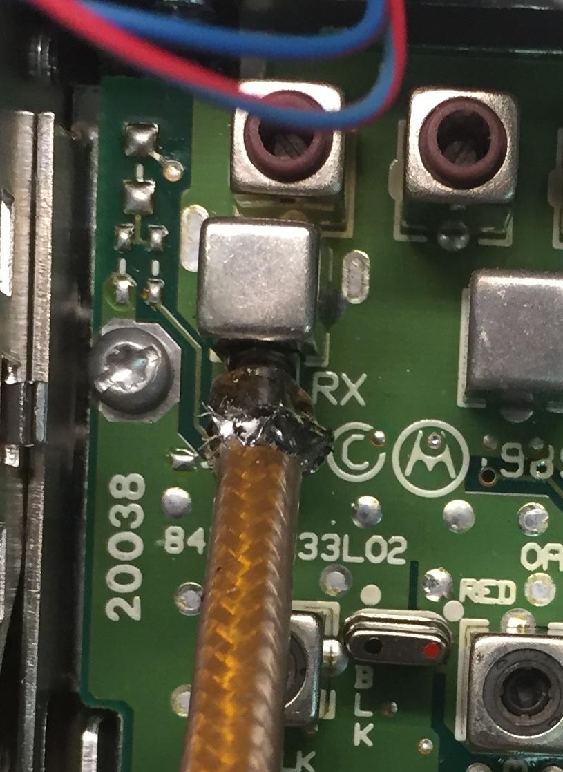
The above photos show the coax stripped and the center pin soldered, ready for the MaxTrac RX connector.
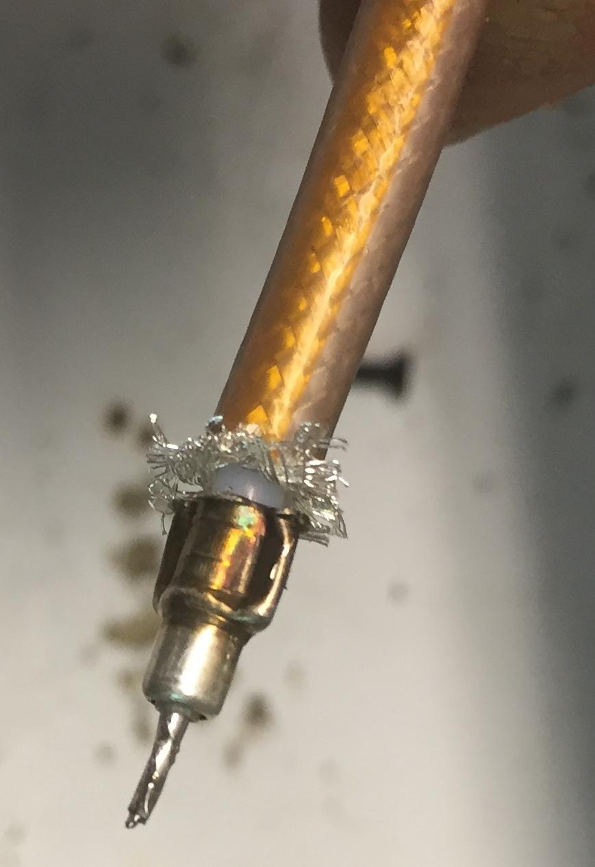
Slide the small connector over the center pin and drape some of the braid over the crimp end, then solder the braid to the crimp.
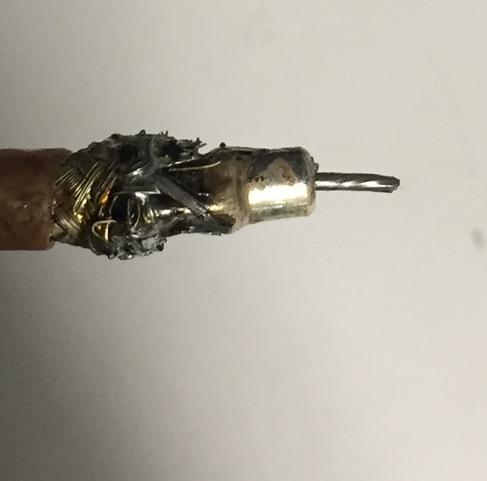
The photo above shows the finished connector.
With the RF connector now ready, measure and drill two holes in the bottom of the Spectra TAC chassis that will line up with the front cover screw holes on the MaxTrac. If you are using a GM300 style, you will turn the radio upside down therefore you should drill the holes to match the PA heat sink mounting holes. Bend the front panel pins J8 and J9 UPWARD on the MaxTrac so they will be out of the way in the chassis. This is another reason I prefer the MaxTrac to the GM300, since the GM300 and other similar models have the front panel pins mounted on a board that mounts to the chassis.
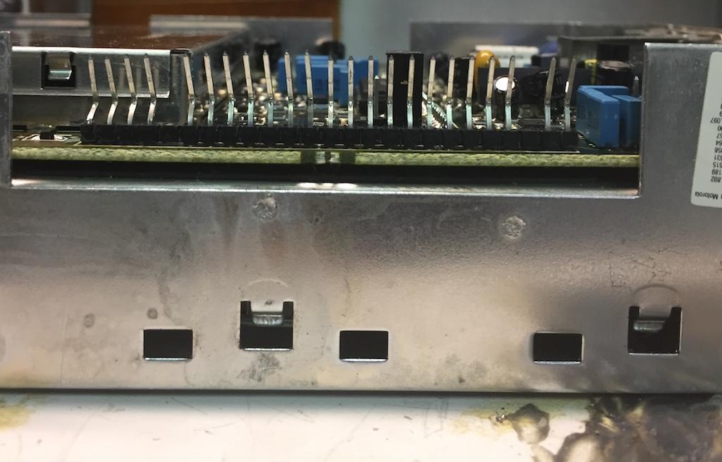
The photo above shows how the pins on J8 and J9 (front panel connectors) are bent upwards on the MaxTrac, to keep them from shorting out on the Spectra TAC chassis.
Connect the Volume Control/Mike connector to the MaxTrac J8 after removing that assembly from the front housing. You may want to jumper the power switch on the Volume Board or the Logic Board connection point so that the radio is on all the time and can't be accidentally turned off. Connect the MaxTrac power and audio wires to the interconnect board on the Spectra TAC. You can solder or use Micor pins in case you ever need to remove it for service. You don't need the front panel Display and Button board or its connections. You will need to program the radio for only one mode.

The photo above shows the front panel connections necessary for programming.

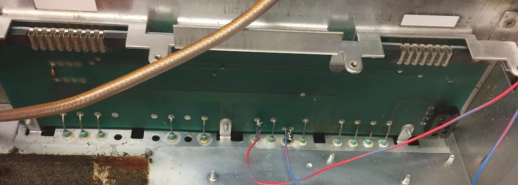
The photos above show the connection points in the Spectra TAC on the interconnect board. Even though the chassis provides a ground for the radio, it is good construction practice to wire bond a ground point on the interconnect board to a ground point on the MaxTrac. Just do not use pin 1 on the 16-pin connector!
Bend the two screw mounting tabs in the bottom front of the Spectra TAC chassis down, then slide in the MaxTrac. Point the RF board out to the front since this is the one where you would make adjustments and connect the RX cable. The Front Panel connector should be facing down. Put a spacer such as a metal washer between the Spectra TAC chassis and the MaxTrac, making sure it's thick enough to keep from pinching the wires. Use the PA mounting screws to mount the MaxTrac; you will need to trim these down with a rotary tool or cutters. By the way, these radios use Metric hardware.
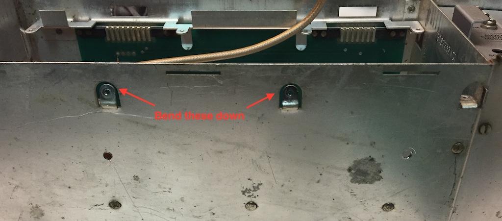
This photo shows the bent screw tabs on the Spectra TAC chassis.

This photo shows how the PA bolts were cut for mounting the MaxTrac.
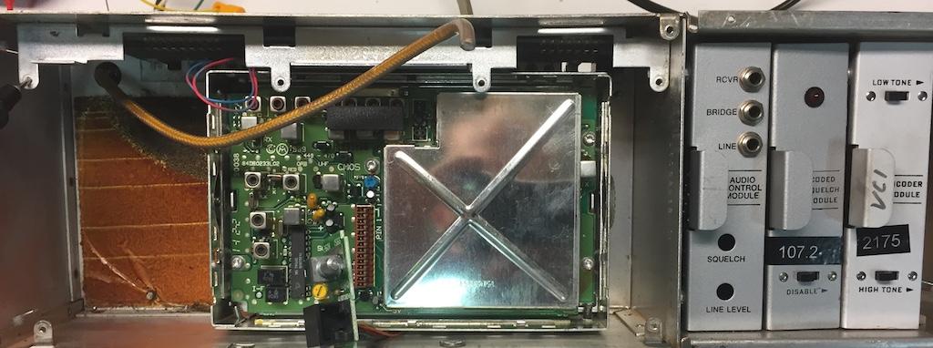
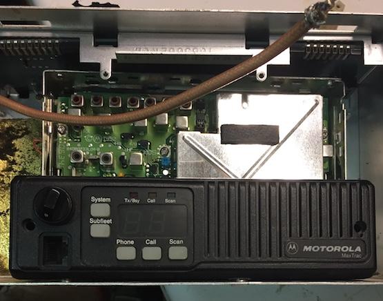
This is the finished product: a MaxTrac mounted in the Spectra TAC chassis.
Now that the MaxTrac is wired and mounted, connect the receive antenna cable to the unit's RX port. I glued the programming port to the VCO shield and put a label on the shield indicating what kind of radio it was for RSS purposes. In a perfect world, they all should be the same. Since I have a pile of old UHF radios (some with bad PAs) of different varieties it was more cost effective to use what I had. This worked out because I was able to test three variations and find the one that worked the best, which was a MaxTrac, hands down. Another idea is to run a cat5 network cable out of the back of the chassis and connect the wires to a junction or bulkhead connector for programming in one central location. Do not worry about replacing the MaxTrac RF Board main shield or the Micor shield; so far the front cover of the Spectra TAC is providing enough RF shielding.
The photo above shows the receive antenna cable hooked to the MaxTrac. You may want to secure it with a tie-wrap to prevent it from coming out.
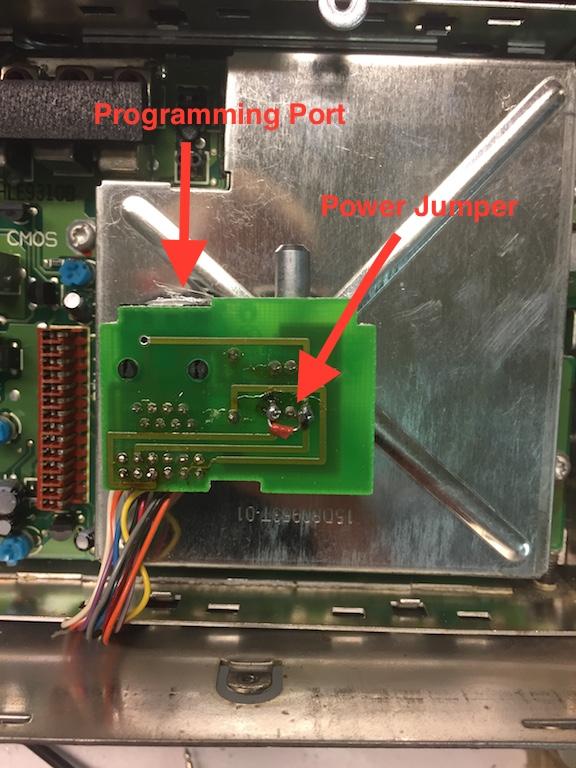
The photo above shows the programming connector for future programming.

It's a good idea to label the connector with the radio's model number for future service needs, especially if you used several different types of radios, as they could use different RSS packages for programming.

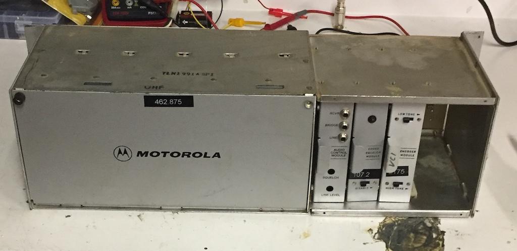
The above photo shows three shelves converted; the top is still a stock Micor that I will use for comparison testing, described in the below section. The reason the bottom radio is so far to the left is because it was an M120 that had to be flipped over due to the front panel connectors. It is possible to just remove the pins, but I wanted to keep them just in case I ever needed them for service purposes.
Testing:
Now that the conversion is completed, I wanted to run a few test and compare with a stock Micor. Bob, WA1MIK gave me a few ideas on what to test. I programmed up one of the new Spectra TAC shelves for the same frequency as the stock Micor shelf. I made sure the Micor receiver was aligned to the best of its ability and tested the receive sensitivity of both. The MaxTrac was way more sensitive. Due to its age, the Micor shelf receiver was very poor in comparison. The Micor was about 0.8 uV for 12dB SINAD and the MaxTrac was 0.25 uV. To make sure we were on a level playing field, I did a complete shelf alignment of the levels going to the comparator shelf with my transmission line test set. I put a small attenuator on the MaxTrac's antenna input to even it out with the Micor. When an RF signal was injected into the combiner, both units voted equally and switched as levels were adjusted. Next, I did a frequency response test by injecting a signal at a full quieting level.
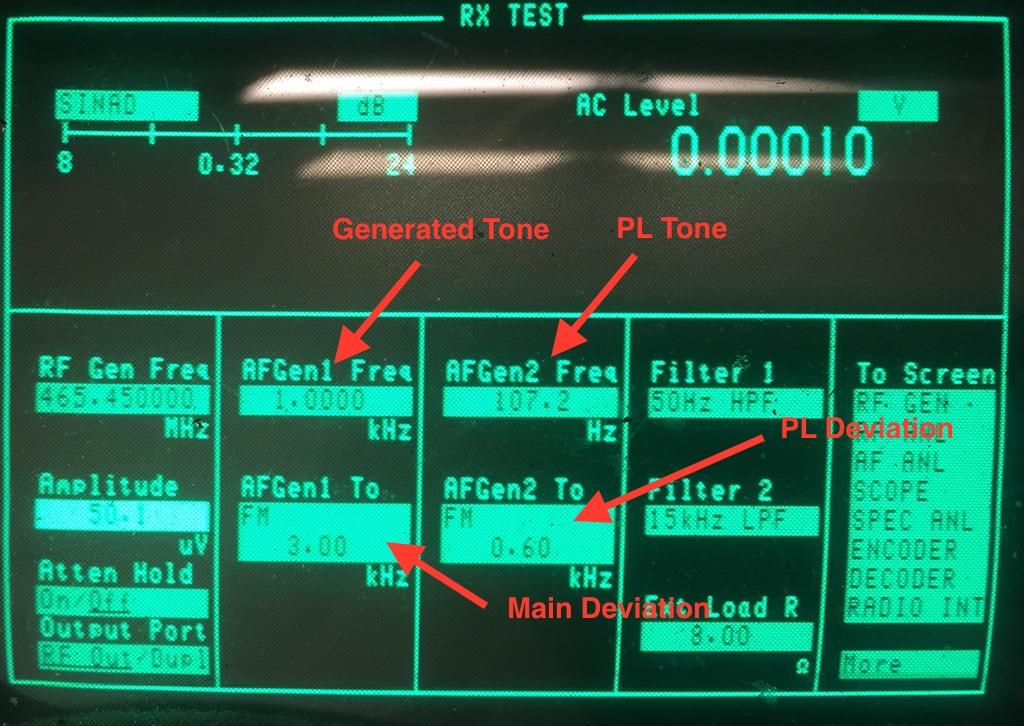
The photo above shows the equipment setup used for the frequency response test.
I started at 200 Hz and increased the frequency in 10 Hz steps and recorded the levels of each receiver. I used the bridge port on the front of the audio control card because it was easy and convenient, keeping in mind that the bridge port shows up 3dB hotter than the termination point at the SQM. Both shelves opened up at 240 Hz. As the tone frequency increased, the levels on both shelves stayed relatively the same. Both units started failing the comparator SQMs after one minute of injected tone at 1700 Hz (close to status tone). When the status tone frequency was reached, both units cleared the SQMs on the comparator. This continued up to about 3300 Hz. Levels dropped to -30dBm at around 6300 Hz on the Micor and 7600 Hz on the MaxTrac. To rule out any variables, cards were swapped between the shelves and tests were run again with close to the same results. The levels stayed pretty close to each other but the trend also followed the cards, as expected. The only real disadvantage to the Micor, besides crystals, was the receive sensitivity, which I am not going to rule out as bad hardware. The MaxTrac seems to be more than a satisfactory replacement.

In the photo above, the blue trace is the Micor and the green trace is the MaxTrac.

The photo above shows the frequency response after swapping the cards. The winning levels in the first test followed the cards, but in all, the levels at each frequency stayed close to each other. I measured the audio levels of both units prior to conversion. The Micor audio level was around 1.5 Vpp when injected with a 1 kHz tone at 3 kHz deviation. The MaxTrac was about 1.2 to 1.4 Vpp, however, a Radius mobile was a bit lower at 1.1 Vpp; not enough to make much difference. I have heard that some MaxTrac receive levels are lower than others.
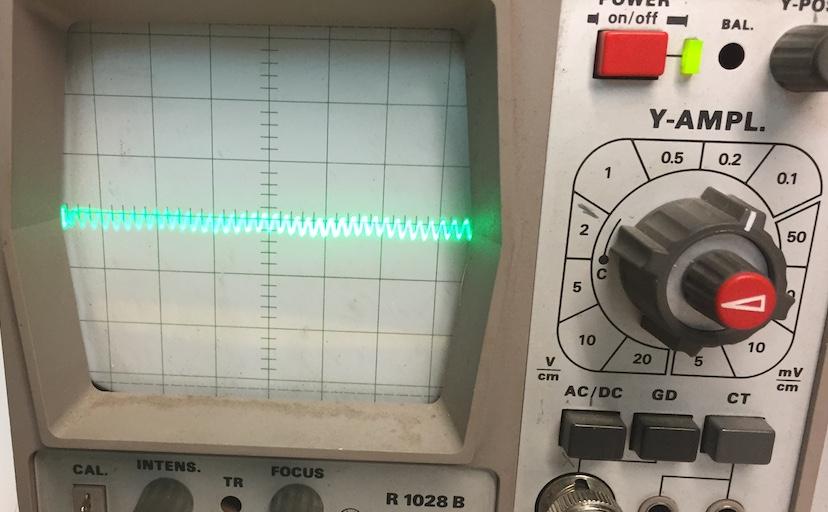
The photo above is the measurement of the audio output of the MaxTrac at pin 11 of the accessory connector, measured at 0.2v per division on the oscilloscope.

The photo above is the measurement of the audio output of the Micor, measured at 0.5v per division on the oscilloscope.
In conclusion, the MaxTrac was a suitable replacement for the stock Micor receiver in the Spectra TAC shelf. The receiver performed excellent, even using a 4:1 RF splitter with no pre-amp. The frequency response curve of the unit followed the stock Micor very closely. In the voting test the MaxTrac was selected properly and handed off to the Micor when its signal was attenuated into the lower level or a fade condition. Another test was planned using an actual RF link setup, but this didn't take place due to time constrains and having to clean up the shop to make room for another project.
MaxTrac Programming Tips:
On the Radio-wide page (F2), make sure "Off-Hook PL" is YES, otherwise if you are using the MaxTrac PL, you will need a shorting plug.

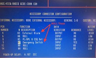
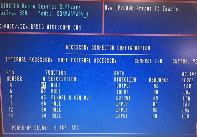
On the Accessory Connector page (F9), NULL out all input and outputs except for a PL/CSQ output that you can use if you desire not to use the stock Spectra TAC card. If you use this option, you will need a buffer circuit to convert the MaxTrac low to 13.8v on PL or if you prefer high, you will need a buffer circuit to convert the 5v high to 13.8v.
On the Mode page (F5), while depressing SHIFT (for out-of-band), enter the frequency of your receiver. Enter "B" or all spaces for the transmit frequency to blank it out.

Use the "SHIFT" method for entering frequencies out-of-band limits of the MaxTrac. Fill in all characters and hold shift for every number except the decimal point. Be sure the radio functions properly on any "out-of-band" frequency as some have been known to go out of lock. A slight VCO adjustment is usually all that's required.
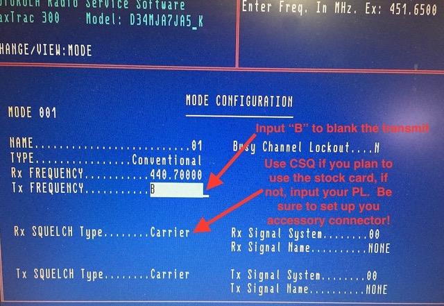
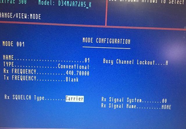
If you are going to use the MaxTrac PL decoder and not the Spectra TAC card, enter your PL here, otherwise use Carrier Squelch (CSQ).
Maintenance Provisions:
I left the MaxTrac control head on in my last conversion, but the volume control proved to extend too far out and would need modification to allow the front cover to be used. There are several ways this could be dealt with: put in a different potentiometer without the knob or move the stock potentiometer to a different location. Since I didn't really want to use either of these options, I decided to use the Spectra TAC metering card. This card, even though it didn't work correctly, has a good audio amplifier and speaker and I didn't want it to go to waste or have to be moved form shelf to shelf when I needed to service the receivers.
Someone put a trunking faceplate on a UHF conventional radio.
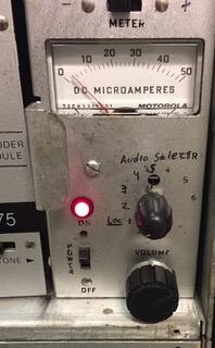
The photo above is the test card that came in one of my shelves. The meter is inoperable and other than the audio section, it pretty useless. Since the MaxTracs don't have a control head, I put it to better use to monitor the receiver audio signals.
I modified the test card and the backplane so that the meter selector switch now switches between receivers. This is a simple modification, just jumper the audio input at pin 18 to the switch's position 1. To do this, separate pin 18 from the audio section input by removing JU1 and R1. Run a wire from the pin 18 side of J1 to switch position 1 and the other side to the common on the switch (input to audio section). Pins 2, 3 and 4 will go to switch positions 2, 3, and 4 (you may need to move some wires). I took the advice of Bob, WA1MIK, and replaced the potentiometer on the front of the service module to give a more "useable" volume control with a new knob.
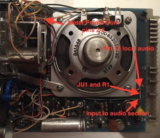
The photo above shows the modifications needed to change the meter switch so it monitors shelf audio.
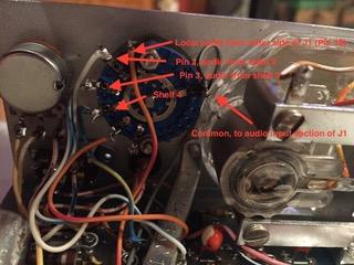
Here's the modification to the meter switch. Sorry for the dark contrast; I could not get the light just right, but it gives you a general idea of the simplicity of this modification.
On the back of shelf 1, run a wire from pin 2 to shelf 2's pin 18 then run a wire from pin 3 to shelf 3's pin 18. Finally, connect pin 4 of shelf 1 to shelf 4's pin 18. I cut the traces on shelf 1 going to the meter connections, but since you're not using the meter port, this was not really necessary, as they aren't connected to anything else. The meter in shelf 1 can now monitor the audio from any receiver.
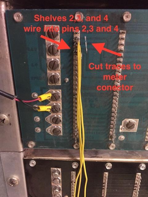
The photo above shows the backplane connection point on shelf 1, or whichever shelf will house your service module. The cut traces were not necessary.
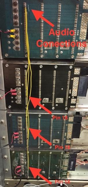
Here's a photo showing the wires added to the backplane, pin 2 going to shelf 2, pin 18 and so on.
Acknowledgements and Credits:
Spectra TAC, MaxTrac, Micor, M120, GP300, and Radius are trademarks of Motorola, Inc.
Jumper settings and wiring came from respective service manuals.
Special thanks to Robert Meister, WA1MIK for extra information.
Contact Information:
The author can be contacted at: stump_andy [at] yahoo [dot] com.
Back to the top of the page
Up one level
Back to Home
This page originally composed on Saturday 20-May-2017.
Photographs, article text, and layout © Copyright 2017 by Anthony Stump KE4KQI. All photographs were taken by the author.
This web page, this web site, the information presented in and on its pages and in these modifications and conversions is © Copyrighted 1995 and (date of last update) by Kevin Custer W3KKC and multiple originating authors. All Rights Reserved, including that of paper and web publication elsewhere.