Back to Home
with RF Links and MSF5000
By Anthony Stump KE4KQI

|
Up one level Back to Home |
Simple Spectra TAC Hookup with RF Links and MSF5000 By Anthony Stump KE4KQI |
|
The idea was brought up to put multiple voting receivers around the county for our UHF repeater that is linked to the statewide MTEARS (mtears.org) network to expand our coverage. We are running a MSF5000 UHF CXB station with a possibility of 2 or 3 remote receivers. But first, a little bit of a story.
A Little Story:
About a year ago out of impulse, I bid on a Spectra TAC comparator on eBay for about $30 and won it. It included three signal quality modules (SQM), and the command module. Not knowing at the time what I would even do with it, I shelved it... just in case.
Fast-forward a year; upgrades to my repeater network were needed. I asked for donations and got enough money to get started on adding and replacing equipment to improve our groups network on our 2m and link the UHF network to MTEARS. A fellow ham we know has a warehouse full of old radio equipment that he removes from sites for a tower company and sells it to other hams and on eBay. We have purchased from him several times in the past. We were told he needed to liquidate what he had because he had to be out of the building, which is now un-safe and has suffered multiple break-ins. We went to the warehouse and strolled trough the isles of racks and cabinets in search of anything we could use for spares or to build a new link backbone. Amongst the dirt and clutter there was a cabinet of Spectra TAC equipment. I offered him $100 for the lot of seven receivers and a voting shelf with eight SQMs and the command module. Not knowing if the stuff worked or what I would use it for, I figured I could shelve it with the other and possibly do a 900 simulcast or voting system with it. I planned to use it eventually. Along with the Spectra TAC equipment, we left with another MSF5000, MSR2000, circulators, MaxTracs, and a few other odds and ends.
With the van full and our wallets empty, we headed home. I unloaded and shelved the equipment until such time as I got caught up on the previous projects and wanted to start a new one. A couple of weeks later, I had an idea to get the Spectra TAC equipment off the shelf, clean it up, mount it in a cabinet and learn something new. I had seen these things work in a SmartNet simulcast system 20 years ago when I worked for a Motorola Service Station in Knoxville, but never really messed with one as I mainly worked on mobiles and portables.
I went to the Internet to find some hook up diagrams or something but was amazed at the lack of information on the Internet about these products. I went to my go-to site, Repeater-Builder.com, but there wasn't that much information or simple how-to's. I downloaded the manual for the voter and printed it out to put with the receiver shelf manual I already owned, since I knew this was going to be a "figure it out" project with service manuals. I mounted the equipment in a small Micor cabinet, voter on top, followed below by three UHF receivers and one VHF receiver at the very bottom. I ran coax from each one of the three UHF receivers to a UHF power divider, which I got at the warehouse mentioned above. I ran shielded pair cable from each receiver to the back of each SQM leaving the first slot open for an MSF5000. Power, of course, was daisy-chained from shelf to shelf. Click on any photo for a larger image.
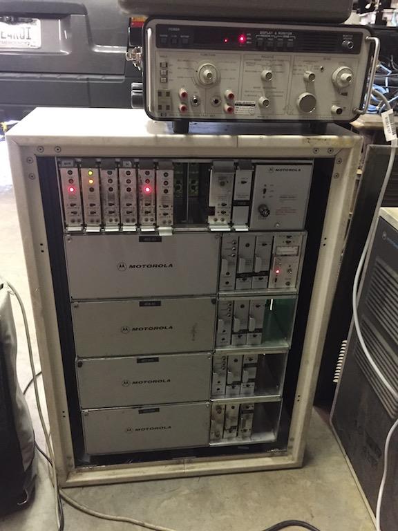
Here's the frame before alignment and after initial power up.
Each receiver line connects to the back of the comparator.
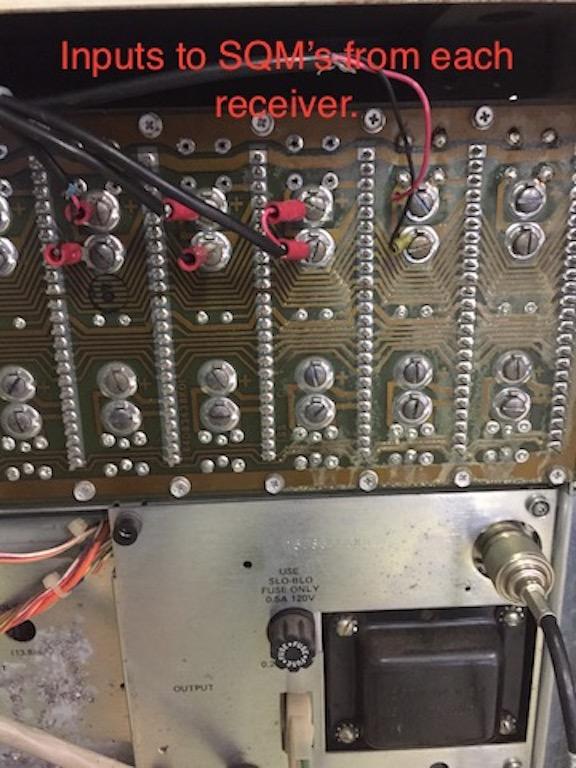
The Line Out connection point on the back of each receiver goes to the respective SQM input on the comparator.

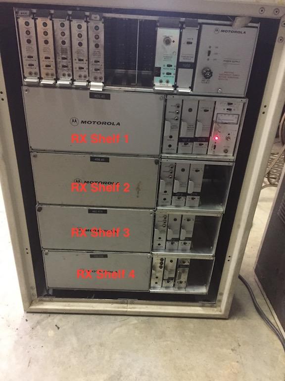
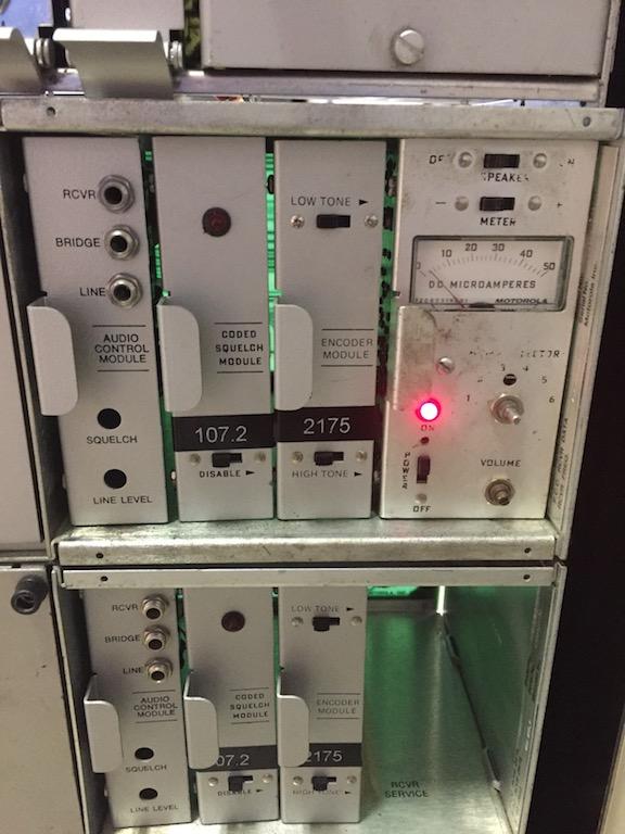
Here's the layout of my comparator cabinet.
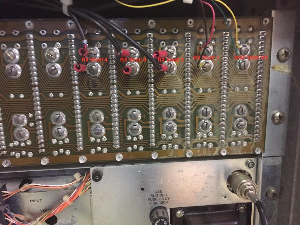
Here's the connection from each receiver and the MSF5000 on the comparator.
Initial Power Up and Tuning:
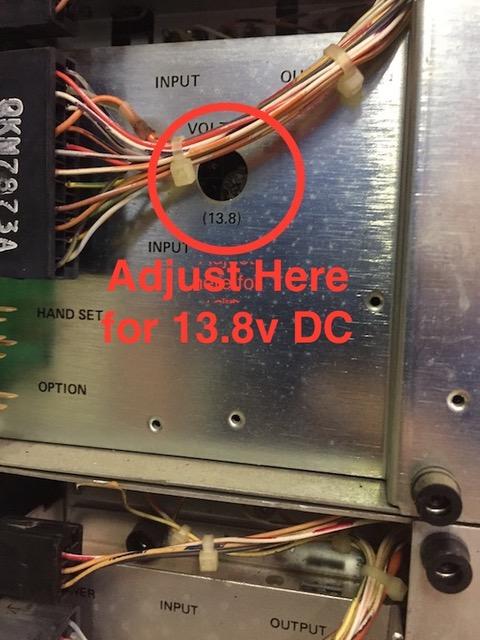
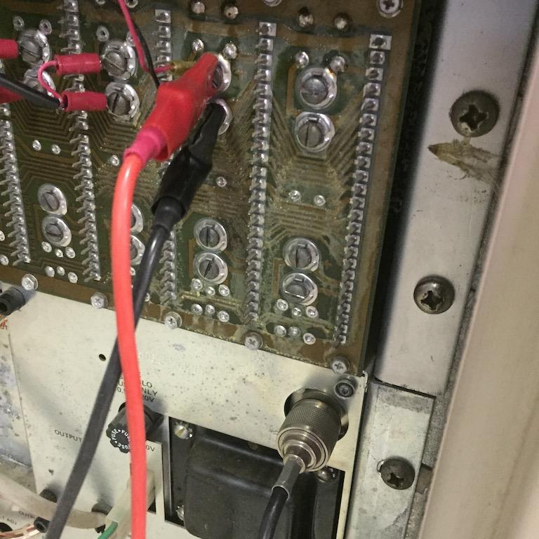
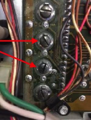
I inspected the backplane inside and out to look for cut traces and any wires from terminal to terminal as lots of these units were modified. I removed and/or fixed anything that did not look factory. Spark gaps are not important since we are not using the telephone company. I pulled all cards off the bus, powered up the cabinet and started the tuning process. First thing was to make sure each power supply was supplying 13.8v. I put a DVM on the A+ terminal on the backplane to the chassis (see photo below). Two of the three shelves voltages were slightly low. An A+ (13.8v) test point is on the receiver backplane. There's a similar test point on the comparator backplane.

Using the potentiometer on the back (see photo below), I turned up the voltage to the proper 13.8v. I pushed in each card one at a time making sure each card was not dead or causing a short. After every card was in place, I re-tested the voltage and made adjustments as needed. The 13.8v adjustment pot is accessed through a hole on the back of the power supply.
The next step was tuning the receivers. I didn't want to put forth the expense of ordering crystals for something I was not sure would even work or that I would even use. I decided to use the frequencies that were in the units from the public safety systems they originated from. This would be good for testing purposes and if all went well I could re-crystal at a later date or change the Micor RF section out for a portable or mobile that suppled raw audio. NOTE: Never use non-amateur or unlicensed frequencies in a live system or transmit. To tune the receivers, I used my R1033A test set. I used the Micor mobile cable (silver meter end) to plug into the metering port on each receiver board. The station had a service module TLN1717, but the meter was faulty. The speaker on the card worked just fine, so I used it to listen to my injected signals, moving it from shelf to shelf as I stepped though the tuning process. I left the audio control card (TRN6080B) and the PL decoder (TRN6083A) in place with the PL disabled, and I pulled out the encoder module (TRN6085B). I followed the tuning procedure in the Spectra TAC receiver manual (68P81026E31-C) for each receiver shelf. About all of them required minor adjustment.
Here's a view of the receiver shelf with all of the cards in place.
After all receivers were adjusted, it was time to set the jumpers on each card to work in a -13dB system. A -13dB system is a system that is configured with no loss such as a microwave mux and local receivers. A 0dB system is configured to compensate for losses when using telephone company equipment. Since all of our receivers and the MSF5000 were local to the voter, it all needed to be set up for a no-loss (-13dB) system.
Critical Jumper Settings:
Red arrows indicate jumper positions
Spectra Tac Receiver
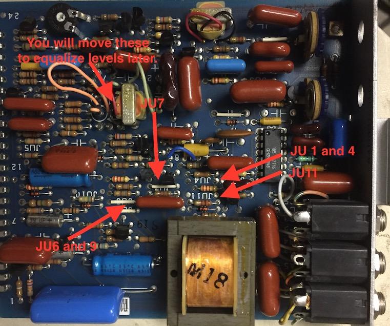
Audio Control Module TRN6080B
JU1: OUT (AND Squelch)
JU4: OUT (PL Squelch)
JU6: IN (Local control of line driver)
JU7: IN (600 ohm)
JU9: and 10 IN
JU11: OUT (Status tone deviation)
Audio Control Module jumper locations.
PL Decoder Module (TRN6083A)
JU1: IN (Normal PL) This would be OUT if using external PL
JU2: OUT (Normal PL) This would be IN if using external PL
JU3: IN (PL Indicate)
PL Decoder Module jumper locations.
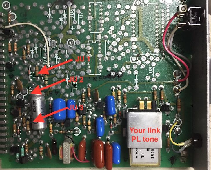
Install a PL tone reed for the PL you will be using, to avoid delays, use the same PL for the RF link as your repeater input.
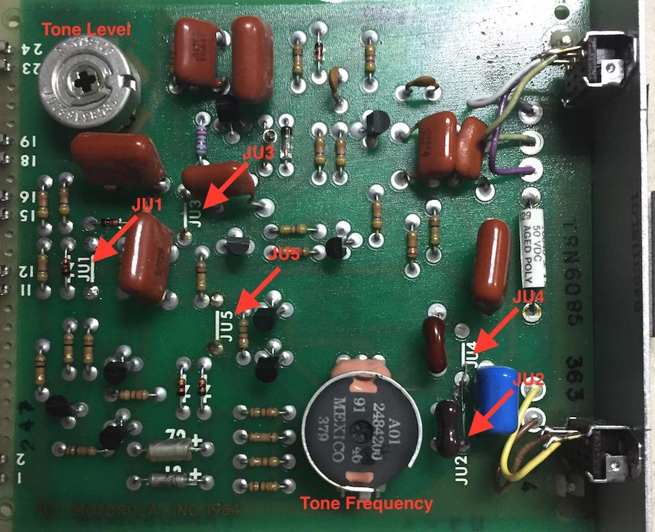
Encoder Module (TRN6085)
JU1 OUT (PL Squelch)
JU2 IN (2175 Status tone)
JU3 OUT (Status Tone Deviation)
JU4 OUT (2175 Status Tone)
JU5 OUT (Status tone Deviation)
Encoder Module jumper locations and set points.
Voting Shelf Jumpers
Interconnect board (Inside shelf on backplane, not on rear)
JU1: IN (No relay on tone) (I found both my jumpers cut)
JU2: IN (No relay on tone)
JU3: OUT (No tone priority module)
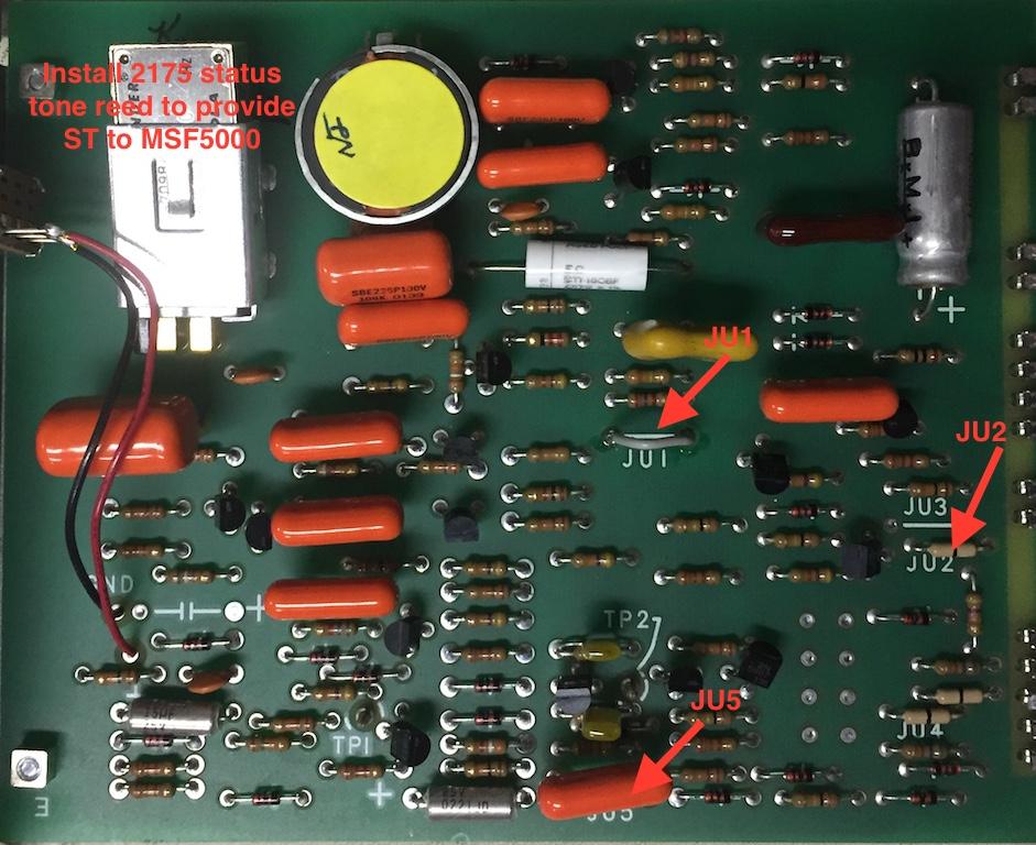
Tone Keying Module (TRN6095A)
JU1: IN (1950 function Tone for PTT)
JU2: IN (Dropout Delay or repeater hang time)
JU5 IN: (No guard tone keying)
Be sure to put a 2175Hz tone reed on this module.
Tone Key Module jumper locations.
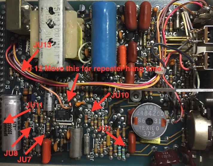
Command Module (TRN6093A)
JU1: OUT (2175 Status Tone)
JU7: OUT
JU8: OUT
JU10: IN (Tone Keying)
JU11: OUT
JU12: (Dropout Delay, default is 0, set for what you want, this is your repeater hang-time)
JU13: OUT (No mute on disable, if a card fails, it can still vote and pass audio)
Command Module jumper locations.
Signal Quality Module or SQM (TRN6091B)
JU1: Out (2175 Status Tone)
JU2: OUT (fail circuit active)
JU3: IN (15 second fail delay, since we are local, less chance of line failure)
JU4: OUT (-13dB Status Tone)
Signal Quality Module jumper locations.

C version cards have different jumpers.
JU1: Out (for -13dB)
JU4: IN (15 second fail delay)
Move JU2 to JU3 to adjust status tone frequency using R36.
Level Adjustments:
Now that the jumpers are set, it's time to do the line level adjustment. For this I used an HP 3551A Transmission Line Test Set. I set the unit for receive/terminate and clipped the leads to the back of the SQM connected to the receiver to tune (it's important that you leave the SQM plugged in to provide a 600 ohm termination). Measure at the SQM input to take into account any loss (very little if any) for an exact level input to SQM. Do not measure from the input jacks on the front of the audio control module; these are only for site checks and basic troubleshooting.
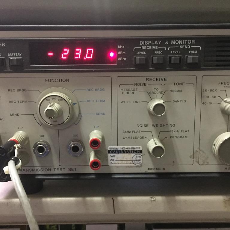
Here's where you measure the -10dBm receive level and -23dBm status tone on the back of the comparator.
The proper test set configuration to align the comparator and receiver.

I selected the frequency and checked the frequency being sent by the receiver. Make sure it is EXACTLY 2175 (+/- 1Hz). If it is not, use a nonmetallic tuning tool and an extender card (unless you have small hands) and tune the variable inductor at the top of the Encoder card (RED arrow below right) until you get 2175Hz. If the frequency won't tune, or jumps around a lot, the card is in need of repair.
Measuring the 2175 Hz status tone from the encoder when the receiver is quiet.
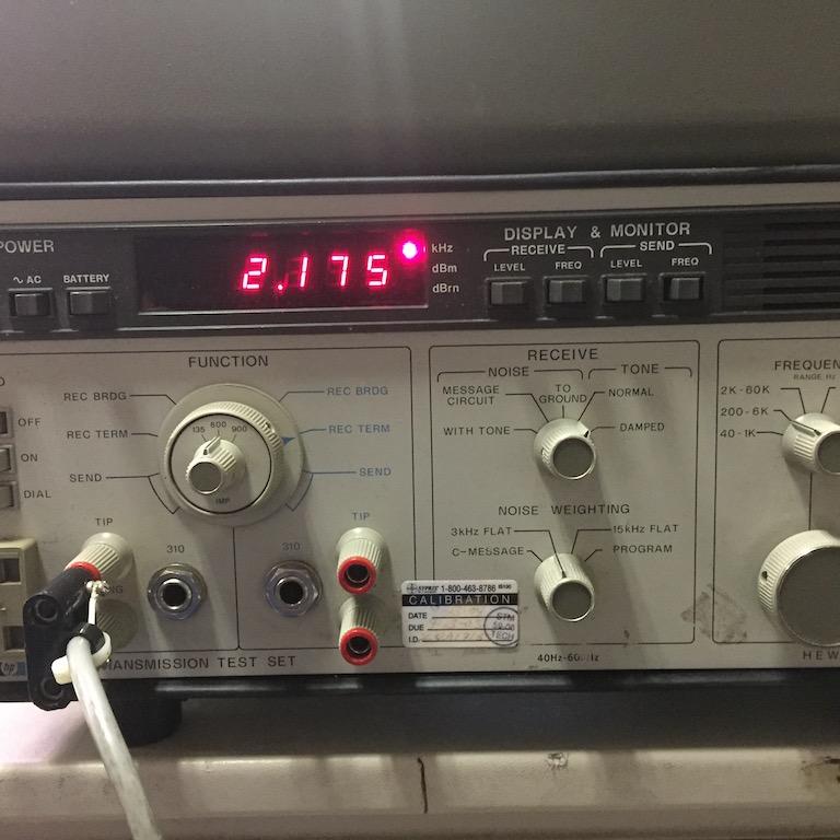
Alignment points on the encoder module. The pot pointed to by the blue arrow adjusts the status tone level; the core pointed to by the red arrow adjusts the status tone frequency.

Next, select level on the meter, disable PL, and inject a 1 kHz signal with PL at full quieting into the receiver at a 3 KHz deviation (the book says 5 but use 3; it gives you some room for different radios used by amateur radio users). Adjust the audio control module line level (front of the audio control module) to -10dBm into the SQM. Turn off your injected signal so that the 2175Hz status tone remains. Next, using the extender card, or a very small hand, adjust the line level (BLUE arrow in above picture) of the status tone on the encoder card to -23dBm (-13dBm below your audio). Finally, using the extender card on the audio control module, send the HIGH and LOW level test tones (switches on the front of the encoder) and move the jumpers to equal out the levels of your 1 kHz tone injected signal (-10dB). You will not be able to get them exact, but get them as close as possible. Do the above procedure for each receiver shelf. Note: If you change a card in the line path such as the encoder, audio control or even SQM, you will have to check and set the levels again for that receiver.
The comparator is partially working after initial alignment of the remote receivers but before the MSF5000 hookup. Remote receiver 4 had a bad encoder module causing the SQM to fail.

Here, the -23dBm status tone level is shown with no signal injected into the receiver.
With a 1 kHz signal at 3 kHz deviation into the receiver, the audio level is now -10dBm.

After every receiver shelf is adjusted, your voter should be functional. You can test this by injecting a signal into the power divider and seeing if the SQM votes, then you can change your generated frequency and see if the voter follows. Some things to consider: if your voter is still failing, you could have bad cards. I actually found six bad SQMs, two bad encoders, and two bad audio control modules so it never hurts to have extras. Some of these cards are in excess 20-30 years old and the capacitors will leak or dry out. Out of my bad SQMs, I found four with obvious leaking capacitors on the line circuit. Shelve those to repair later or use as parts. Contact cleaner is also a good thing to use on the switches and the tuning potentiometers. Leave the injected signal on each receiver and keep it voted for no less than five minutes. In doing this test, I found a bad encoder that would fail the SQM after about one minute of activity (possibly another bad cap). Another thing I stumbled on while troubleshooting bad cards was an audio control module with good status tone output levels but not when a signal was injected from the receiver. My old T1 days told me it may be the bantam jack on the front of the card. I sprayed contact cleaner in each jack, then took a bantam plug and ran it in and out of each port... bingo, now I have receive audio into my SQM.
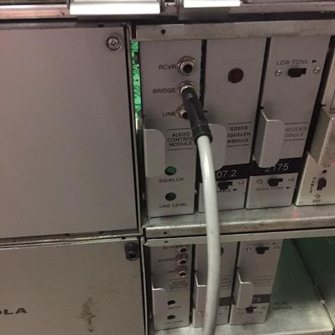
The test port bantam jack in use to monitor the receiver during a live test.
This identifies what each port will test or what you would expect to hear.
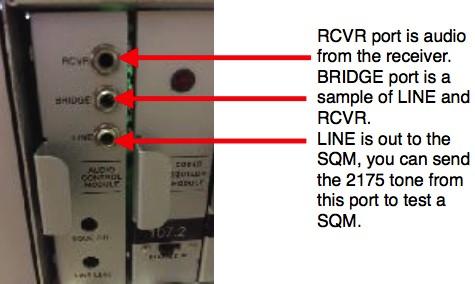
The ports on the front of the audio control module are good just to do basic troubleshooting but not to do a proper alignment.
Now it's time to tune the line out to the MSF5000 and test the tone-keying module. Inject a signal into any receiver and read the line level coming out of the command module at the LA+ and LA- terminals. Adjust the front of the command module to -10dBm out. Press the XMT switch on the front of the tone-keying module and listen for the function tone.
The terminals that connect to the MSF5000 LINE 1 port will carry the voted audio from the comparator to be re-transmitted.
MSF5000 Integration:
This procedure will only work on the CXB and RLB controller with a TTRC, the CLB requires an external expansion card.
Program the station using RSS for SPECTRA TAC by starting with the default codeplug definition file for conventional Spectra TAC and edit for your frequency and settings. Try not to alter any line interface settings. One thing you may want to change on the Spectra TAC page under Advanced Options is the Failover Delay setting that allows the repeater to use its own repeat control if the voter fails (make sure you have a status tone reed in the tone keying module).
Power Down the station.
Set all the jumpers on the TTRC to their normal position except for those in the list below:
JU4205: ALTERNATE (4 Wire Audio)
JU4222: ALTERNATE (4 Wire Interrupt circuit Line 2)
JU4228: ALTERNATE (-10dBm)
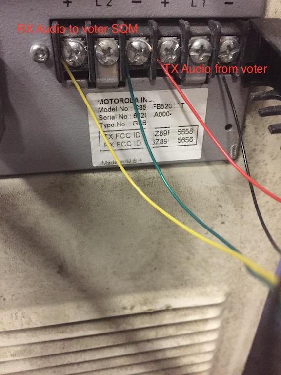
LINE 2 is RX Audio Out to the Spectra TAC SQM card terminals in the first slot (if that's what you desire). LINE 1 is TX Audio In from the Spectra TAC terminals LA+ and LA- on the bottom left of the voter backplane.
The terminals on the MSF5000 are your connection points to the comparator. LINE 1 will go to the LA terminals for transmit audio; LINE 2 will go to the back of the SQM for receive audio voting.
Make sure J900 on the TTRC is cabled to J1601 on the side junction box.
After you cable the station, power back it up. You will need to set the EEPOT Levels using your Transmission Line Set; I used my HP again for this task on line 1. Perform the alignment as stated in the 6881082E04 manual, chapter 4, page 7. You are going to basically do the same thing you did on your remote receivers: set your receive level on a 3 kHz deviated signal to -10dBm and your status tone to -23dBm.
EEPOT 8: adjust your status tone level (should be -23dBm)
EEPOT 9: adjust your high balance tone (as close to -10dBm as possible)
EEPOT A: adjust your low balance tone (as close to -10dBm as possible)
EEPOT C: adjust your receiver level output to the SQM, inject a 1 kHz signal at 3 kHz deviation
and adjust for -10dBm
Afterwards, check the line level into the MSF5000 on LINE 1 coming from the Spectra TAC by injecting an RX signal; make sure it is still at -10dBm. Listen for the PTT function tone and check to see if the station keys; it should. There should also be a yellow LINE PTT LED illuminated on the front of the TTRC. If the yellow LED is not lit and the station is keyed, the local controller has taken over, check your line into the MSF and check for the PTT tone. Try injecting into one of the other link receivers and see what happens. I switched through all of the receivers with my service monitor to see if the audio was close to the same.
Here's the comparator after alignment, being tested with injected signals at different levels.

Acknowledgements and Credits:
Spectra TAC, MSR2000, Micor, MaxTrac, and MSF5000 are trademarks of Motorola, Inc.
HP is a registered trademark of Hewlett Packard, now Keysight Technologies.
Jumper settings, alignment, and wiring came from respective service manuals.
Thanks to Bob WA1MIK for converting this PDF file to an HTML article for repeater-builder.
Contact Information:
The author can be contacted at: stump_andy [at] yahoo [dot] com.
Back to the top of the page
Up one level
Back to Home
This page originally composed on Sunday 07-May-2017.
Photographs, article text, and layout © Copyright 2017 by Anthony Stump KE4KQI. All photographs were taken by the author.
This web page, this web site, the information presented in and on its pages and in these modifications and conversions is © Copyrighted 1995 and (date of last update) by Kevin Custer W3KKC and multiple originating authors. All Rights Reserved, including that of paper and web publication elsewhere.