Back to Home
By Robert W. Meister WA1MIK

|
Up one level Back to Home |
Adding a NorComm NC113 DPL Board to a Motorola Spectra TAC Receiver By Robert W. Meister WA1MIK |
|
I found this board - NorComm NC113 - on a popular auction site for $5.00US plus first class priority mail shipping. I bought two of them on Monday and received them two days later. Each board came with its own 10-page printed instruction manual. I requested a PDF copy of the documentation from NorComm; they quickly sent it to me. It can be downloaded here as a 500kb PDF file. The board claims it can encode and decode Digital-Coded Squelch (DCS) signals. Motorola's trademarked name for this technology is Digital Private-Line (DPL).
The intent is to wire this DPL board up as a decoder and attach it to an existing stock Spectra TAC receiver TRN6083A PL decoder board, retaining the existing features and signals present on the PL board. This unit will be used as a link receiver for a split-site repeater, replacing a MaxTrac receiver.
When completed, either PL or DPL will be decoded and will open the squelch circuit. It is certainly possible to add a switch to select PL or DPL decoding; that is left as an exercise for the reader. In the mean time, if you don't want PL to be decoded, remove the PL reed. If you don't want DPL to be decoded, disconnect the input wire. It's not recommended that both PL and DPL be transmitted by a radio simultaneously, as the two coding schemes are not compatible.
NC113 Features:
The board encodes and decodes one DPL code. You can program the board to any of the 176 valid codes using a set of eight switches. The documentation consists mainly of switch settings. You can't select an invalid code; the board uses a lookup table that translates the binary switch pattern to the appropriate DPL code. (Com-Spec makes a similar board - the DCS23 - that has nine programming jumpers, letting you enter any octal DPL code from 000 to 777, most of which are invalid.) I haven't tested it yet, but I hope the unlisted codes are ignored. The factory default code is 023 and I verified this with my DPL test set.
A decoder output signal is not brought off the board, but it certainly could be. Instead, they wire it up to the manual ENC switch (push it to force encoding) through an isolation diode so the board automatically encodes the same DPL code whenever it detects the decode code. This is the only diode on the board and it's next to the SIP switch; the component layout does not show it.
You can independently set the transmit or receive code to be normal or inverted, however as there's only one way to program an actual DPL code, the board will encode the same code that it decodes. It merely regenerates a nice clean version of it. (There's a newer version of this board called the NC005 that has additional capabilities, including the ability to select a different encode code. I suspect the NC113 can do this as well.)
There's a red LED that illuminates when the board decodes the correct DPL code. Similarly, there's a green LED that illuminates when the board is transmitting, either the programmed DPL code or the Turn-Off Code (TOC). In my opinion, these colors are reversed. Red should indicate transmit and green should indicate receive, but I didn't build or design this unit. A manual ENC (encode) push-button switch causes the board to transmit, just as if it had decoded a DPL code itself.
The manual says the board will output various audible tones during programming. I never heard any tones emitted from the transmit data line on the two boards I purchased; perhaps they come out the high-pass audio output line, which I never monitored. The code programming process went smoothly and very quickly. I toggled the switch closed, waited maybe one second, then opened it, and the new code took effect. This board was designed to plug into some older RELM repeaters. Perhaps the tones are audible when used in the manner for which it was designed.
I did have to completely reset one board to factory settings when I got it, as it was stuck in some kind of mode where it was decoding a signal but would not encode anything. It's probably wise to reset any board you get before using it for anything else. This may have also been due to the reset signal problem documented at the end of this article.
NC113 Performance Parameters:
I connected my DPL test set (SLN-6413) to the board, set the code to 023, normal polarity for both encoding and decoding, applied +9.6V and ground, and the board came to life. The red LED lit up, indicating the presence of a correct DPL signal. The green LED lit up, indicating the board was now transmitting the same DPL signal. I verified this with a voltmeter and an amplified loudspeaker connected to the yellow data wire. When I removed the incoming signal, the red LED turned off but the green LED stayed on for about another 0.2 seconds while the board transmitted the 134 Hz TOC. No transmit signal came out once the green LED turned off. The PTT output line is pulled up to +5VDC when idle and pulled down to +0.17VDC when transmitting.
The decoder minimum signal amplitude was about 3mVrms. Of course, this is with a perfectly clean signal. It probably will need a bit more when receiving a real radio signal.
The encoder output level reached about 900mVrms at the maximum setting of the pot. Here's a scope trace of the AC-coupled output signal, which is carried off the board by a separate yellow transmit data wire:
I also captured a trace of the turn-off code, which should be a 180msec burst of 134.4 Hz tone:
Current draw at +13.6V was 11 mA when idle, 25 mA with the manual ENC push button pressed (encode only), and 27 mA when decoding and encoding a signal with both LEDs on.
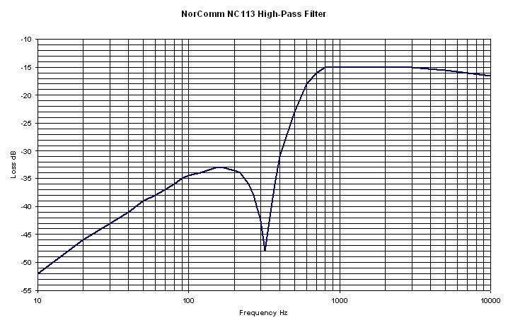
The built-in high-pass filter seems to have an awful lot of loss: 15dB at 1000 Hz and higher. I would have expected 0dB loss in the pass-band. There's a big notch at 330 Hz. It would seem to be capable of removing the sub-audible signals. See the graph below for the actual response.
Spectra TAC PL Decoder Board Performance:
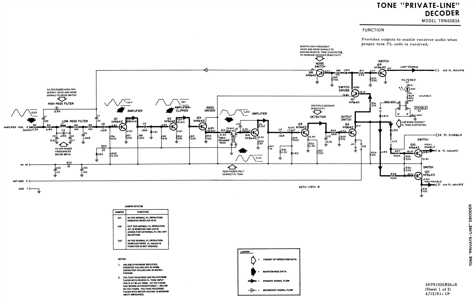
The schematic indicates a nominal 60mVAC audio input signal level. The two outputs from the board are called PL Indicate (pin 16) and AUX PL Indicate (pin 21); both pull their respective lines up to A+ when the correct PL tone is decoded. Here's the schematic of the board:
The table below shows the audio level, in millivolts, at both discriminator audio pins, with a 100.0 Hz modulating tone, at various deviation levels. Pin 3 is what Motorola calls "Amplified Discriminator Audio" and it also has 3-4VDC present on it, while pin 10 is just plain "Discriminator Audio" and it also has about 5VDC present on it; this voltage varies slightly as the receiver input carrier frequency changes. The PL board uses the amplified audio signal from pin 3. The 900 MHz Spectra TAC receiver is narrow-band (±2.5 kHz) but the rest of the chassis is wide-band (±5 kHz); the 450 MHz chassis is entirely wide-band (±5 kHz). Components on the Spectra TAC Audio/Squelch board are changed to accommodate differences in recovered audio levels. The cells in green are the ideal PL/DPL modulation level. What's important from this data is that the NorComm board will have plenty of signal available.
| Dev kHz | 900 MHz | 450 MHz | ||
|---|---|---|---|---|
| Pin 3 | Pin 10 | Pin 3 | Pin 10 | |
| 0.0 | 3 | 1.7 | 10 | 5 |
| 0.1 | 37 | 18 | 32 | 16 |
| 0.2 | 74 | 37 | 62 | 31 |
| 0.3 | 111 | 55 | 92 | 46 |
| 0.4 | 147 | 73 | 122 | 61 |
| 0.5 | 184 | 92 | 152 | 76 |
| 0.6 | 221 | 110 | 183 | 91 |
| 0.7 | 258 | 129 | 213 | 106 |
| 0.8 | 297 | 149 | 244 | 121 |
| 0.9 | 335 | 167 | 274 | 137 |
| 1.0 | 372 | 186 | 305 | 152 |
The two primary outputs are "PL Indicate" on pin 16 and "Aux PL Indicate" on pin 21. Both of these have 0.0VDC with no input signal and +13.3VDC with a proper PL tone detected. A third signal on pin 2 is also named "Aux PL Indicate" but it is an open collector transistor that requires an external pull-up resistor. This output is low when no PL tone is detected and floats high with a proper PL tone.
Q5 collector sits at 0.0VDC with no PL signal and rises to +9.7VDC when a PL tone is detected. This turns on Q6, which activates Q7, Q8, Q9, Q10, and Q11. When I manually pulled Q5 collector to +5V, which would be done by the NC113 board, Q6 and everything after it also turned on.
Available Spectra TAC Signals:
The existing Spectra TAC PL Decoder board obviously uses A+ (nominal 13.8VDC; my chassis measured 13.82VDC) and ground. It has one input: Amplified Discriminator Audio, which has DC present on it. It provides several outputs, but only one is used by the Spectra TAC Audio/Squelch board to open the audio path and turn off the idle tone when a signal with the proper PL tone is received. Here's a list of the signals and pin numbers on the Spectra TAC chassis backplane (BP) and the pins that make use of them on the stock PL and DPL decoder boards:
| Signal Name | BP | PL | DPL |
|---|---|---|---|
| Ground | 1 | 1 | 1 |
| Amplified Discriminator | 3 | 3 | 3 |
| +9.6VDC | 8 | -- | -- |
| Not Used | 9 | -- | -- |
| Discriminator | 10 | -- | -- |
| Receiver Unsquelched | 11 | 11 | 11 |
| A+ (+13.8VDC) | 12 | 12 | 12 |
| PL Indicate | 16 | 16 | 16 |
| DC+ (Aux PL Indicate) | 21 | 21 | 21 |
| DC- (PL Disable) | 22 | 22 | 22 |
| Aux PL Ind. (O.C.) | -- | 2 | 4 |
Only the pins indicated on the board schematics are listed, even though other signals may be present and available. Pins 21 and 22 run directly to screw terminals on the backplane.
Coincidentally, the NC113 board can operate with just these same four signals. The A+ and ground are universal; the board can handle 5-20VDC. The board can deal with as little as 3mV of audio and it's AC-coupled, so it won't care about the DC. An output signal will have to be created, as the board doesn't have any signal that's not already pulled up to +5V. The red LED drive signal goes low when the correct DPL code is detected, and I need to eventually pull some signal on the Spectra TAC board high to turn on its PL Indicate outputs. A simple PNP transistor inverter will be used to accomplish this.
Speaking of signals, here's a breakdown of the Molex connector signals on the NC113:
| Pin | Signal Name |
|---|---|
| 1 | High-Pass Audio Output |
| 2 | Decode Audio Input |
| 3 | A+ Input |
| 4 | PTT Output |
| 5 | Ground |
| 6 | N/C (see text below) |
| 7 | Ground |
| 8 | N/C |
| 9 | N/C |
| 10 | Ground |
| 11 | N/C |
| 12 | Ground |
Hooking Everything Together:
The 12-position Molex connector mates with standard 0.156-inch pins. Several pins are not used. Rather than buy a matching connector, I would suggest taking some #20 stranded wire, strip off 3/8 inch, tin the ends, and stuff them into the necessary pins. Only four wires are needed for this application.
No modifications are necessary to either the NC113 or the Spectra TAC board, however one resistor (3.3k 1/4w) and one small silicon PNP transistor (2N2907), will be added to extract an output signal from the NC113 board that will activate the PL board. It's easiest to mount these on the NC113 board and bring the signal out through one of the unused Molex connector pins. I've chosen to use pin 6 for this purpose. Here's a schematic of the parts being added to the upper right corner of the NC113 schematic, across R15, which is 560 ohms on my boards:
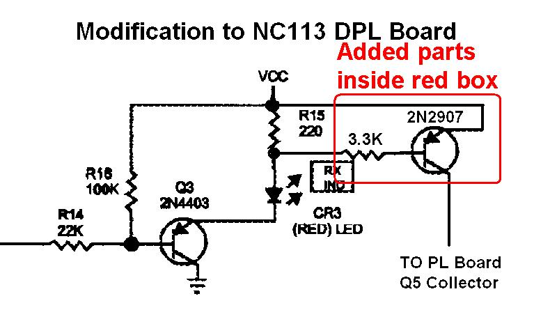
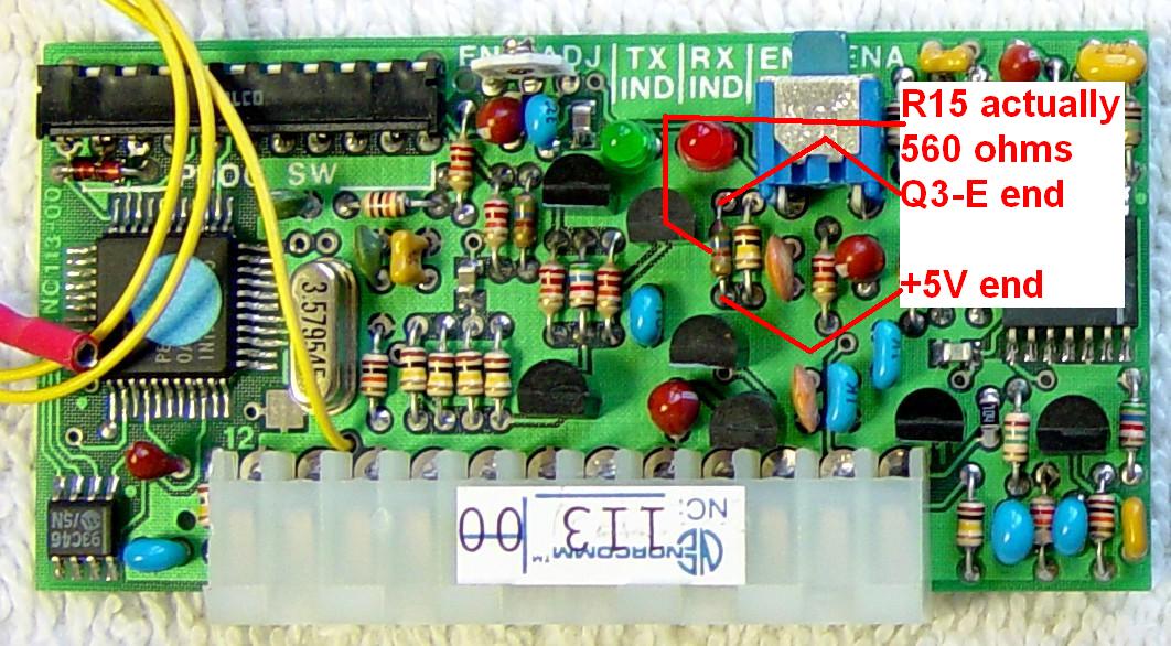
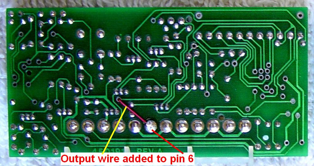
The transistor emitter goes to +5V, the end of R15 closest to the Molex connector. The transistor base goes through a 3.3k resistor to the other end of R15. The transistor collector is brought out through a small piece of #30 wire-wrap wire, passed through a feed-through hole, and soldered to pin 6 of the Molex connector underneath the board. I could have tried to attach this wire to pin 6 on top of the board, but it seemed neater to run it underneath. Here's a photo of the top of the original board followed by one of the modified board:

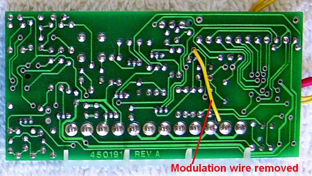
Since I won't be using the encode portion of the NC113 board, I unsoldered and removed the yellow output wire. Here's a photo of the bottom of the original board followed by one of the modified board:
The signal we've brought out to pin 6 will be pulled to +5V when the proper DPL code is detected. This will then turn on Q5 on the PL board, just as if a PL tone had been detected. Refer to the PL board schematic above. Here's an X-ray view of the PL board showing the various component locations. Remember, this is viewed from the solder side of the board.
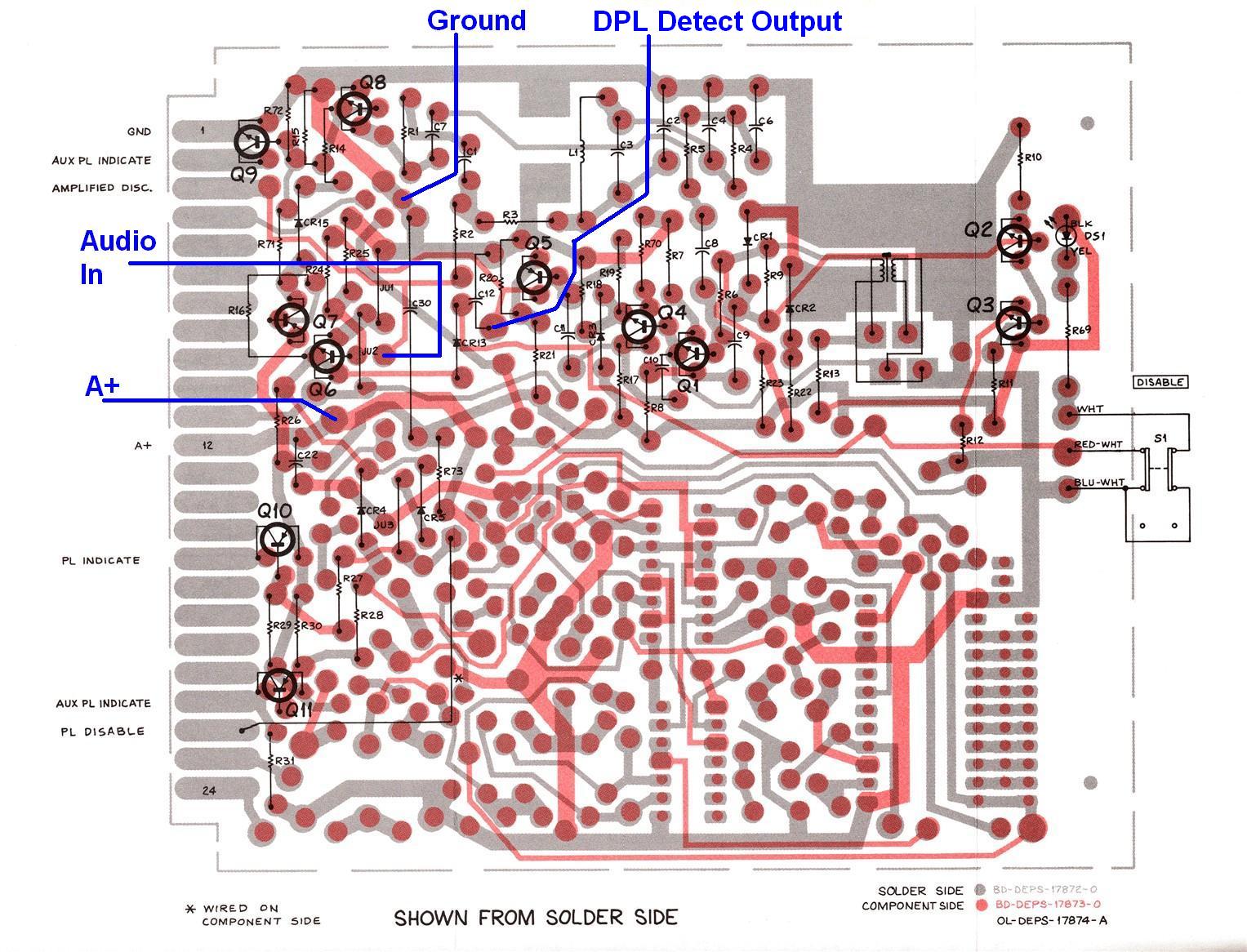
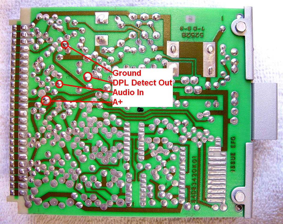
Here's a real photo of the back of the board with the above points indicated. I removed the solder from the holes and stuffed yellow #20 Teflon-insulated wire into each one. For the connection at C12, I removed the capacitor lead from the hole, wrapped the wire around the lead, and pushed it back into the hole. I then soldered both sides of the board.
The following table summarizes the connections between the DPL board and the PL board.
| Signal Name | NC113 | Spectra TAC PL Board |
|---|---|---|
| Ground | Pin 10 | Ground (upper end of C30) |
| A+ (power) | Pin 3 | Test point at pin 12 |
| Audio Input | Pin 2 | Test point next to JU2 |
| DPL Detect Out | Pin 6 | Q5 Collector (lower end of C12) |
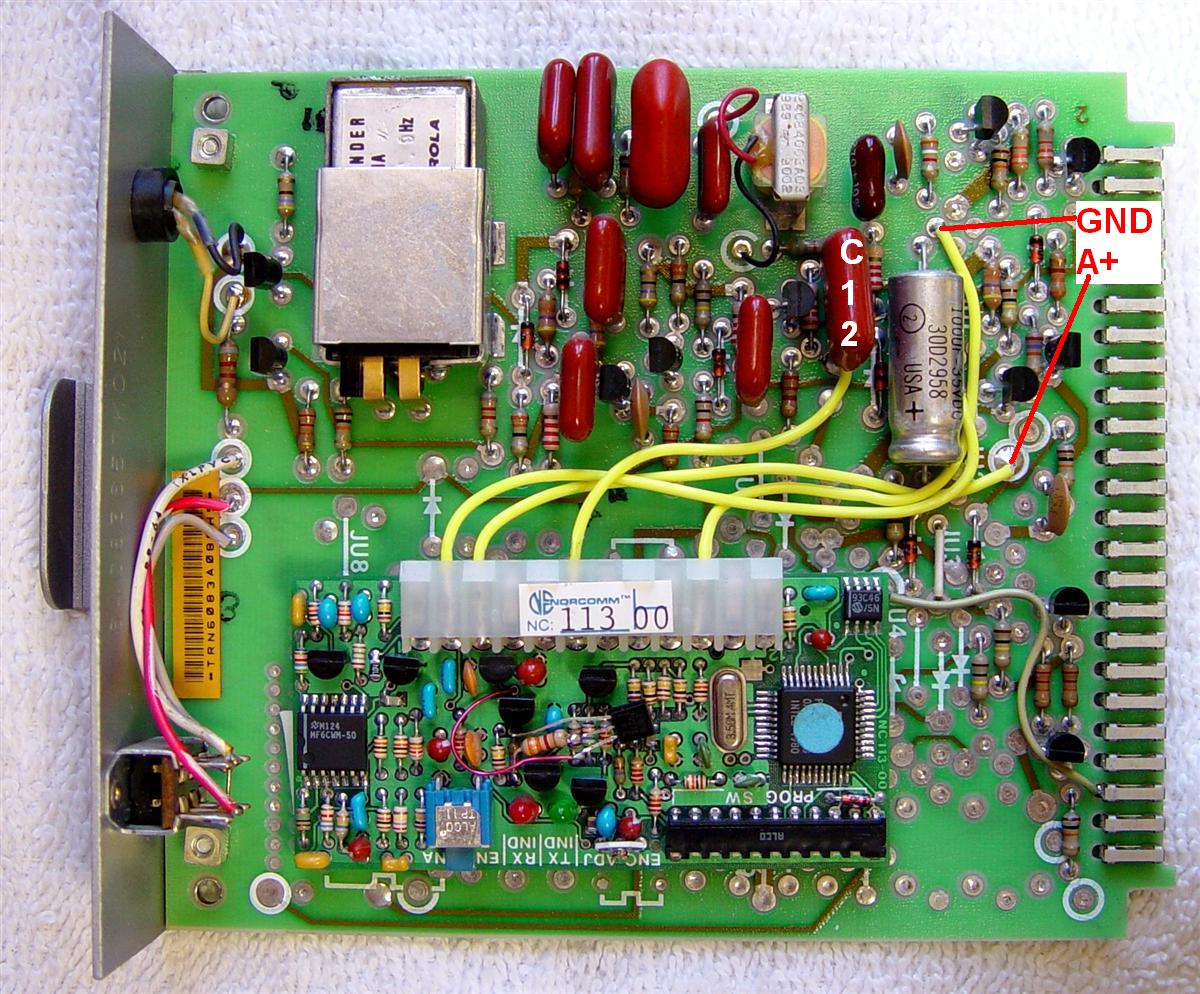
Here's a photo of the completed assembly. I used two layers of double-sided foam tape under the NC113 board to adhere it to the Spectra TAC PL board. You can't see all of the connection points unfortunately.
Results:
Both boards respond to either the correct PL tone or the correct DPL code. However, the DPL board seems to be very sensitive to how fast the power supply comes up. When I plug the Spectra TAC's AC power cord in, the NC113 board will come up with one or both LEDs lit up, or none at all, but will not decode a DPL signal. If I plug the board in "hot", with power already present in the Spectra TAC chassis (a procedure that's not recommended) everything works just fine. This is not good.
I put an oscilloscope on the +13.8VDC power lines and discovered that the voltage takes about 250msec to come up to full voltage. I put the scope on the CPU's Reset signal input (bottom end of R4 on the NC113 board) and found a 0.5V pulse about 75msec wide. This is definitely NOT resetting the CPU, hence it comes up any way it wants without being properly reset. When I plugged the board in with power already present, the reset pulse reached 4.6V and was about 5msec wide. I believe the small value of C1 was charging about as fast as the +13V power supply was rising, so the net result was no reset signal for the CPU.
I added a 22uF, 16V aluminum electrolytic capacitor (it was the first one I grabbed that had long leads) across the existing C1. The positive end went to the right side of R2, next to the hole where the yellow wire was removed (towards the middle of the board). This is a source of +5VDC. The negative end went to the bottom end of R4, closest to the Molex connector. Essentially this capacitor is now across C1 and it extends the reset signal considerably. Here's a photo showing the capacitor installed on one board:

Now when the board is plugged in, the green LED lights for a few hundred milliseconds, but the board resets every time. The reset signal is now nearly 500msec long and reaches nearly +5V. Problem solved. I performed this modification on both boards and they are both reliably resetting now.
Test Equipment Used:
Acknowledgements and Credits:
PL, DPL, and Spectra TAC are trademarks of Motorola, Inc.
NorComm, NC113, and NC105 are trademarks of NorComm Corporation. Unfortunately NorComm ceased business, closed its doors, and emptied its web page in 2017.
Molex is a trademark of Molex, Inc.
Teflon is a trademark of E. I. du Pont de Nemours and Company.
Thanks go to Dave N1OFJ for loaning me his 450 MHz Spectra TAC chassis for analysis and testing of the NorComm DPL board and its subsequent installation.
Contact Information:
The author can be contacted at: his-callsign [ at ] comcast [ dot ] net.
Back to the top of the page
Up one level
Back to Home
This page originally posted on Sunday 11-Apr-2010.
Photographs, article text, and hand-coded HTML © Copyright 2010 by Robert W. Meister WA1MIK. All photographs were taken by the author.
This web page, this web site, the information presented in and on its pages and in these modifications and conversions is © Copyrighted 1995 and (date of last update) by Kevin Custer W3KKC and multiple originating authors. All Rights Reserved, including that of paper and web publication elsewhere.