Back to Home
Motorola Spectra TAC
Receiver Service Module
By Robert W. Meister WA1MIK

|
Up one level Back to Home |
Improving the Motorola Spectra TAC Receiver Service Module By Robert W. Meister WA1MIK |
|
Background:
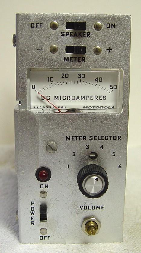
I purchased a receiver service module for my Spectra TAC receiver chassis. The board is stamped TRN6087A but the service manual (6881039E45) calls for a TLN1717A. These modules contain a 50uA meter, a six-position meter selector switch, several slide switches, an LED, a small audio amplifier, and a loudspeaker. There's a front panel volume control that has a screwdriver slot for adjustment. I have no idea why Motorola didn't use a normal pot with a knob for this feature, and after ruining a lot of fingernails trying to adjust the volume (when a screwdriver wasn't handy), I finally got fed up and replaced it. Here's a photo of the original module with the slotted shaft pot down at the bottom.
Parts Information:
The original part is marked 18X867272-V. The service manual part number is 18-867272 and is specified as "R3 - 25k ohms, 20%". I measured mine at 27k ohms with an audio taper. I found an equivalent potentiometer with a 1/8 inch diameter shaft by looking through the Mouser catalog, p/n 774-270X232A253B2A1. They also have an identical pot with a linear taper; replace the "B2A1" at the end of the part number with "B1A1". Either one cost about $2.75US. I selected an appropriate knob for a 1/8 inch diameter shaft, Mouser p/n 506-PKG40B1/8 that cost about $1.55US.
Changing the Pot:
Replacement of the pot is straightforward and it begins by removing the module from the chassis. Write down where each lead goes (they are color-coded), unsolder all three leads from the pot, remove the mounting nut from the front of the service module, and remove the old pot.
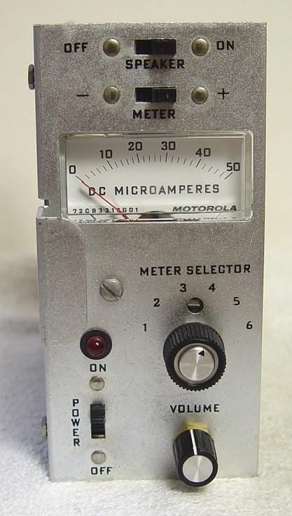
You must do some preparation to the new pot before installing it. Cut the shaft with a hacksaw (it's brass and cuts very easily) so 3/8 inch remains. Bend the small anti-rotation tab in the front of the new pot (this would normally fit into a hole in a panel to prevent the pot from rotating) so it won't hit the front panel, install the new pot with its supplied hardware (the internal-tooth lock washer goes behind the front panel), reattach the new wires, and install the knob, positioning it so the pointer is aligned properly. Reinstall the module into the Spectra TAC chassis. This all took under half an hour. Here's a photo of the module with the new pot and knob. Not too shabby, eh?
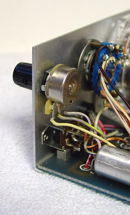
It looks just about the same from the back except the new pot has printed circuit board terminals rather than solder lugs. I just stripped the old wires, tinned them, bent them around the terminals, and soldered them on.
Acknowledgements and Credits:
Motorola and Spectra TAC are trademarks of Motorola, Inc.
Contact Information:
The author can be contacted at: his-callsign [ at ] comcast [ dot ] net.
Back to the top of the page
Up one level
Back to Home
This page originally posted on Tuesday 04-May-2010.
Photographs, article text, and hand-coded HTML © Copyright 2010 by Robert W. Meister WA1MIK. All photographs were taken by the author.
This web page, this web site, the information presented in and on its pages and in these modifications and conversions is © Copyrighted 1995 and (date of last update) by Kevin Custer W3KKC and multiple originating authors. All Rights Reserved, including that of paper and web publication elsewhere.