Back to Home
Audio Filter and Equalization
Frequency Response Analysis
By Robert W. Meister WA1MIK

|
Up one level Back to Home |
Motorola Spectra TAC Receiver Audio Filter and Equalization Frequency Response Analysis By Robert W. Meister WA1MIK |
|
One repeater I'm involved with replaced a UHF GM300 radio with a UHF Spectra TAC receiver. I immediately noticed that we could now hear the PL tone coming through the system and the audio had a lot more low frequency response. Curiosity got the better of me so I looked at the schematic of the receiver's Audio Control Module (ACM). Here's a partial scan of the audio section of that board (it's very wide):
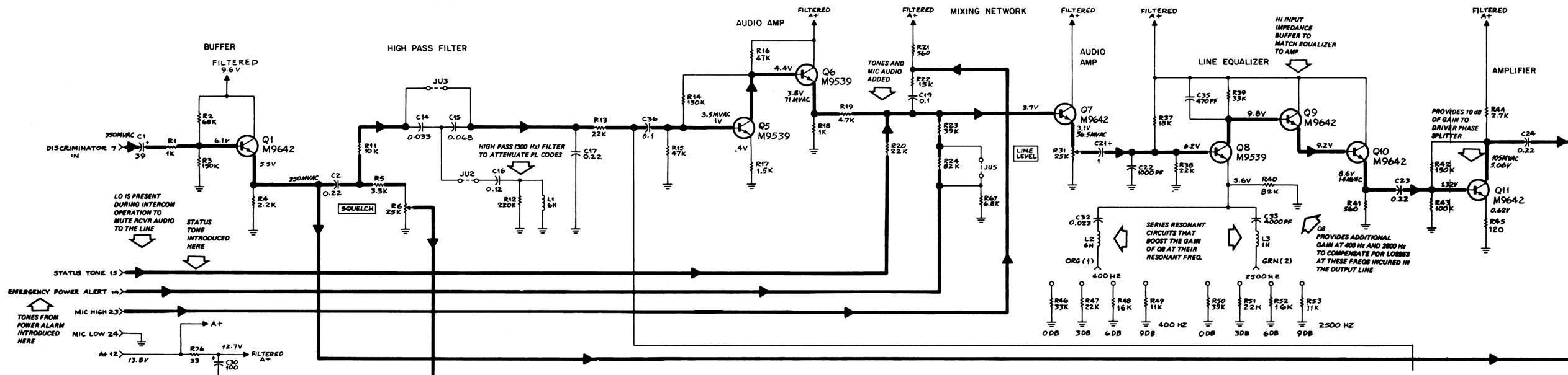
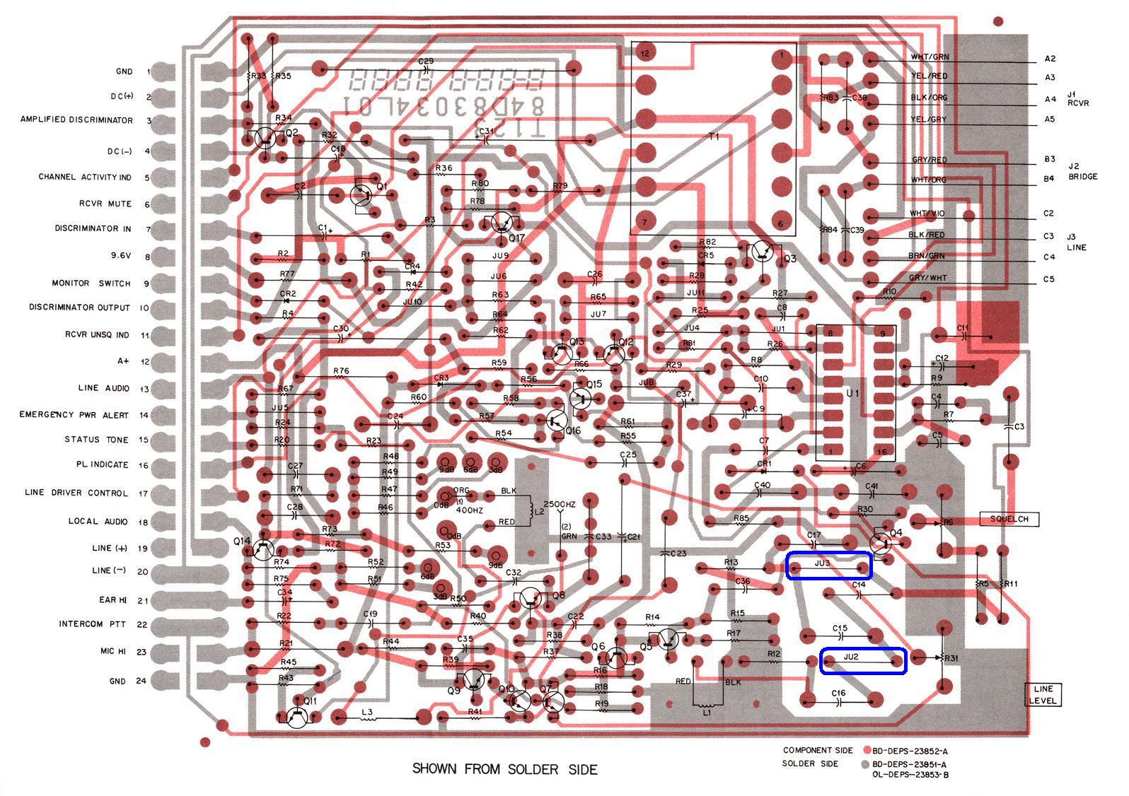
There is a high-pass (PL) filter that can be enabled or disabled by changing two jumpers, JU2 and JU3. (I've only worked on two other Spectra TAC receivers and they both had it enabled, as did the one I used for the test.) The link receiver chassis was brand new to the system and I suspected the filter is disabled on that unit's board. The two jumpers are enclosed in the lower right area of this X-ray view of the board, shown from the back.
Being inquisitive, I decided to plot the frequency response to see how effective this filter was at removing PL signals. While I had my chassis on the bench I also plotted the response of the low and high frequency equalization jumpers. Note that my ACM is the newer version that uses a potentiometer (which replaces L3) rather than jumper settings for the high frequency adjustment.
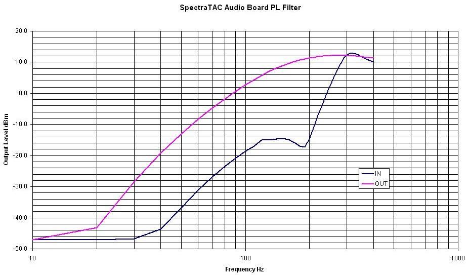
High-Pass Filter Response:
To measure the high-pass filter, I fed a modulated signal into the receiver in the Spectra TAC chassis and measured the audio level at the output of the ACM. A 600 ohm terminating resistor was strapped to the output terminals and I used +10dBm at 400 Hz as a reference level. I swept the modulating frequency in 10 Hz steps from 10 to 400 Hz, recorded the output level, and graphed the results, shown below. Then I switched the settings on JU2 and JU3 and ran the data again. The board's de-emphasis circuit (C17) started rolling off the frequency response above 400 Hz.
Equalization Circuit Response:
I fed an unmodulated 0dBm RF signal into the receiver (to fully quiet it) and fed a separate audio signal into the local microphone input (pin 23) of the ACM to bypass the de-emphasis and high-pass filter circuitry. The output level was monitored with the same setup as above. I adjusted the high frequency equalization pot for a reasonably flat response (roughly centered). I then recorded and graphed the results in 100 Hz increments as the low frequency jumper was moved to each setting. Note that this jumper only increases the gain at the low frequencies.
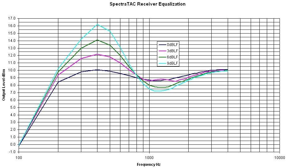
Even though the jumpers are supposed to make changes in 3dB increments, my board was closer to 2dB per position. Also, the board's maximum output level is about +16dBm and I had to rerun some of the measurements at a lower level to escape the clipping that was occurring. The graphs do not reflect this limitation.
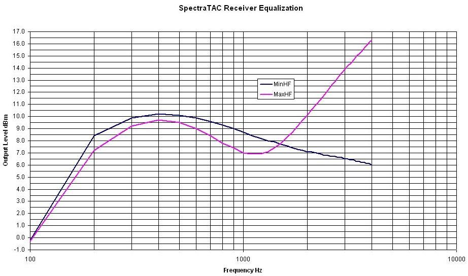
I did a similar sweep with the low frequency equalization set at 0dB and the high frequency pot set at its two extremes. Note that this pot can both increase and decrease the gain at the high frequencies.
Acknowledgements and Credits:
The schematic diagram of the Audio Control Module came from the Motorola Spectra TAC Receiver Reference Manual, 6881038E45.
Motorola, Spectra TAC, PL, GM300, and a whole bunch of other terms are trademarks of Motorola, Inc.
Contact Information:
The author can be contacted at: his-callsign [ at ] comcast [ dot ] net.
Back to the top of the page
Up one level
Back to Home
This page originally posted on Tuesday 14-Oct-2010.
Graphs, article text, and hand-coded HTML © Copyright 2010 by Robert W. Meister WA1MIK.
This web page, this web site, the information presented in and on its pages and in these modifications and conversions is © Copyrighted 1995 and (date of last update) by Kevin Custer W3KKC and multiple originating authors. All Rights Reserved, including that of paper and web publication elsewhere.