Up two levels (Moto index)
Back to Home
By Nick Markovich N2XFX

|
Up one level (Spectra index) Up two levels (Moto index) Back to Home |
Adding a COR Signal to the Spectra DA-15 Accessory Connector By Nick Markovich N2XFX |
|
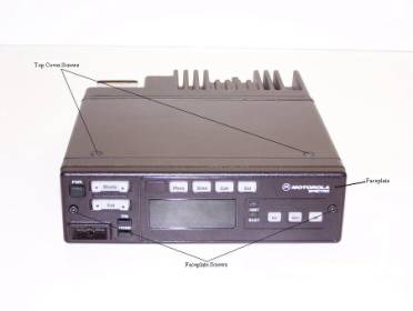
At the rear of the Motorola Spectra Radio there is a female DA-15 connector which is used for connecting the speaker, programming the radio and there are optional connections as well. The signals on this connector can also be useful for interfacing repeater controllers, link radios, IRLP Nodes and more. From the factory there is no COR signal on that connector. I'll try to give one method of routing a pseudo COR to one of the pins (I used the VIP 1 pin).
Please read this entire article first. If you can't do micro soldering do not attempt this modification.
Modification Procedure:
(1) With a torx #10 or a 2.5mm Allen wrench remove the 2 screws holding the faceplate
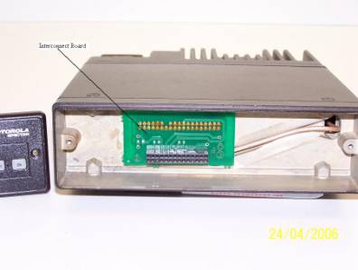
and gently pull the faceplate straight out. There is an interconnect board which then
needs to be removed. This also pulls straight out but check the pins after you remove
this and straighten them if needed.
(2) With a torx #15 remove the two screws in the top cover and remove the top cover by lifting the front while sliding forward.
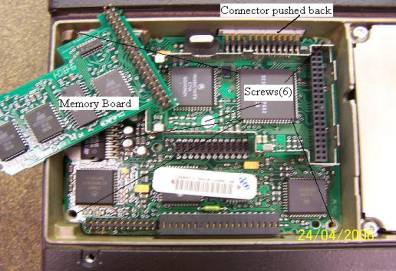
(3) Slide off the regular clip, slide back the ribbon connector, remove the memory board shield cover, and carefully remove the memory board and remove 6 screws (torx #15)
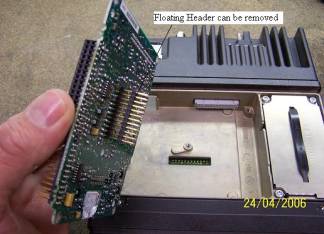
(4) The Command Board can now be removed by gently prying upward starting from the front but trying to lift up evenly (there is a floating header underneath you cannot see yet).
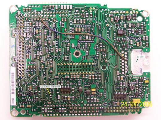
(5) Solder a piece of 24 insulated wire from pin 10 of U450 to pin 19 of P503 as shown. This is the hardest part as there is no room between pins/traces.
(6) Check that Jumper JU503 is not present. Usually this is the factory default. It would be a zero ohm chip resistor if it is present.
(7) Make sure the wire does not interfere with the center mounting screw hole and that it lays somewhat flat
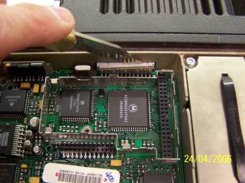
(8) Reassemble in the reverse order. Watch the alignment of the floating header as you plug the board back in, and the front ribbon cable connector can be helped along with knife or a small sharp screwdriver as shown below
Miscellaneous Notes:
There will now be a 12 volt active high on pin 12 of the DB 15 connector at the rear of the Spectra. This signal at U450 pin 10 is not a true COR - it is the high-going enable signal for the audio power amplifier (the speaker amplifier). This signal will follow what the channel is programmed for - if the channel is programmed for carrier squelch it will follow channel activity. If the channel is programmed for PL and the decoder is enabled it will go active when the receiver squelch opens with the right tone. You may want to put a transistor buffer on the signal to protect the Spectra circuitry. If anyone can find a separate PL and Carrier Detect let me know and I will update this procedure.
The speaker is hooked to pins 6 & 7 of the DA-15, Do not ground either side or smoke will appear. But for repeater use the speaker need not be plugged in. Volume at zero might still have some audio present.
Pin 13 when grounded from an extarnal source will activate the PTT and you can feed external audio to Mic Hi on pin 15. Discriminator Audio from the receiver is at pin 11, and you will need to de-emphasize it and squelch mute it externally.
Nick N2XFX
Back to the top of the page
Up one level (Spectra index)
Up two levels (Moto index)
Back to Home
This page was last updated on 10-Jun-2006
Photos and article text © Copyright June 2006 by Nick Markovich N2XFX
Hand-coded HTML © Copyright 2006 and date of
last update by Mike Morris WA6ILQ
This web page, this web site, the information presented in and on its pages and in these modifications and conversions is © Copyrighted 1995 and (date of last update) by Kevin Custer W3KKC and multiple originating authors. All Rights Reserved, including that of paper and web publication elsewhere.