Up two levels (Moto index)
Back to Home
By Robert W. Meister WA1MIK

|
Up one level (Spectra index) Up two levels (Moto index) Back to Home |
Building a Control Head Extension Cable for repairing
Motorola Dash-Mount Spectra Radios By Robert W. Meister WA1MIK |
|
Regardless of this high-tech throwaway society, there are still some people left on this planet who prefer to repair radios down to the component level. I'm one of them.
Background:
Spectra dash-mount mobile radio control heads are one of those items that really need to be fully functional in order to use the radio. The display provides operating and error message information. Often, one or more display characters or segments don't work. These can be fixed IF you can find where the problem is. Trace damage due to leaking electrolytic capacitors is a known issue.
While the control head is attached to the front of the radio, there's very little you can access to work on it. To get around this problem, I needed to be able to operate and examine the control head while it was out in the open, connected to, but not physically mounted to, the front of the radio. I was aware of extension cables and had even seen one sold by Motorola that plugged into the command board:
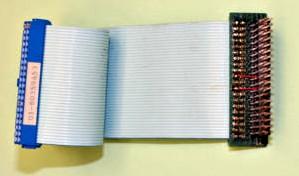
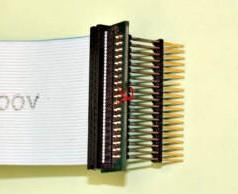
So I decided to make my own. There were two options available to me: I could have added an extension cable to go between the 38-pin command board connector and the control head adapter board (like Motorola's cable), but that would have left the adapter board in the way of much of the control head circuitry. Instead I built an extension cable to go between the control head and its adapter board. This gives me maximum accessibility to all of the rear of the control head. 30-pin connectors won't fit. 26-pin connectors won't fit. No one makes 28-pin connectors. I shall have to adapt.
The Mating Ends:
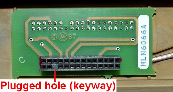
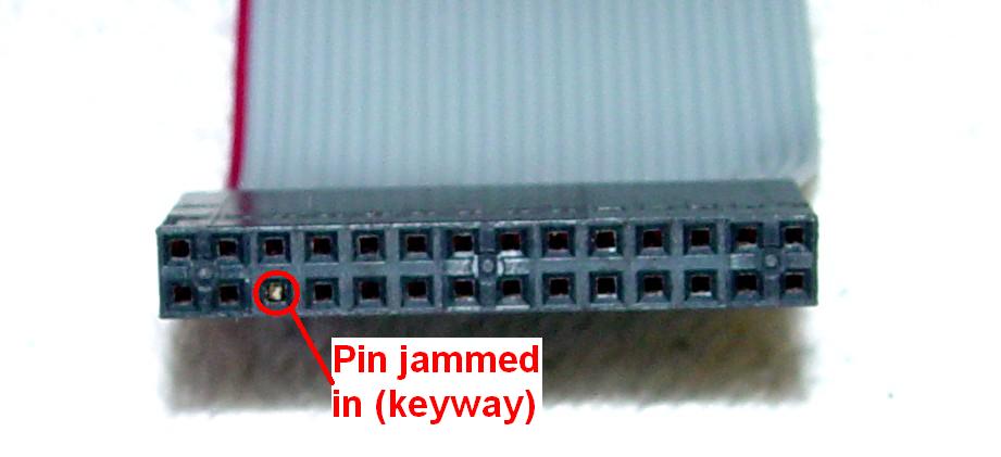
The adapter board goes between the control head and the command board. Here's the female connector the control head has to mate with:
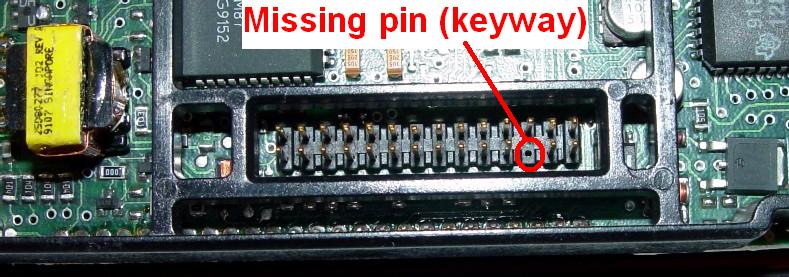
Here's the male connector on the back of the control head circuit board. Note that the plastic board stiffener surrounds the connector, limiting the size of the mating connector.
My Cable:
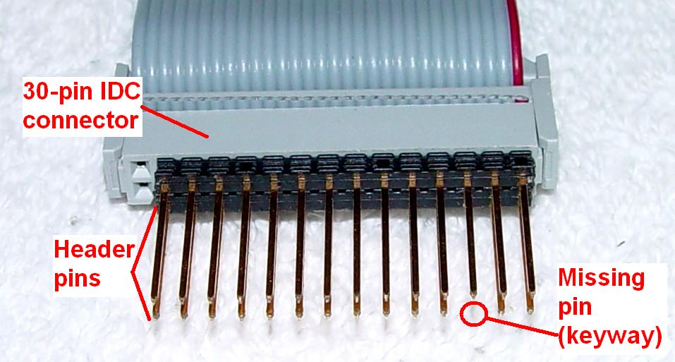
The end that plugs into the existing adapter board needs to be a 28-pin, two-row, IDC-type male cable connector. These do not exist. So instead, I used a standard 3M 30-pin, two-row, IDC-type female cable connector with a piece of a two-row male pin header, which I cut down to leave just 28 pins. I plugged this into the IDC connector then cut off AND SAVED the appropriate keyway pin. I used about a foot of standard flat IDC cable cut down to 30 conductors. I crimped the IDC female connector on one end, matching the red stripe with the pin-1 indicating arrow. This end is shown in the photo below. It mates with the control head socket on the adapter board that plugs into the command board. It's composed of two parts: the 30-pin IDC connector and the 28-pin header strip.
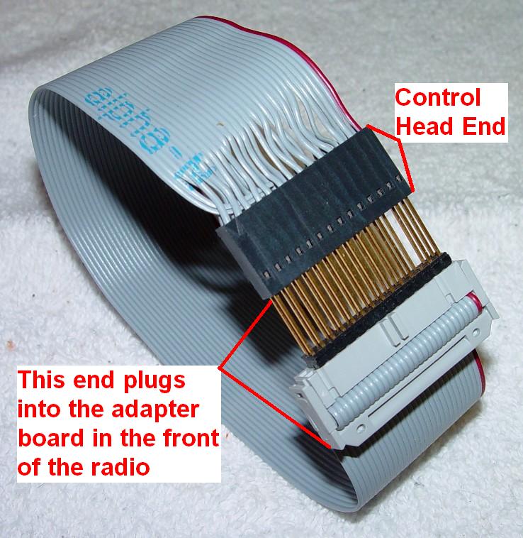
The control head end was a bit more difficult as I really could only fit a 28-pin connector into the space left for the adapter board's socket. So I used a standard AMP 28-pin, two-row female connector with separate solder/crimp contacts. This meant stripping 28 of the 30 wires on the IDC cable, twisting the strands, tinning them, then crimping a female contact onto each one. This was most time-consuming. After that, I checked and double checked the orientation, and started stuffing all 28 contacts into the connector body. This involved alternating the positions of the wires so they'd be in the proper orientation. I tested the first few wires with an ohmmeter to make sure they were being inserted correctly. You want the top row of pins at the adapter board to end up at the top row of contacts on the end that plugs into the control head, so if the cable is laid flat, everything lines up and extends properly. Remember that cut pin from the header? I inserted it into the proper hole to key the connector so it could only be installed one way. Here's a photo of the control-head end of the cable.
The ends of the cable can be plugged into each other when it's assembled properly.
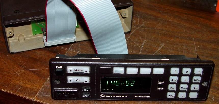
Here's a photo of the cable in use on a VHF radio. Disconnect the power first, then remove the two screws, unplug the control head, plug the cable into the radio, plug the cable into the control head, and fire it up. You can take the plastic housing and front panel off if you need to dig deeper.
Parts:
I started working on this project in late 2006 and made the cable in mid 2008. The prices have gone up by quite a bit since then.
The short end of the header strip gets plugged into the female IDC connector, leaving the longer end to plug into the radio's adapter board socket. You could use a couple of drops of glue to hold the header strip to the connector but I didn't bother.
The total cost is about $20 and it might take an hour to make it, but if you can fix a few otherwise dead control heads, it's well worth it.
Contact Information:
The author can be contacted at: his-callsign [ at ] comcast [ dot ] net.
Back to the top of the page
Up one level (Spectra index)
Up two levels (Moto index)
Back to Home
This page originally posted 06-Mar-11.
Article text, photos, and hand-coded HTML © Copyright 2011 By Robert
W. Meister WA1MIK.
This web page, this web site, the information presented in and on its pages and in these modifications and conversions is © Copyrighted 1995 and (date of last update) by Kevin Custer W3KKC and multiple originating authors. All Rights Reserved, including that of paper and web publication elsewhere.