Up two levels (Moto index)
Back to Home
Dash-Mount Control Head
Interconnect Boards
HLN6066, HLN6285, HLN6268
By Robert W. Meister WA1MIK

|
Up one level (Spectra index) Up two levels (Moto index) Back to Home |
Spectra Low/Mid-Power Dash-Mount Control Head Interconnect Boards HLN6066, HLN6285, HLN6268 By Robert W. Meister WA1MIK |
|
I purchased a Spectra dash-mount 40w range-1 (403-430 MHz) radio, mainly for its A7 control head. The rest of the radio was unimportant. As it turned out, the control head was dead, there was no MLM, and a few hardware pieces were missing. It was a government radio; you take your chances with auctioned equipment and sometimes you lose.
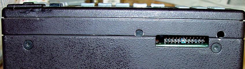
A very nicely machined slot had been cut into the bottom of the front of the chassis, apparently to accept a cable from an external security box. Two captive nuts were inserted into the holes on each side; I've removed them. Here's the slot cut into the chassis:
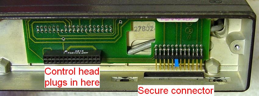
Behind the control head was an HLN6268A interconnect board that took up most of the area behind the control head. Here's an inside view showing the board and the slot:
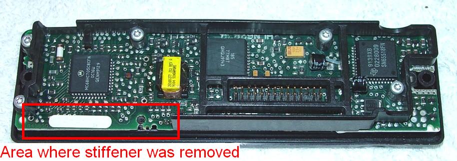
The secure connector on this board interfered with an area of the plastic stiffener on the back of the control head, so part of the stiffener was removed. I surmise this was done at the factory. Due to this interference, a stock A7 control head will not just plug in to the existing interconnect board; I had to take a regular-size interconnect board and plug it in to the front of the radio so a replacement control head could then be plugged in. Here's a photo of the back of the modified control head (yes, the leaky electrolytic capacitors have been changed, but that didn't fix it):
NOTE: It is good practice to consider the interconnect board as part of the control head. If you treat the pair as one assembly, you know it will always plug in to a Spectra radio.
There is a two-pin push-on jumper shorting two pins on the secure connector. I had no idea what this did, and since the radio didn't work anyway, I had no need to try to figure it out. I did determine that a working control head, without its plastic stiffener, plus this 6268A board, would work in a functioning radio, so that jumper was probably important.
I could not find any wiring diagram for either the HLN6268A board or anything that might plug in to the extra 24-pin connector. I also had this burning desire to turn this board into a smaller unit that could be used with any stock control head. To do that, I needed to know what would be missing if I cut off the extra connector and circuit board.
I first tried to visually trace the various interconnections, but this proved impossible, so I grabbed my nearest ohmmeter and started measuring every pin. The table below summarizes the results. The other interconnect board pin numbers were obtained from Spectra basic service manuals: the info for the 6066 board came from a 900 MHz manual; the info for the 6285 board came from a UHF manual. "C H Pin" stands for Control Head Pin and refers to the 28-pin sockets on the front of the board. "Secure Pin" refers to the 24-pin security connector (header) that is accessed through the slot in the bottom of the radio.
| Command Board | HLN6066 | HLN6285 | HLN6268A | ||
|---|---|---|---|---|---|
| Pin | Signal Name | C H Pin | C H Pin | C H Pin | Secure Pin |
| 01 | +9.6V | ||||
| 02 | A3 Volume | 28 | |||
| 03 | Emergency | 28 | |||
| 04 | Channel Active | ||||
| 05 | Filtered Audio | ||||
| 06 | Microphone High | 27 | 27 | Note [1] | 06 |
| 07 | Ground | 03 | 03 | 03 | 05,20 |
| 08 | Receive Audio | 09 | |||
| 09 | Busy | 25 | 25 | 25 | 13 |
| 10 | Ground | 24 | 06,13,24 | Note [2] | |
| 11 | Reset | 23 | 23 | 23 | 10 |
| 12 | Transmit Audio | 08 | |||
| 13 | Detected Audio | 07 | |||
| 14 | Spare 1 | 08 | 08 | 08 | |
| 15 | SecureNet | 21 | 21 | ||
| 16 | SecureNet | 20 | 20 | ||
| 17 | VIP Out 2 | 19 | 19 | 19 | |
| 18 | VIP Out 1 | 18 | 19 | 18 | |
| 19 | Data | ||||
| 20 | Transmit Data | ||||
| 21 | Ignition | 11 | 11 | 11 | |
| 22 | Bus - | 10 | 10 | 10 | 11 |
| 23 | SecureNet | 09 | 09 | ||
| 24 | PTT | ||||
| 25 | Bus + | 22 | 22 | 22 | 12 |
| 26 | Data | ||||
| 27 | Spare 2 | 07 | 07 | 07 | |
| 28 | Ground | 06 | 06 | 06,13,24 | Note [2] |
| 29 | A3 Data In | ||||
| 30 | A+ | 05 | 05 | 05 | 03 |
| 31 | SWB+ | 04 | 04 | 04 | 04 |
| 32 | KEYWAY | ||||
| 33 | Clock | ||||
| 34 | Speaker Lo | 02 | |||
| 35 | Speaker Hi | 01 | |||
| 36 | UNSW 5V | ||||
| 37 | +5V | ||||
| 38 | VAG | ||||
Yes, there ARE differences and discrepancies. Some are due to revisions in design of the Spectra products, others are just the result of poor editing. Two things you can count on: errors in Motorola manuals, and good Motorola products that are NLA (No Longer Available).
The control head and secure connectors are along the bottom edge of the front of the board; that's the side that the control head plugs into. This is a photo of the front of the board, looking into the front of the radio after removing the control head:
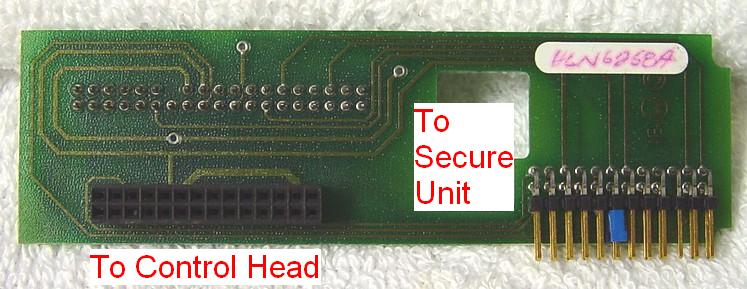
This is a photo from the rear of the 6268A board. The connector on the left is the right-angle header that the security box plugs into. I arbitrarily numbered the pins in the same order as on the control head connector, as I had nothing else to refer to. There is a small capacitor soldered across the secure connector from pin 09 to pin 16.
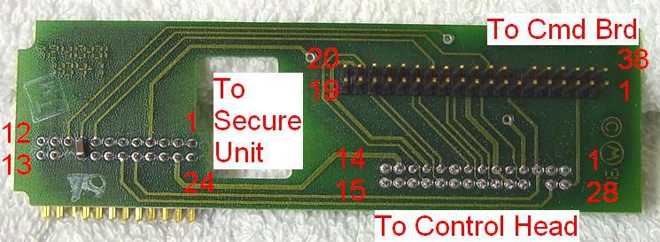
The long pins on the rear of the board, that plug into the command board, are numbered as shown below. This is when viewing the board from the rear, with the pins facing you:
| 20 | 21 | 22 | 23 | 24 | 25 | 26 | 27 | 28 | 29 | 30 | 31 | -- | 33 | 34 | 35 | 36 | 37 | 38 |
| 19 | 18 | 17 | 16 | 15 | 14 | 13 | 12 | 11 | 10 | 09 | 08 | 07 | 06 | 05 | 04 | 03 | 02 | 01 |
This information was obtained from several Spectra Basic service manuals plus the Spectra Detailed service manual, all copyrighted by Motorola. Physical examination and actual tracing of the connections was necessary for the secure board.
Mike K7IC offered the following historical information about this connector and what plugged into it. This section, the links, and the information they refer to, are all copyright by him.
My background information on this is:
http://www.onfreq.com/syntorx/spectra/partssp.html#sprdib
HLN6268A - Secure, Low Power, Dash Mount, P103, Physical Security Housing (plugs in underneath radio, see note below)
Note: There is a connector access hole cut into a special version of the main Spectra radio chassis to allow the HKN6044A Securenet cable to attach to the HLN6268A Interconnect Board. The dash mount HLN6268A Interconnect Board requires this special Spectra radio chassis (part number 2780246R01).
Here is the control head P103 pin out info (it depends on the control head version):
http://www.onfreq.com/syntorx/spectra/boards.html#chp103
http://www.onfreq.com/syntorx/spectra/boardvar.htmlI do not have the pin out info for the HLN6268A securenet connector.
HKN6044A - Cable, Dash Mount Radio, Physical Security Housing to underside of 2780246R01 Radio chassis (No Longer Available)
Since it has a special chassis, all you can do is connect the HKN6044 cable, block the hole off, or leave it gaping open.
This is the only dash mount Spectra configuration I'm aware of that supported the external physical security housing encryption units. All the other securenet dash mounts use the internal encryption boards. Except for this one configuration, the physical security housing encryption is used in a remote mount with the detached control head.
If I remember correctly, only the external physical housing securenet offered advanced features like OTAR (Over The Air Re-keying), government Fascinator encryption, hidden tamper erase switches, etc. This made them different from the internal full featured securenet, which is probably why Motorola did not drop the external physical housing all together and went on to develop a dash mount that could use the old external housings.
The HLN6066 interconnect board is an older board with special connection considerations when used with newer control heads.
http://www.onfreq.com/syntorx/spectra/index.html#spifix
Your HLN6258A has more in common with the newer HLN6285 interconnect boards. This means it will work with old or new control heads as is with your jumper modifications.
A more slightly complete pin out of the P502 connector is here (it shows pin labels with multiple uses between different versions of the command board, except it does not show SP boards):
http://www.onfreq.com/syntorx/spectra/boards.html#spp502
This link is a diagram with all the control head part numbers (as noted above in the modification, some heads require specific or modified interconnect boards). The diagram has hot links you can click on for more information like this one:
http://www.onfreq.com/syntorx/spectra/index.html#combo
http://www.onfreq.com/syntorx/spectra/partssp.html#spcheaThe reason the older HLN6066 interconnect board has emergency and speaker connections is the very first remote mount was made by installing the HLN6066 dash mount interconnect board with a HLN6055 remote mount interconnect board on top of the 6066. The HLN6055 was replaced long ago with the now familiar dedicated remote mount interconnect boards that did not require a second interconnect board. A true dash mount only board does not need the speaker or emergency lines (the rear J2 DA-15 connector emergency and speaker pins were used instead). Some of the discrepancies you noticed in the documentation actually had a reason for existing ("had" as in past tense). The HLN6066 is not a very good comparison for the HLN6268 since they are basically dissimilar. However, the HLN6285 is a good comparison.
As long as you are not using any of the old HLN6055 boards or SP radios, your HLN6268 board and the HLN6285 are replacements for the HLN6066 in the old and new radios and work with the old or new control heads too.
All photographs were taken by the author.
The author can be contacted at: his-callsign [ at ] comcast [ dot ] net.
Back to the top of the page
Up one level (Spectra index)
Up two levels (Moto index)
Back to Home
This page originally posted 17-Oct-2007.
Article text, photographs and hand-coded HTML © Copyright 2007 By Robert W. Meister WA1MIK.
This web page, this web site, the information presented in and on its pages and in these modifications and conversions is © Copyrighted 1995 and (date of last update) by Kevin Custer W3KKC and multiple originating authors. All Rights Reserved, including that of paper and web publication elsewhere.