Up two levels (Moto index)
Back to Home
By Robert W. Meister WA1MIK
|
Up one level (Spectra index) Up two levels (Moto index) Back to Home |
Spectra Low/Medium Power DC Power and Ignition Cable By Robert W. Meister WA1MIK |
|
How This All Started:
I bought a UHF Spectra dash-mount radio to replace a similar MaxTrac radio in my truck. I don't use or need ignition control, but the Spectra needs +12V on the ignition control lead of the DA-15 accessory jack in order for the radio to operate. I just wanted this to be a plug-and-play replacement without running another wire under the dash.
The Spectra didn't come with any accessories. I had a spare microphone and speaker, and I decided to buy and make my own DA-15 accessory cable. I gave the whole project some thought and came up with this unique solution to several problems.
Background:
The Spectra low- and medium-power mobile radios come in front (dash) mount, and trunk (remote) mount models. All of these radios use an external loudspeaker that is cabled to the accessory jack (in the case of dash mount) or to the control head (in the case of remote mount). They use the same two-pin DC power connector that's used on MaxTracs, GM300s, GTXs, and several other Motorola mobile radios. Unfortunately, Spectras also require a second source of DC to operate the ignition control input. Typically this wire is connected to a circuit in the vehicle that is only powered when the ignition key is in the ON or ACC position. This way, the radio will be shut off when the vehicle is turned off. MaxTracs (and the other models mentioned above) by default do not utilize ignition control, but you can wire the radio to operate that way if you want.
Several people had suggested adding a jumper to the command board inside the radio, to supply power to the ignition control line, thereby eliminating the need for an ignition control voltage at the accessory connector. This requires removal of the command board to get to the proper points which are located on its bottom surface. This board is central to the entire operation of the radio, and several other assemblies need to be removed to get the board out. I had dismissed this idea quite early, opting for a less permanent, external method of getting the radio to operate.
Another problem with adding a jumper inside the radio is that the next unsuspecting owner might supply power via the primary DC input and find out that the ignition control lead is now feeding power back out to other accessories in the car. I'd rather not risk the chance of injury to myself or the vehicle.
What I needed was a pair of DC power connectors with a few inches of wire between them, so I could tap into the positive lead and feed that to the ignition control lead. I have not found a source of bare unwired DC power connectors; all the ones available have molded wires already attached. So I used what was available.
My Solution:
Since I couldn't make my own DC power cable from scratch, I decided to splice the ignition control line to a pre-made cable. This gives me a short pigtail hanging off the back of the Spectra radio that has the accessory plug permanently attached.
I bought a DC power cable, a 1A AGC fuse, and an AGC fuse-holder from Tower Electronics.
I bought the DA-15 male connector, Spectra-compatible hood, Molex commercial MATE-N-LOK connectors and socket pins, from Mouser Electronics.
Parts List:
Prices are for each component as of June 2006.
| Description | Part Number | Price | Source |
|---|---|---|---|
| 2-pin DC disconnect, 10-gauge, 1 foot | Use description | $2.00 | Tower |
| Inline AGC fuse holder, 14-gauge | Use description | $1.00 | Tower |
| AGC 250 VAC / 32 VDC fuse, 1 Amp | Use description | $0.10 | Tower |
| DA-15 male plug | 156-1215 | $0.65 | Mouser |
| DA-15 plastic hood | 152-6015 | $1.86 | Mouser |
| AMP commercial 2-ckt socket housing | 571-14803180 | $0.13 | Mouser |
| AMP connector sockets, 24-18, QTY 2 | 571-606171 | $0.10 | Mouser |
The matching loudspeaker connector components are shown below. I needed them because my speaker was made for another radio model and it had the wrong connector on the end of the cable. These were bought at Mouser along with the other parts:
AMP commercial 2-ckt pin housing, 571-14803190, $0.13
AMP connector pins, 24-18, QTY 2, 571-606181, $0.14
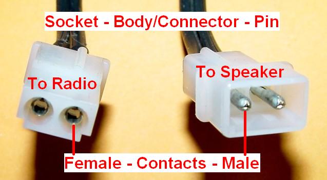
Note that the ignition cable has the AMP socket housing with female sockets. This fits inside the pin housing that's on the wire coming from the loudspeaker. The connector part naming is confusing, so here's a photo showing the orientation:
Construction:
The Molex socket pins got crimped and soldered to the end of about 8 inches of spare 18-gauge speaker wire. These were then snapped into the plug body. The other end of this wire was passed through the DA-15 hood.
The fuse-holder wire was cut in the middle. One end was passed through the DA-15 hood.
I wired the DA-15 male connector as follows:
Solid wire jumper (emergency control) from pin 2 to pin 8.
Ignition control wire from fuse-holder (through DA-15 hood) to pin 5.
Loudspeaker wires with Molex connector (through DA-15 hood) to pins 6 and 7.
I split the insulation in the middle of the red wire of the DC power cable and soldered the free end of the fuse-holder to the exposed conductor. I taped the connection and secured the wires with a nylon tie.
This cable can be plugged into the radio in either direction. You want to make sure the end of the red wire with the insulated terminal mates with the bare terminal on the radio. The end of the red wire with the bare terminal mates with the existing power cable in the vehicle. You can connect them the other way; no damage will occur but the radio will not see +12V on the ignition control wire and will not power up. Just be careful when you plug things in. You might consider putting a label on one end if someone else will ever work on this setup.
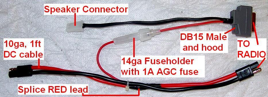
Here's the completed cable. The radio would be on the right side of this photo. Click on the photo to enlarge it.
Here's how things fit together in a typical installation. The DA-15 plug fits into the accessory jack on the back of the radio. The big power cable plugs into the DC input jack on the back of the radio. The loudspeaker plugs into the 2-pin Molex connector. Click on the photo to enlarge it.
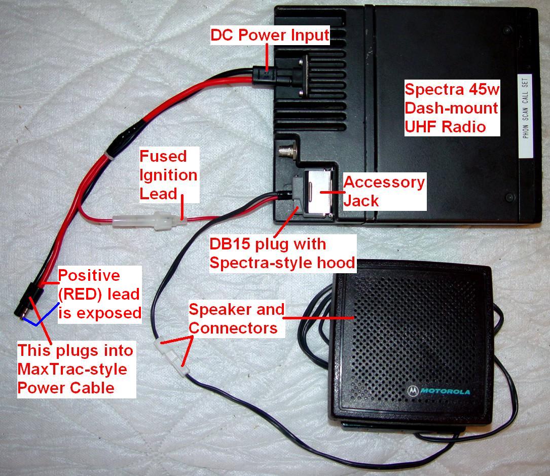
The free-hanging end of the DC power cable would connect to the mating cable that's already powering my MaxTrac radio.
Simple, elegant, and quite inexpensive.
Contact Information:
The author can be contacted at: his-callsign [ at ] comcast [ dot ] net.
Back to the top of this page
Up one level (Spectra index)
Up two levels (Motorola index)
Back to Home
This web page, this web site, and the information presented in and on its pages is © Copyrighted 1995 and (date of last update) by Kevin Custer W3KKC and multiple originating authors.