Up two levels (Moto index)
Go to the Home page
By Robert W. Meister WA1MIK
|
Up one level (Spectra index) Up two levels (Moto index) Go to the Home page |
Miscellaneous Spectra Topics By Robert W. Meister WA1MIK |
|
This is a collection of little tidbits I've discovered while working with my 900 MHz 30 watt Spectra dash-mount mobile radio (ID # D37KGA5JE7AK, Model # DE7KG+110W), as well as my 450 MHz 40 watt Spectra trunk-mount A9 (soon to be a dash-mount A7) mobile radio (ID # T44KXA7JA9AK, Model # TA9KX+068W), and a rather old VHF 50 watt dash-mount mobile radio (Model # D43KMA7JA7BK). If anyone has implemented some of these tips on other model Spectras, please send feedback to the author.
Deleting Trunking Modes:
To do anything with trunking personalities, systems, or modes, you'll need system key files; these are typically put into a SYSKEY folder and the RSS reads these when it starts up. Each system ID needs its own key file which has that system ID encoded within it. Make sure the PC configuration path (main menu, F9) points to the SYSKEY folder.
To get rid of your extra trunking modes, here's what you need to do:
One person reported that if you read the radio again, the RSS may revert to the default 15 systems, 16 sub-fleets, 10 conventional setup and you'll need to go back into F2 - Radio-Wide and reset everything. I did NOT have this happen to me; the values remained at 1/1/128.
Removing That Last Trunking Mode:
There are two ways to do it. The first way is to convert the radio to conventional only, but this is way over most people's heads and requires a lot of knowledge.
The second way will not remove the trunking features but it will get rid of that
last annoying trunking mode every time you scroll through your channels. You must first
delete all the trunking personalities and modes except for one; this was described
above. As you have found out, every time you attempt to delete that last one, RSS won't
let you.
Write the code plug to the radio. When it reboots, you will get an ER 01/02 or an ER 01/82, depending on the radio. The manual says this means there's a problem with the data in the EEPROM (i.e. the code plug) that the radio is not happy with. You could live with it, but it's not pretty to see every time the radio turns on. To get rid of it completely, read the code plug from the radio once more, then immediately write it back to the radio. The radio will now reboot cleanly with no more annoying trunking modes.
Regarding changing the number of system, subfleets, and conventional modes, the programming manual has this to say:
"These parameters control how the program allocates the mode within the radio. When adding trunking systems or subfleets, or conventional modes, these limits cannot be exceeded.
With some radio models, these parameters can be changed by the program user. This may be used to trade off fewer trunking subfleets for more conventional modes, for instance. [ NOTE added by author: this implies that some radio models unfortunately will NOT let you alter these fields. It seems that B5 radios, in particular, won't let you access these fields on the left side of the screen. ]
Use the UP/DOWN arrow keys to change these fields. The maximum number of modes any radio can contain is 250. Therefore the program will never allow MAX SYSTEMS multiplied by MAX SUBFLEETS and then added to MAX CONV MODES to exceed 250.
IMPORTANT: The limits shown on this screen do not necessarily represent what the radio can be programmed with in all instances. If the radio is programmed beyond the limits shown in the catalog sheet for that model it is possible to create a code plug that will not fit in the radio.
The code plug 'space' each mode, personality, or system uses can vary depending on the number of options enabled. The program stores information into the radio as efficiently as possible, therefore there is some variation in code plug size requirements even if the number of modes remains the same. This flexibility can be very useful, however it may also be confusing because code plugs can be created that will not fit into the radio. If a code plug does not fit into the radio an error will be given when trying to save it to the radio or to an archive. At that point, modes, personalities, or features must be disabled before the code plug can be stored. Features that take up large amounts of code plug space include: mode slaved scan, system search and lock, and private call/call alert lists."
Emergency Signaling:
If you have an Emergency button on your control head, and have activated the emergency MDC signaling in RSS, be careful about unplugging the radio. If you remove the accessory cable that normally has an emergency jumper in it, the radio will silently power up and transmit the emergency MDC code without showing anything on the control head.
Once triggered, you can cancel an emergency transmit condition by pressing and releasing the microphone's PTT button, or by turning the radio off then on. It won't stop transmitting if you just turn the radio off - you must cycle the power completely. Of course, you can still pull the main DC power cable to shut it down.
Always unplug the main DC power cable before you disconnect the accessory connector. Plug the accessory connector in before the main power. Also take this same precaution if you unplug the accessory connector to subsequently program the radio.
This actually happened one afternoon to another ham. He had just finished making a programming cable, and decided to test it out. He removed the accessory plug from the radio, which contains the emergency switch jumper. The radio immediately started transmitting its emergency MDC code on the last channel it was set to - that of the local repeater. It kept doing this until something was plugged back into the accessory jack and the radio was turned on. Because there's no indication on the display that anything is happening, this occurred several times. Two hours later, I heard my friend sign onto the repeater. I mentioned the MDC I heard earlier and my friend sheepishly realized what he had done and apologized. The moral of the story: unplug the main DC power cable before you remove any accessory plug from the radio.
Receiver Sensitivity vs Squelch Settings:
The following data was obtained using a Spectra 900 MHz radio programmed to receive 927.50000 MHz and a Spectra 450 MHz radio programmed to receive 460.5000 MHz. A calibrated signal generator was connected directly to the radio's antenna jack.
In this table, Val is the value displayed on the control head when setting the squelch using the Mode Up/Dn buttons, 150.0 is the signal level in microvolts required to break squelch and keep it open on the VHF radio, 460.5 is the signal level in microvolts required to break squelch and keep it open on the 450 MHz radio, and 927.5 is the signal level in microvolts required to break squelch and keep it open on the 900 MHz radio. There is some hysteresis between the squelch open and closed points; this means that once the squelch opens, it will take significantly less signal to let it close. I only recorded the points where the squelch opened as the signal increased.
|
Front panel RSSI values on a 450 MHz radio go from about 35 to 116, and about 30 to 110 on a 900 MHz radio. Some radios can go higher. The following data was measured at the indicated frequency in MHz. The numbers in these two columns are the RSSI value displayed on the front panel. The last RSSI value of 110 is extrapolated, as the maximum value on my radio was 108.
|
Unpowered Programming Cable Syndrome:
If you plug a programming cable into a low/medium power Spectra, and the RIB is attached but not powered up, the radio may do all sorts of strange things, like turn on and off and display some error codes, when you turn it on. You'll think you have some bad connections. The unpowered RIB loads down the BUSY and BUS lines and confuses the radio.
The solution is to apply power to the RIB before attaching it to the radio or turning the radio on. My after-market RIB does not have a way of being powered from the radio; it can only run from its own 9V battery. Some after-market RIBs and the real Motorola RIB (RLN-4008) will get power from the Spectra's SWB+ line, if that wire is present in the radio-to-RIB cable.
Note that an unpowered RIB will also cause many mobile trunking radios to power up in a test mode.
Enabling Control Head DTMF Transmission:
With an x7 or x9 control head (ones with the 12-button keypad array on the right), DTMF transmission is possible using the 12-button section of the control head. Each mode must have DTMF enabled and there must be a "PHON" button enabled on the control head. Pressing this button puts the radio into DTMF mode. The MODE rocker button now scrolls the display through several settings:
Other Useful Signal Levels:
The Ignition Control input line draws about 1mA DC whether the radio is on or off.
Spectra radios draw about 20-25mA DC when turned off. This is the keep-alive power for things like the operator-selected scan, last mode, volume, etc. Spectra radios will also lose these settings if the voltage on the main power cable falls below 6 volts for more than 15 to 30 seconds (i.e. during hard starting of the vehicle).
At the speaker terminals, with no speaker attached, the DC voltage is 0.4V on each terminal when the radio is squelched, 6.14V when unsquelched. This can be used as a COR (carrier-operated relay) signal. DO NOT ground either speaker line - both lines are driven (in push-pull) by the radio's audio amplifier.
Using a 0dBm RF signal modulated with 400 Hz tone deviating at 1 kHz, the volume was adjusted for 0dBm (0.775VAC) as a convenient reference level at the speaker terminals with no speaker attached. With no modulation, the noise measured -44dBm. At a signal level of 0.376uV, the noise measured -20dBm; this is the 20dB quieting signal point. The spec is 0.40uV for 20dBq and 0.30uV for 12dB SINAD. When the radio was squelched and had no input signal, the audio voltage was -77dBm at the speaker terminals.
The Flat/Raw RX audio output on the accessory jack of a 450-480 MHz radio has a sensitivity of 0.21VRMS per 1 kHz of incoming audio deviation, and this is very linear (1.05V=5kHz). It is flat (within plus or minus 0.5dB) from 50 Hz to just over 3 kHz, then it starts dropping off, reaching about 3dB down at 4 kHz.
The MIC audio input on the accessory jack of a 450-480 MHz radio follows the standard 6dB per octave rise (pre-emphasis). Using a 400 Hz sine wave, this input requires 70mVRMS to produce 1 kHz deviation, and this is very linear (240mV=3kHz). With a 2000 Hz tone, it requires 15mVRMS to produce 1 kHz deviation, and it is similarly linear (45mV=3kHz). The radio goes into limiting over 3.5 kHz sine wave deviation; voice peaks will reach 5 kHz deviation.
Changing a Trunk-mount A9 Radio to a Dash-mount A7 Radio:
I acquired a UHF trunk-mount radio without any accessories or the A9 control head the radio originally came with. (The A9 control head is also called the System9000 or S9000 head. It is much larger than a dash-mount control head, is only available with trunk-mount radios, and can display 11 characters across the display.) I removed the original front panel from the radio and put an A7 control head on in its place, attached a speaker and power cables, and turned it on. The display worked, the speaker worked, the Dim, Home, Mode, and Volume controls worked. The radio transmitted and received, but none of the other buttons worked. I tried reading the radio's code plug with RSS but got an error about a missing S9000 control head (the A9 head the radio was configured for). Without that, RSS refused to go any further.
It seems that RSS stores the mode names in the control head memory on radios that are configured for an A9 control head, and it was unable to read those names because that control head was no longer attached. Unfortunately, I didn't have an A9 control head lying around to attach to the radio at this point. If I did, I could have read the code plug, changed the control head type from extended (A9) to standard (A7) and been done with it.
Using information found elsewhere on the web, I used the bit-banger utility in Spectra LAB RSS to change location 6060 (hex) from CD (hex value for the A9 control head) to ED (hex value for the A7 control head). When I exited the RSS service mode, the radio rebooted and gave me an "FL 01/82" error; this means an internal checksum is incorrect. The standard fix for this condition is to read the code plug with standard RSS and immediately write it back to the radio (from the main menu, press F3, F2, F8, F8). After this, the radio passed its internal self-checks and worked just fine with the A7 control head, except that the mode names on the display contained gibberish characters.
I read the code plug again, edited the mode names to something that made sense, then assigned functions to the various pushbuttons on the A7 control head, since they were all set to BLANK. Once this was done, all the labeled functions worked perfectly.
Other values that can be put into location 6060 for different control heads are: A4 head (hex BF), A5 head (hex AF). This same technique also works to convert a radio that had an A5 head to accept and operate with an A7 head.
Changing an A7 radio to an A9 Radio:
This information was provided by Jay, K2JSV: Hook everything up as an A9. Go in, bit-bang the model number strings and the control head type byte to indicate an A9 control head is attached (see the section above for the location and values). Then, you will be able to read the radio and control head as an A9 without any troubles. Worked every time for me without fail.
Other Control-head-related Information:
When swapping dash-mount control heads, such as putting an A7 head on a radio that previously had an A5 head, think of the interconnection board - that plugs into the back of the control head - as an integral part of the control head. In other words, keep the board with the head and swap both as one assembly. The connector and signals on the command board are identical in all radios, but the control head uses the interconnect board to deal with feature, wiring, and revision differences.
There are several different interconnection boards. I found one that worked fine with some older A5 and A7 heads, but would not work with a newer A5 head. The radio would power up always transmitting. This can be fixed if you modify the interconnect board, but in my case it was easier to put on an older head.
The same holds true for remote-mount heads. Swap the head and whatever interconnection board is attached to it as one unit. The head end of the cable should be the same on all radios.
When converting between remote-mount and dash-mount radios, keep the interconnect board with whatever plugs into the front of the radio, either the control head or the plate with the DB25 connector(s).
Increasing Transmit Deviation:
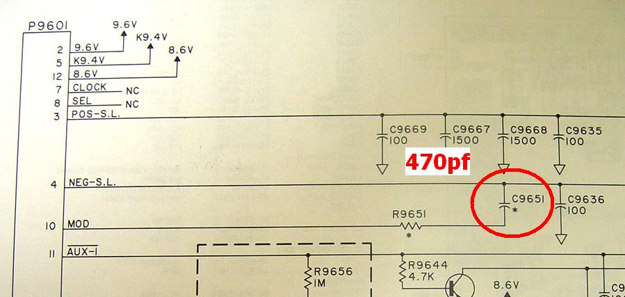
The Spectra 900 MHz radio is rated for +/- 2.5 kHz transmit deviation. This can be increased to more than 5 kHz by adding a 0.001uF capacitor across C651 on the VCO. This is a coupling capacitor that feeds modulation audio to the VCO. It can easily be bridged from the solder side of the VCO, in a manner similar to that used to lower the operating range of the VCO. A photo and schematic segment are shown below.
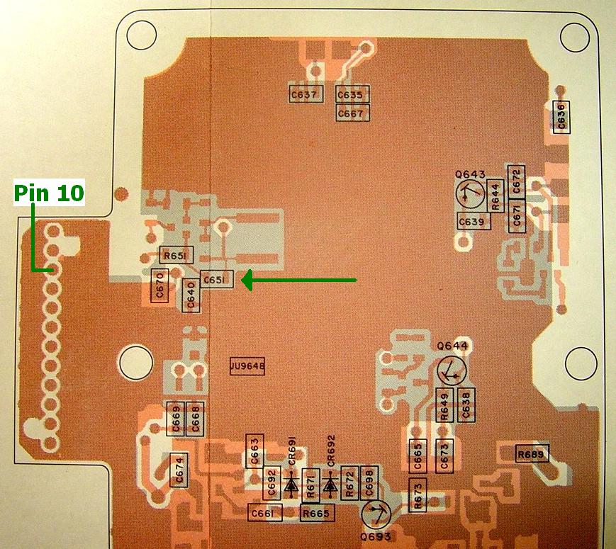
You will still have a narrow-band receiver. You would need to replace the IF filters (the two blue rectangular items in the photo below) and several other components to change to a wide-band receiver. The Spectra radio can not do 2.5 kHz on one channel and 5 kHz on another; there's no circuitry or code plug setting to change this.
An alternative has been discovered. There's a byte in the radio's memory at hex location 605F that tells the radio and the software what bandsplit the radio is operating on. Stock 900 MHz radios have "E7" as their range value. It seems that the most significant bit (hex 80) when ON sets the radio for 2.5 kHz operation, and when OFF sets the radio for 5 kHz operation. This has been verified on multiple radios and multiple bands (VHF, UHF, and 900 MHz). When the bandsplit value was changed from "62" to "E2" on a VHF radio, the transmit deviation was reduced from 4.7 kHz to 2.35 kHz. Similarly, the recovered audio (at one particular volume control setting) increased from 426 mV to 852 mV. Likewise, when the bandsplit value was changed from "E7" to "67" on a 900 MHz radio, the transmit deviation increased from 2.7 kHz to 5.4 kHz and the recovered audio decreased from 520 mV to 260 mV. The squelch also opened under this condition, because there wasn't enough high-frequency noise amplitude coming into the squelch circuit as compared to the narrow-band operation. Thanks go to Alex K6LPG for bringing this to my attention.
Note that this narrow/wide selection only affects the audio levels. The modulation acceptance of the receiver is dictated by the crystal filters on the RF board; that cannot be changed through software or any hex-editing. But for those areas that have 5 kHz repeaters on 900 MHz, this is an easy way to make the radio work a bit better for those users that need it. This change affects the entire radio; it's either wide or narrow.
You need to use Spectra lab software's bit-banger utility to change this byte. As with all hex-editing sessions, after changing any data bytes, the radio reboots with the dreaded "FL 01/82" error and you need to recover from that by reading the radio's code plug then immediately writing it back to the radio.
TP603 on the RF board:
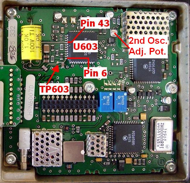
The basic service manual outlines two procedures for adjusting the VCO and/or deviation compensation circuitry. One paragraph mentions measuring a signal on TP603. This is a "guard ring" that connects U603 pin 43 to pin 6, and it circles around several sensitive components. I suspect the adjustment reduces noise in this area. TP603 is a small, unmarked solder pad on this ring, near U603 pin 6. It is shown in the photo below on a 900 MHz RF board. Note also that C636 near the top of the board, above U603, is not installed (see the Spectra Time-Bomb Capacitors article for more details).
Intermittent Dead Receiver:
A friend's UHF Spectra arrived with a dead receiver. It wouldn't hear a thing on my bench, but would work once in a while on my friend's bench. The front-end and VCO were working; we measured the 1st oscillator injection (VCO output) at 554.1 MHz with the radio set to receive 444.45 MHz, and the mixer output was 109.65 MHz. We could pick up the 2nd oscillator on the RF board (with the shielding removed) at 109.3 MHz.
Unfortunately, the 2nd oscillator is supposed to run at 109.2 MHz. It is a free-running oscillator that's controlled by a phase-locked loop (PLL) circuit. It is adjustable via the only potentiometer in the entire radio, which is located on the RF board. It is labeled in the photo above.
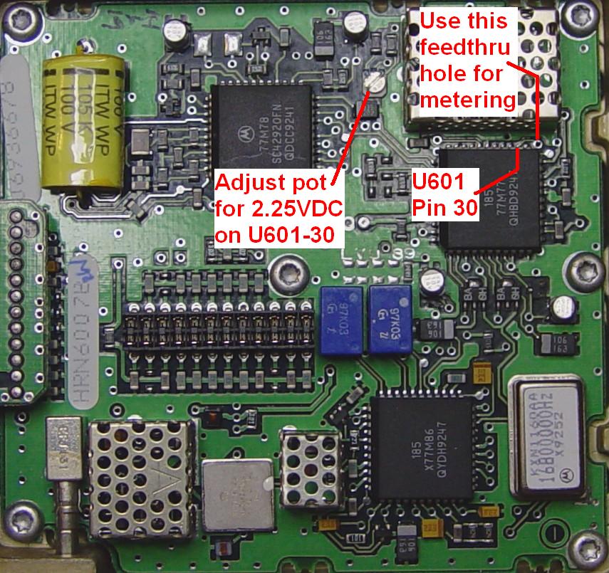
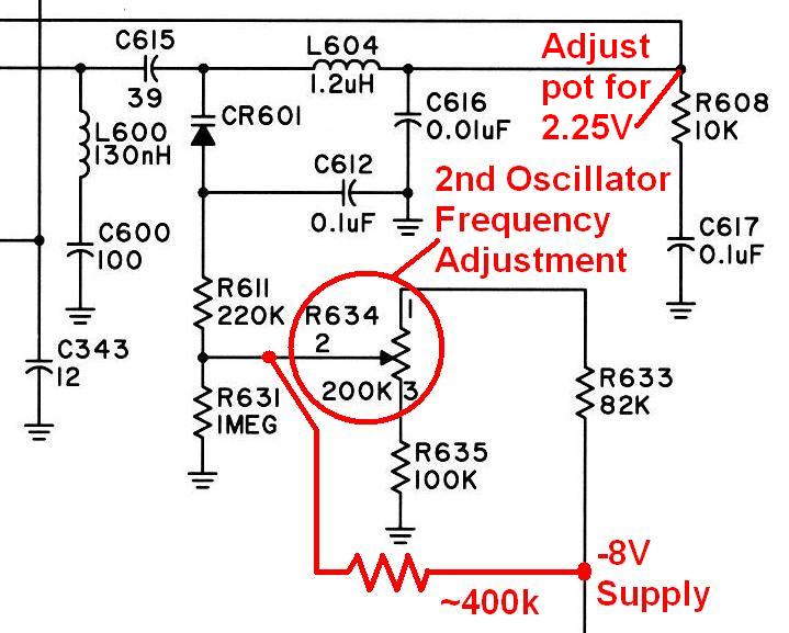
The basic and detailed service manuals mention the 2nd oscillator's control voltage, but do not give a procedure or measurement point for adjusting it. All they say is that the pot is "adjusted at board test for 2.25 volts at the phase detector output" and go on to other subjects. The phase detector output is U601 pin 30, which runs to the junction of R608 and L604. These components are located under the perforated shield that covers the 2nd oscillator, directly above U601 in the photo below. You can still access U601 pin 30 at a very convenient feedthru hole. The exact voltage doesn't seem to be critical; the radios I checked had 2-3VDC present at that point. See the photo below.
At the time I didn't realize this, so I measured -3.63 volts on the arm of this pot on my working UHF Spectra at that tiny feed-through hole above the upper-right corner of the pot. On my friend's radio, that voltage was varying anywhere from -1.9V to -6.0V, so the oscillator was picking any frequency it wanted. Occasionally it would settle down at 109.2 MHz and we would hear the incoming signal; most of the time it wouldn't.
Touching this pot with a tuning tool would cause the voltage on the arm to vary wildly. However when it was around -4V, the radio would hear input signals just fine.
The pot was carefully removed and it fell apart into several pieces. Apparently the ceramic had cracked, the arm of the pot was loose, and the entire component was unreliable. No wonder the 2nd oscillator was off-frequency. Nothing else in the radio showed evidence of damage, so we don't know if the pot was defective or someone used a "golden screwdriver" on it. A new 200k pot, part number 1880273N01 costs about $2US in mid-2007.
A fixed resistor of about 400k was installed from the -8V supply to the feed-through hole where the arm of the pot was connected. See the schematic diagram below. The control voltage is now around -3.6V and the radio has been working perfectly since that modification. Also, the 2nd oscillator is running at 109.2 MHz (where it should be) and is audible on a nearby receiver.
Fuse on Command Board:
While commonly thought to be an ignition control fuse, the small Pico fuse located near the front of the command board behind J502 is actually there only to protect the audio power amplifier integrated circuit. You can see this shiny olive-drab (green) fuse in the command board photos in the Spectra Interfacing article found here.
There is an ignition control fuse on MaxTracs that is often replaced by a jumper, and this component is removed to activate ignition control on those radios, but NOT on the Spectras.
PL/DPL Not Working:
This seems to be a common complaint, especially after reprogramming the radio.
It seems there are either some improperly modified copies of software roaming around, the version prior to the latest had this as a known bug, or some older radios have a problem. The program accepts out-of-range frequency information, but manages to mess up the coded squelch settings. This can usually be fixed by reading the code plug with a non-modified (stock) program, changing just the coded squelch values, and writing the code plug back to the radio. Of course, this means keeping multiple copies around, and knowing when to use each one.
I also feel that some public hex-editing information causes the user to change more locations than are actually necessary, thus causing the program to work improperly.
The locations and method described in this article produce a program that lets the user change the code plug as desired, without having to go back and forth between a stock and modified program. It does, however, require that an original stock program, as documented in the article, be used as the basis for the modifications.
Audio Power Amplifier IC:
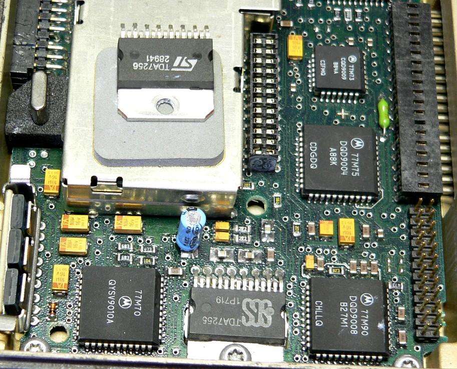
Seems there are radios out there with the TDA7255 and the TDA7256, both 15-pin ICs. The commercially available TDA7256 is an 11-pin IC that obviously can't be directly soldered into the Spectra radio, but both the 15-pin TDA7255 and 15-pin TDA7256 seem to play well in the radio. Jim W8WRP reported that he had a Spectra radio with a dead TDA7256 so he replaced it with a TDA7255 he pulled out from another Spectra radio. As both were 15-pin, they went in easily and worked just fine. His photo below shows the old chip sitting on top of the MLM shield. This is a very old command board.
Variable Transmit Power:
High-power Spectra radios were normally used in situations where the users needed that much power. Whatever power you set the radio for, that's what it will transmit with, on all available operating modes. You can't change it without RSS or going through the control head to access the service menus, and any change affects all modes.
Some radios, notably the E-series 900 MHz mid-power units, can have the transmit and talk-around power set separately to either high or low, on a mode-by-mode basis. You still have to set the high and low power levels with RSS or the control head service menu. Other models may or may not offer this choice. On the Mode screen, press F7 for Other Options and check the fields on the right side of the screen.
There's no way to assign output power level to any control head button. The best you can do is have two identically programmed modes where one is high power and the other is low power, with mode names that reflect that difference.
HearClear / Compander Issues:
900 MHz Spectra radios have fields for Adaptive Splatter Filter and Compander that can be enabled or disabled on a mode-by-mode basis. This Compander is compatible with HearClear, a noise-reduction and voice-enhancement system found on a lot of other Motorola 900 MHz radios. Other manufacturers have a similar and compatible scheme.
The audio level coming out of the speaker on the E-series (also known as Spectra-II) radios seems to be about 10 times louder on Compander-enabled modes than on modes with it disabled. That's a significant difference. Regular Spectras have much more balanced speaker audio levels. The command board for the E-series radios is quite a bit different from the regular command board. On 900 MHz, the HearClear chip is built into the command board; on other radios it's on a plug-in option board. The transmit audio doesn't seem to be an issue; it's only the receive audio path that has way too much gain. There is no field that addresses this in RSS, however some people are looking into modifying the command board to adjust this level difference.
Fixing the SIU Lockup problem (submitted by Jim K1VTY):
When two Spectra radios are controlled from one Hand-Held Control Head (HHCH), they use a System Interface Unit (SIU) to connect everything together. The SIU has a bad habit of failing to power up the Spectra radios and I finally found the cause. There is a voltage comparator that is looking to measure the +12 volts coming into the radio package. It has a design flaw and is super sensitive to static. In other words, it gets wiped out easily. When this happens, you can't get your radios to power up. Here's a photo of the inside of the SIU (photo courtesy of Jim K1VTY):

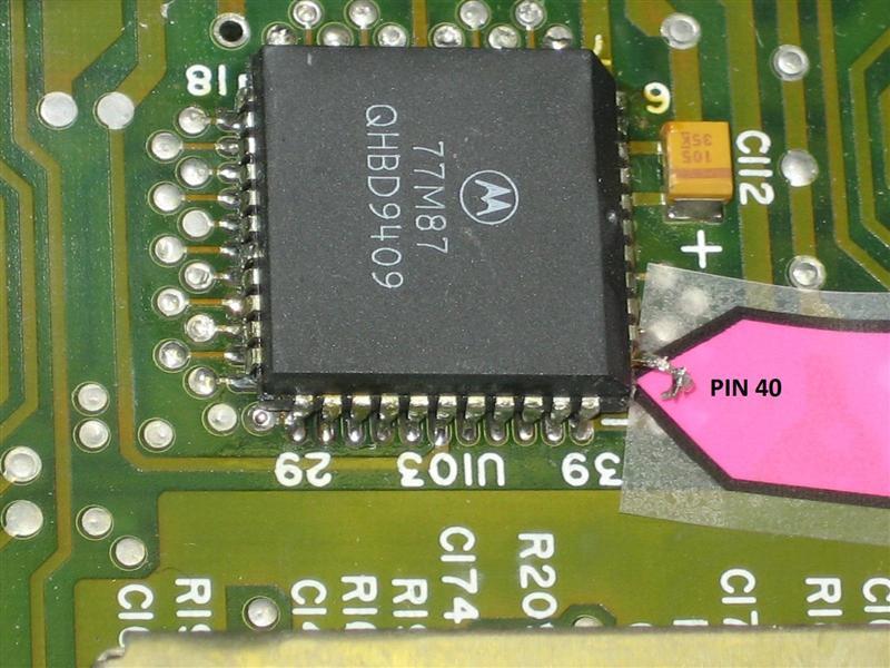
Rather than throw away the SIU and replace it with another that will also fail with time, my solution was to fix the problem. The fix is rather simple. Find U103 and cut pin 40 loose from the circuit board. U103 is a Serial Input/Output Integrated Circuit (SIOIC) and pin 40 is an active-low reset input that comes from one of the larger ICs in the shielded area. By cutting it loose, you prevent this reset signal from affecting the SIOIC. Here's a closeup showing U103 with pin 40 cut (photo courtesy of Jim K1VTY):
Your problem will go away and the radios will power up just fine. I have done this to a number of the SIU units that I have in service. Some are in commercial use and many are in ham service. These are great radios and should become plentiful here in the future with the re-banding date of January 01, 2013 not that far away.
Fixing the 99 Mode Limit (submitted by Jim K1VTY):
I had a UHF Spectra that would only go to 99 modes. The information given to me by another ham solved the problem. If you go in with LAB RSS and change memory location 6128 to a hex value of 80 (= 128 decimal) and save it, the radio will now allow you to fill up to 128 modes.
After you make that change, you will get a FAIL 01/82 error on the control head. Just read the radio again (F2) and then immediately save it right back (F8) with no changes. This will correct the checksum error caused by the memory change.
Now here is the important part. Add all the modes up to the 128 count, but do it by copying one of the existing modes like mode 1. If you don't do this, you will be missing some of the features like the multi-PL ability on the new modes you added. No problem if you just plain added them. Go back and do a copy into each of the new modes. When you're done with this step, save the changes to the radio. Then read it back before you go and put the correct mode information into each of the modes.
The reason for doing a save or write to the radio after each step, is the computer seems to lose some of the information if you make too many changes in too many places. By saving and writing after making just a few changes, you save the need for backtracking and getting frustrated when the information is messed up. I noticed that the PL tone on the direct or talk-around frequency would not be what I set it to.
Contact Information:
The author can be contacted at: his-callsign [ at ] comcast [ dot ] net.
Back to the top of the page
Up one level (Spectra index)
Up two levels (Moto index)
Go to the Home page
This page was conceived in March 2006.
Article text, layout, and photos Copyright © 2006 by Robert W. Meister WA1MIK unless otherwise noted.
This web page, this web site, the information presented in and on its pages and in these modifications and conversions is © Copyrighted 1995 and (date of last update) by Kevin Custer W3KKC and multiple originating authors. All Rights Reserved, including that of paper and web publication elsewhere.