Up two levels
Back to Home
the Low-band Syntor X9000
By John Haserick W1GPO
With Help From Robert Meister WA1MIK

|
Up one level Up two levels Back to Home |
Improving the Performance of the Low-band Syntor X9000 By John Haserick W1GPO With Help From Robert Meister WA1MIK |
|
Background:
One of Motorola's best ever low-band radios can still be enhanced for amateur use. As with every commercial low-band radio, the harmonic filter starts to attenuate above 50 MHz. In this radio, there is more than 1 dB loss above 53.5 MHz, which translates to at least 20 watts lost to heat. There is also slightly reduced receiver sensitivity, as the harmonic filter is between the antenna and the receiver. With the advent of good vacuum desolderers, the removal of the PA board is now much easier. We used a ZD-985 90-130 Watt model, set to a tip temperature of 815 degrees Fahrenheit, available from Memotronics for about $140 or a similar model ZD-915, available from Marlin P. Jones. The 1.3 mm tip needed to be enlarged slightly to fit loosely over the feed-through capacitor leads, but a stock 1.3 mm tip was fine for removing the coil shields. The bottom harmonic filter shield required a 100 Watt iron, solder wick, and patience to remove.
Getting to the Filter:
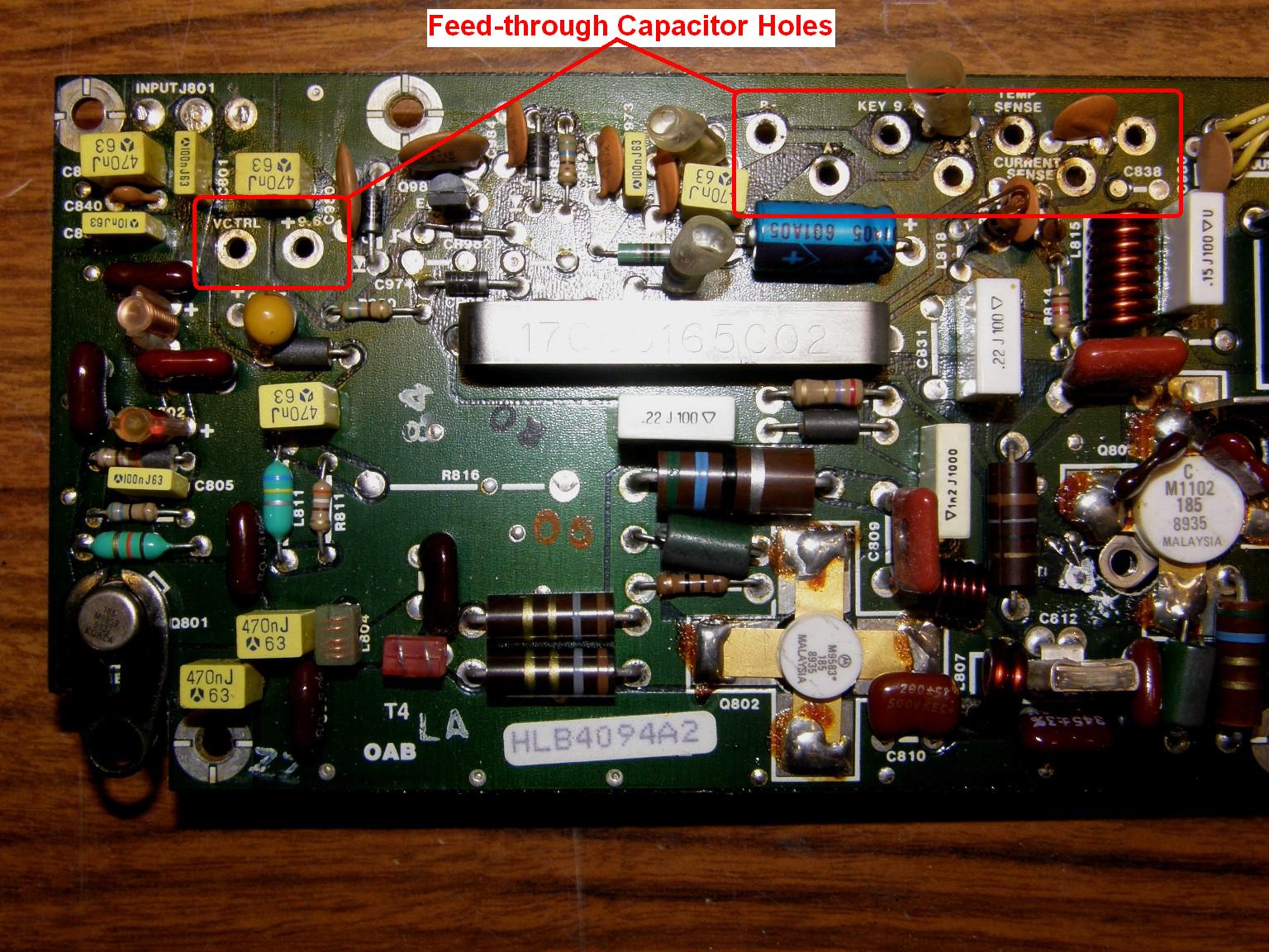
After removing the screws and two nuts that retain the PA circuit board to the heat sink, remove the solder from the nine feed-through capacitor leads holding down the board. Remove the RCA jack connector from the exciter, and push on the associated RCA plug to help free the board. There are ferrite cores beneath the board on each of the feed-through leads, so take care not to lose them. The photo below shows the board after being removed from the radio. Click on any of the photos or images for a larger view.
Modifying the Harmonic Filter:
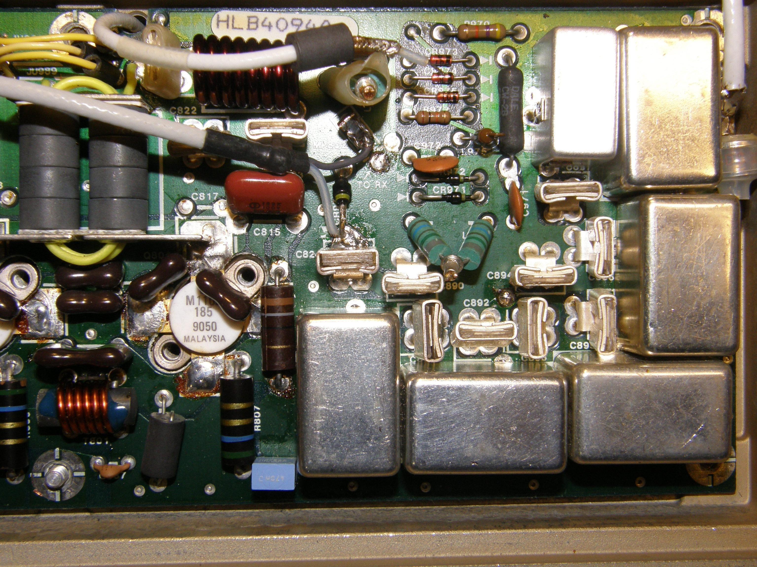
A large shield must be removed from the bottom of the circuit board as it restricts access to the harmonic filter shields. Remove the individual shields over the five harmonic filter coils to be spread. See the photo below. Remove only the five largest shields; the sixth smaller shield does not have to be removed, as there's no coil inside it.
For each coil, evenly spread the turns with a thin non-metal blade, starting with the coil end turns. Only the tops of the coils will spread, because the bottoms are fixed. Set each to the dimensions shown below, measured across the top of the coils from end to end:
| Coil | Stock | Modified |
|---|---|---|
| L890 6.5T | 14.5mm | 21.0mm |
| L891 5.5T | 12.0mm | 18.0mm |
| L892 4.5T | 11.0mm | 13.0mm |
| L893 6.5T | 14.5mm | 21.0mm |
| L894 7.5T | 17.0mm | 24.0mm |
The image below shows the harmonic filter schematic with the coils that you need to spread out. The relevant information has been previously tabulated.

The photo below shows what the harmonic filter coils look like after having their turns spread according to the table above. Note the shields at the top of the photo.
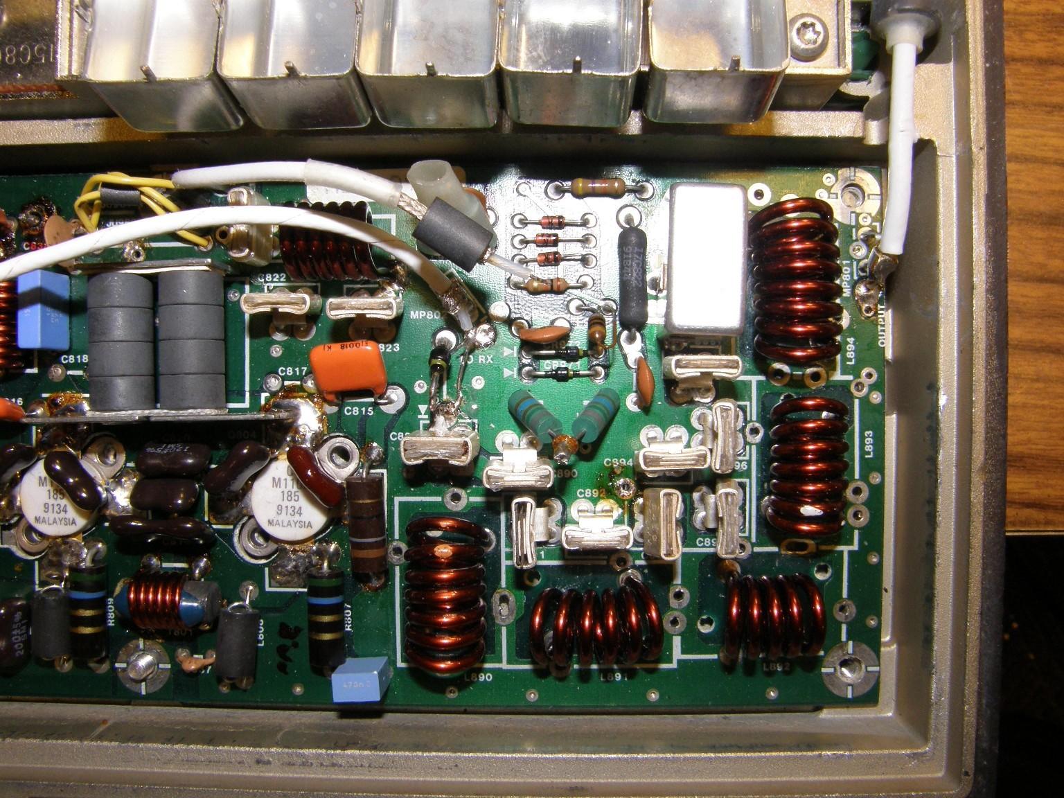
Do not be tempted to touch the 7-turn unshielded PA coil L810, or you will lose 10 meters. Just changing the harmonic filter has no effect on frequencies below 6 meters, as it is strictly a low-pass filter without ripple below cut-off. Needless to say, wipe off and apply new heat sink compound the three power transistors. There is clear greasy compound on the square insulator for the control transistor, so keep it clean.
Results:
With power at 52.49 MHz set to 105 watts, current limit to 22A at 14V, the results we got after filter change is tabulated below:
| MHz | Watts | Amps |
|---|---|---|
| 53.97 | 98 | 18.0 |
| 53.29 | 105 | 17.5 |
| 52.49 | 105 | 17.5 |
| 51.50 | 105 | 17.0 |
| 29.60 | 100 | 22.0 |
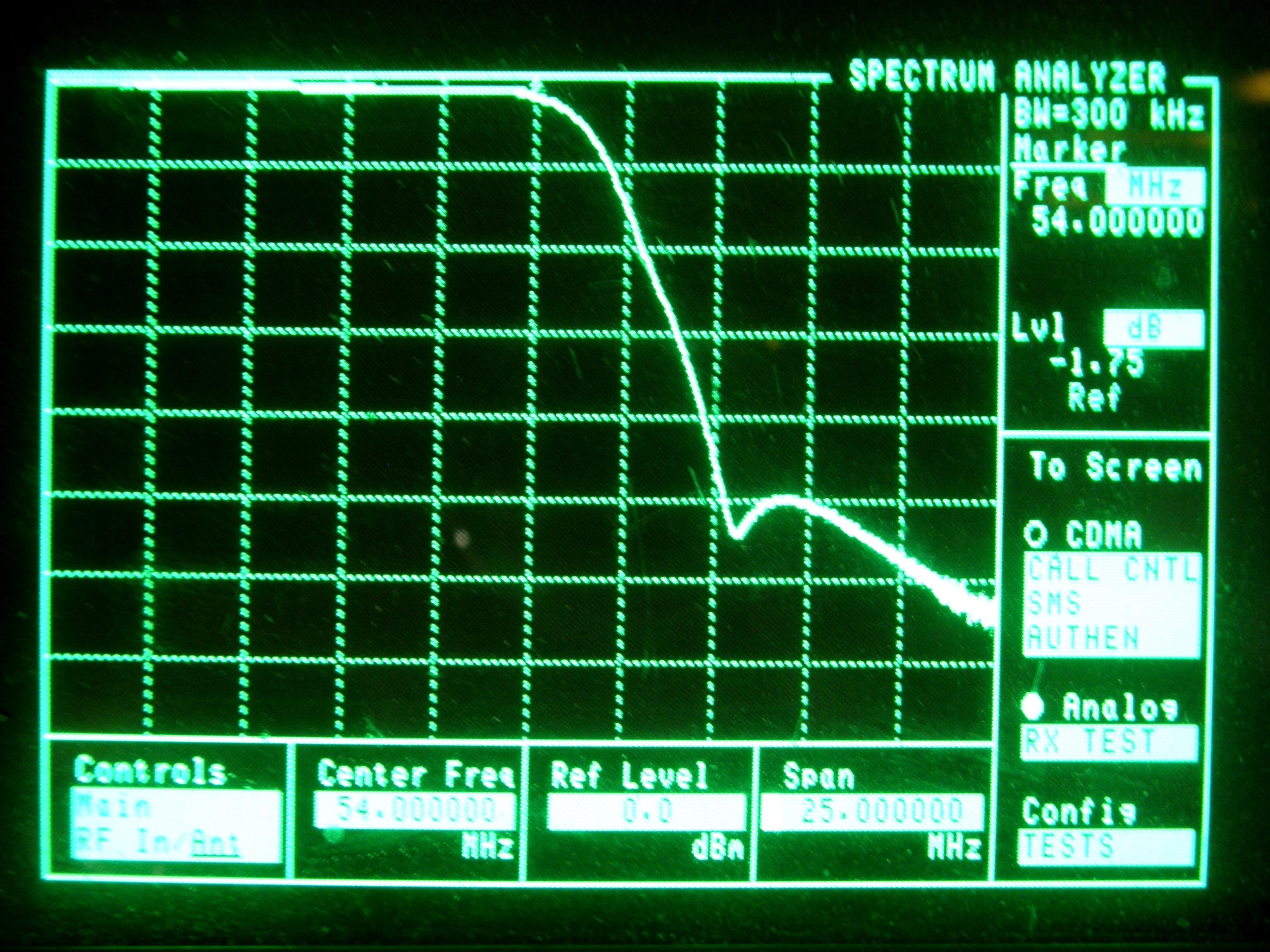
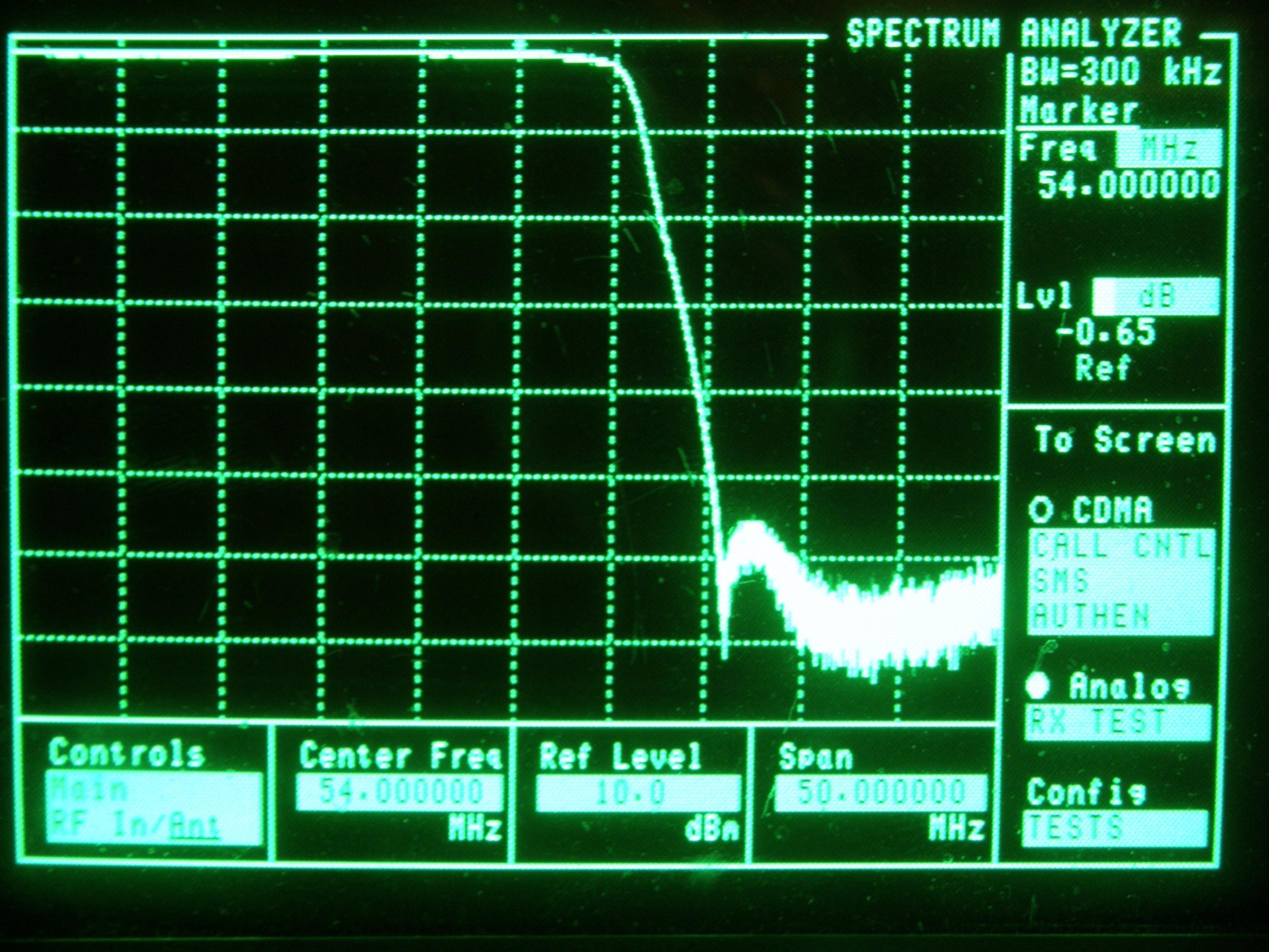
All scope pictures are with marker at the center at 54 MHz, 25 MHz sweep width, so each vertical line represents 2.5 MHz. The top line represents 0 dB of loss. This image shows the original harmonic filter response that starts rolling off just below 54 MHz.
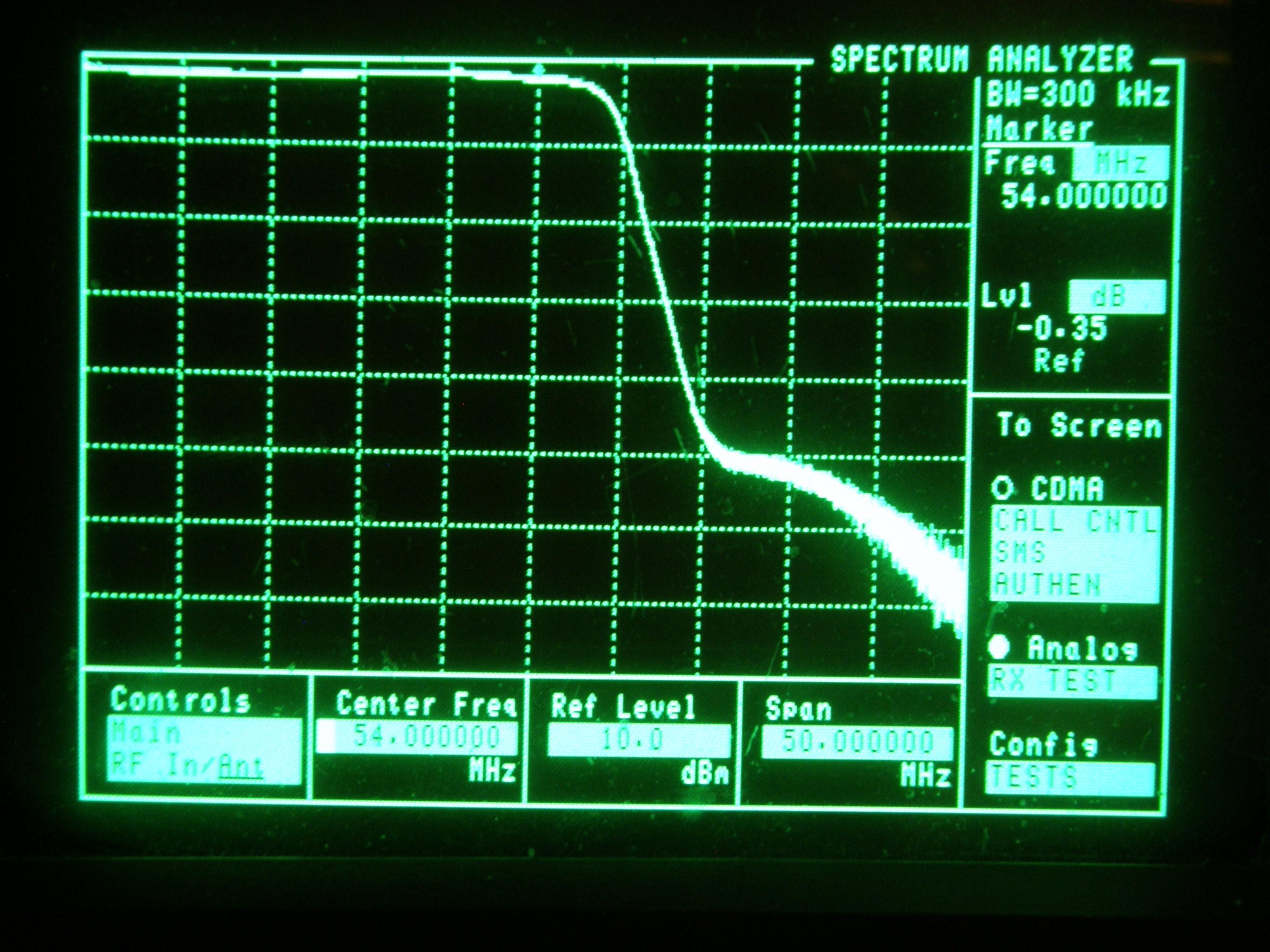
This image shows the modified harmonic filter response that starts rolling off at just over 57 MHz.

Another radio was similarly modified; a spectrum analyzer trace is shown below. The center is 54 MHz but the total span is 50 MHz, so it shows the response down to 29 MHz is as flat as a pancake.
After the final tuning, we noticed about 10% more output power and increased receiver sensitivity on 6-meters, as long as no channel 2 or 3 TV transmitters are nearby. The filter loss is 6.6dB at 60 MHz.
Further Filter Improvements:
I did another X9000 harmonic filter change because the radio was drawing 19.5A for 100W on 52.49 MHz, whereas the usual is 18-18.5A. This time we noticed that the smallest coil, L892, was the MOST critical in adjusting the frequency of the knee, and also the levelness of the pass up to the knee. That was surprising to me, because usually the coil with the largest number of turns influences the cut off the most, and therefore I had always assumed that L892 had more to do with the third harmonic. It turned out if L892 was set at 13mm instead of 16mm, with the other four coils set as in the table above, all of 6M took on the same loss as low-band below 50 MHz! Also if any coils are offset, i.e. not centered inside the can, that will throw off the required coil spreads, as the aluminum coil shield raises the resonant frequency of the coil. Now the radio draws 16A for 100W throughout 6M! That is the most X9000 TX efficiency we ever achieved on 6M.
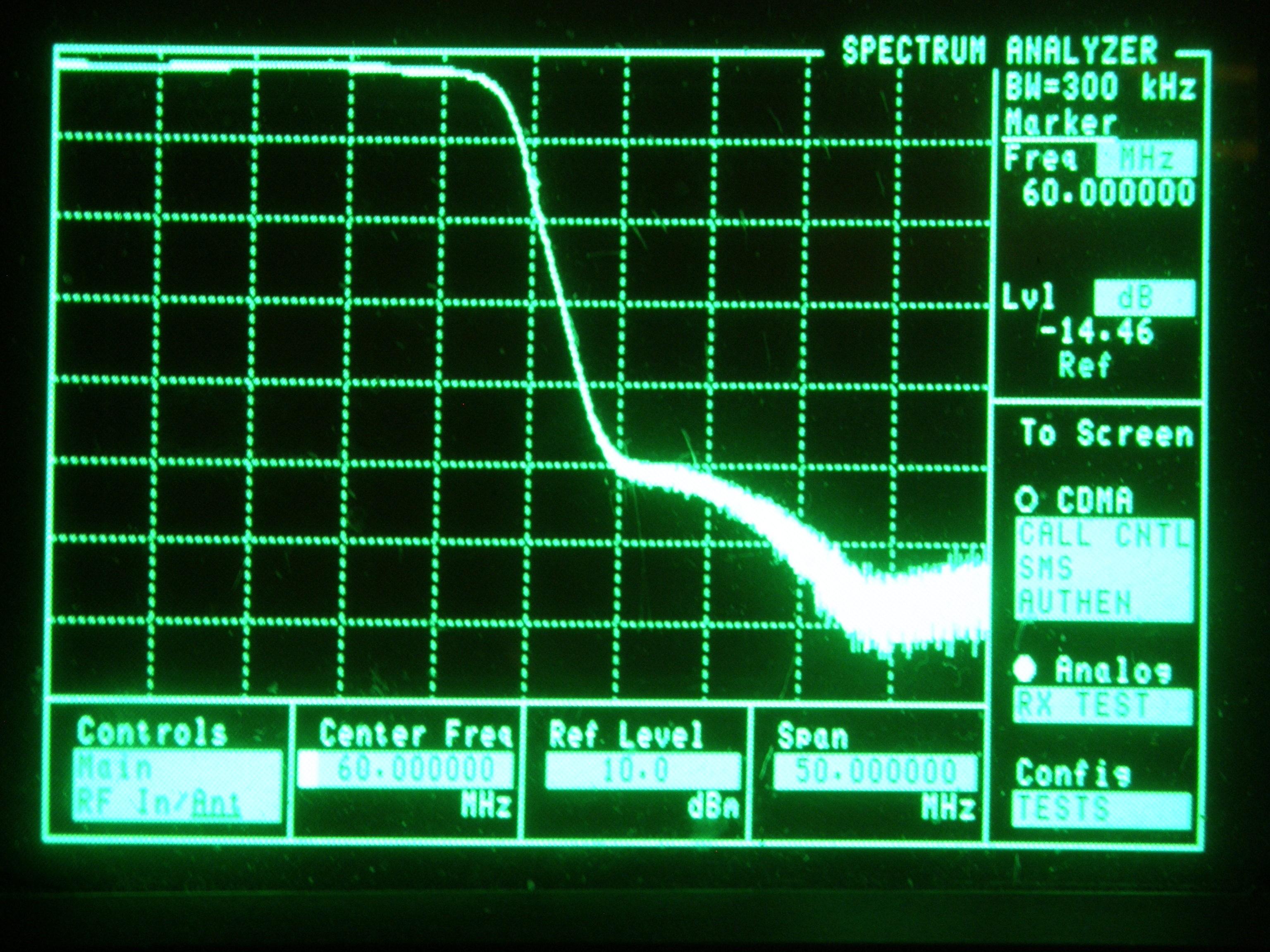
The TX itself, before the harmonic filter, does lose efficiency below 31 MHz, so the radio draws 20.5A for 75W out at 29.6 MHz. For this reason, I recommend setting the current limit to 21A, not fully on as Motorola recommends, so 10M operation will not overheat the PA. The additional advantage is if the engine is off, the radio draws less current from the battery, as it does not try to keep all frequencies at 100W. The photo below shows the improved filter response.
The photo below shows shows 14.46 dB loss at 60 MHz, nearly an 8 dB improvement in the reduction at 60 MHz over when L892 was spread to 16mm. Note that the center frequency in this spectrum is 60 MHz, not 54 MHz like almost all of the others.
Additional Improvements:
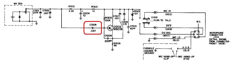
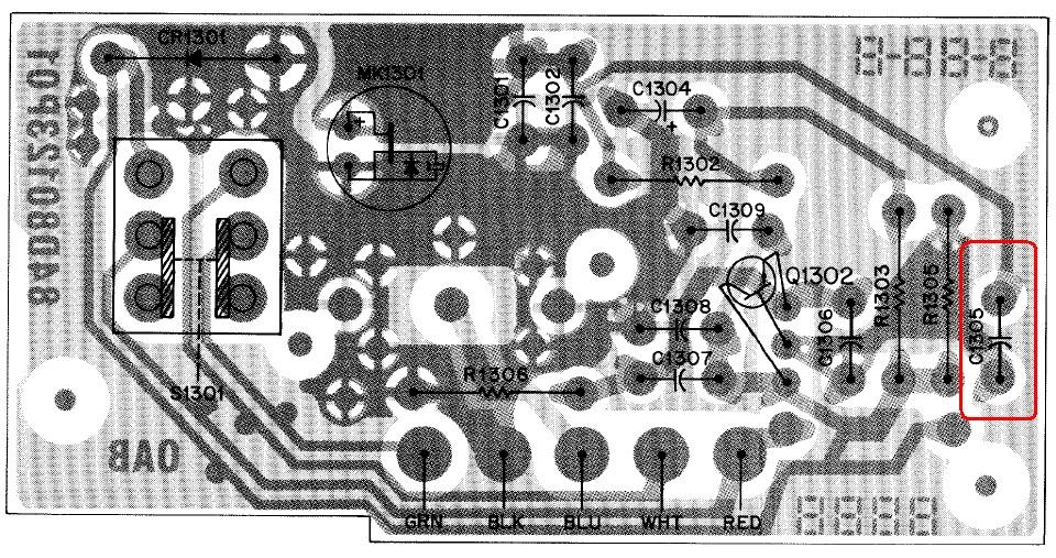
Another modification should be made to the mike to improve audio from tinny to good communications quality. The radio itself has a very straight 6dB pre-emphasis from 300-2800 Hz; all speech tailoring is in the mike. Change the 0.047uF C1305 to 0.33uF. C1305 is closest to where the mike cord exits the circuit board. 0.47uf gives flat natural audio. See the images below.
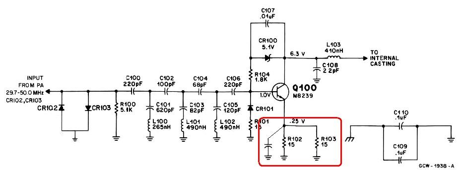
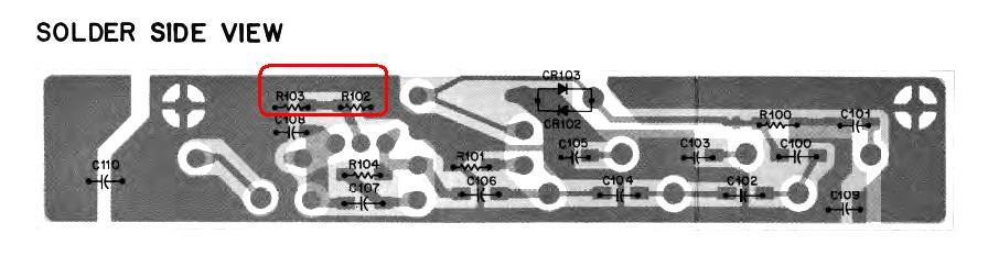
Receiver sensitivity can be improved to 0.25uV for 20 dB quieting by adding a 0.001uF chip cap across the pre-amp Q100 emitter resistors. There was 10 dB increase in intermod, which may not be noticeable in many areas. See the images below.
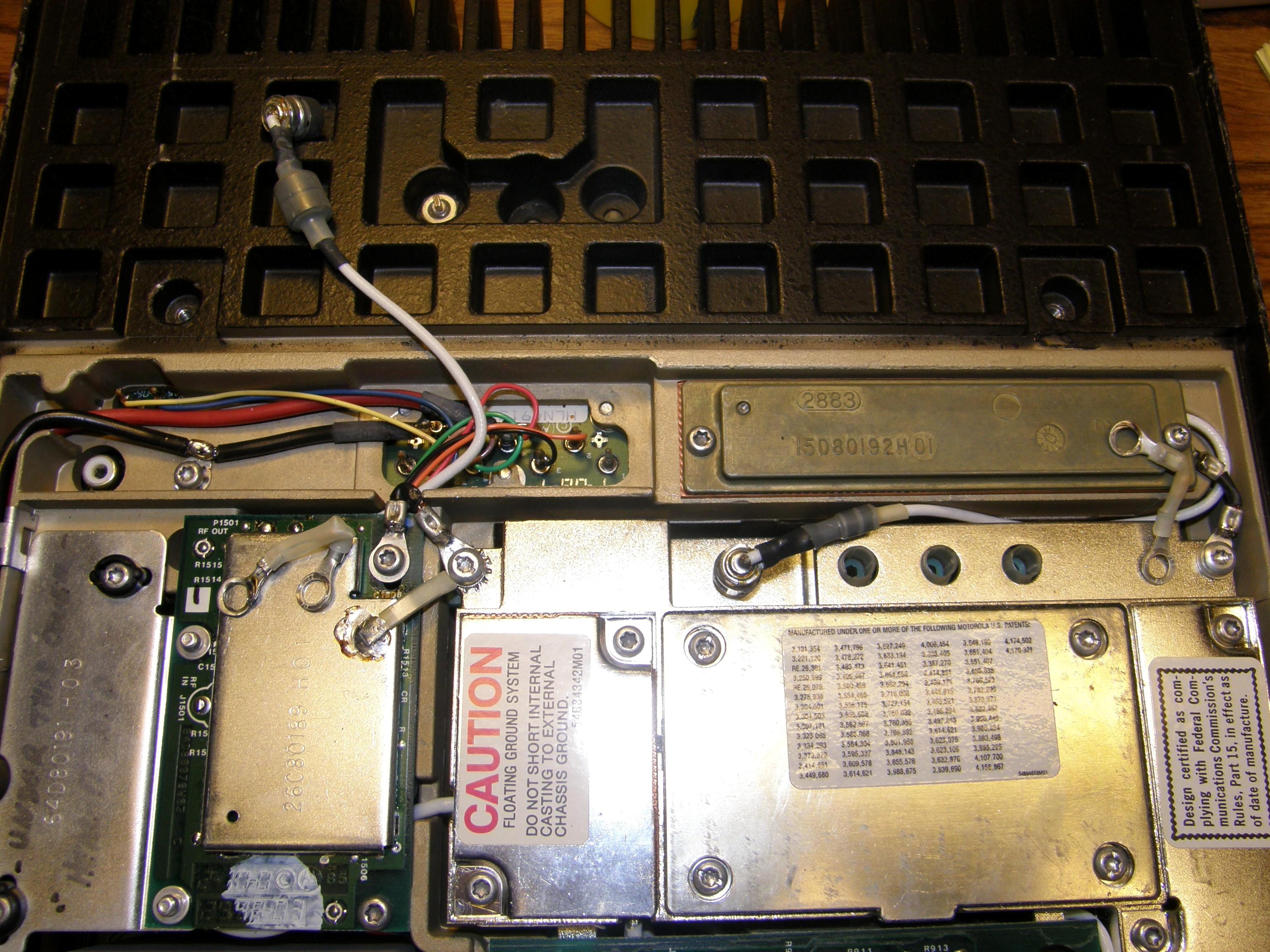
A VERY important modification to the radio that would have saved three X9000 radios from severe self-destruction from a voltage difference between the antenna connector shield (drawer ground) and A-, is to create a negative ground only radio by doing away with the radio floating ground. You can do this by simply bonding the A- lead to the drawer ground, and changing two capacitive jumpers to DC jumpers between chassis ground and internal casting ground, just what the warning labels say what not to do (see photo below)!
Acknowledgements and Credits:
Schematics and printed circuit board X-ray views came from the Motorola Syntor X9000 Low-Band Radio System Service Manual, p/n 6880101W95-D.
Photographs were taken by the author unless otherwise indicated.
I thank Bob WA1MIK for his invaluable advice and assistance with creating this article.
Contact Information:
The author can be contacted at: jhaserick84 [ at ] comcast [ dot ] net.
Back to the top of the page
Up one level
Up two levels
Back to Home
This article originally written 12-May-15.
This web page, this web site, the information presented in and on its pages and in these modifications and conversions is © Copyrighted 1995 and (date of last update) by Kevin Custer W3KKC and multiple originating authors. All Rights Reserved, including that of paper and web publication elsewhere.