Back to Home
XPR 8300 MotoTRBO Repeater
to a CAT-200B Controller
By Robert W. Meister WA1MIK

|
Up one level Back to Home |
Interfacing an XPR 8300 MotoTRBO Repeater to a CAT-200B Controller By Robert W. Meister WA1MIK |
|
What I Started With:
This CAT-200B repeater controller was initially connected to a pair of Motorola MaxTrac mobile radios to make a simple UHF repeater. After the MaxTrac transmitter overheated one day, an external Henry 100w power amplifier was attached and the MaxTrac transmitter's output power was reduced to 6 watts. Initially, a pair of 8-pin round DIN connectors were installed on the back of the controller enclosure to interface to the two radios. These were replaced with a single DE-9M connector and a new radio cable was made. The table below shows the wiring between the front panel MIC jacks on the two MaxTrac radios and the DE-9 connector on the back of the enclosure that houses the CAT-200B, DL-1000 delay board, and CI-200 serial interface. This DE-9M radio jack is wired to a DB-25M that plugs into the DB-25F on the CAT-200B controller board.
CAT-200B Repeater Controller Pin Assignments
| DE-9 Pin | RX Signal | RX RJ45 | RX Color |
TX Signal | TX RJ45 | TX Color | CAT Pin | CAT Signal |
|---|---|---|---|---|---|---|---|---|
| [3] 1 | GND [3] | 4 | Green | [2] 17 | Ground | |||
| 2 | COR Out | 1 | Brown | [1] 6 | COR #1 In | |||
| 3 | Aud Out | 8 | Gray | 13 | RX Aud #1 In | |||
| 4 | Mon In | 3 | Yellow | 14 | Switch #1 Out | |||
| 5 | (spare) | --- | --- | |||||
| [3] 6 | GND [3] | 4 | Green | [2] 25 | Ground | |||
| 7 | PTT In | 6 | Black | 10 | PTT #1 Out | |||
| 8 | Aud In | 5 | Red | 11 | TX Aud #1 Out | |||
| 9 | (spare) | --- | --- |
NOTES:
Flat 8-conductor cable with RJ45 modular connectors carries the signals from the DE-9 on the back of the controller box to the two radios. These two cables are soldered to a DE-9F connector. I chose a female connector in case it gets unplugged from the controller and a male connector's pins could get shorted to ground. The table below shows the wire colors and signals.
RJ45 MIC Jack (MaxTrac Radio) Flat Cable Wire Colors
| Pin | Color | Signal or Function |
|---|---|---|
| 1 | Brown | COR + CTCSS Out |
| 2 | Blue | (spare) |
| 3 | Yellow | Monitor/Hang-Up In |
| 4 | Green | Ground |
| 5 | Red | TX Audio In |
| 6 | Black | PTT In |
| 7 | Orange | Programming |
| 8 | Gray | RX Audio Out |
A Step Up:
A used Motorola XPR 8300 MotoTRBO repeater was acquired in the hopes of using it to replace the two MaxTrac mobile radios. The 100w power amplifier would be reconfigured for 30w input; see this article for more details.
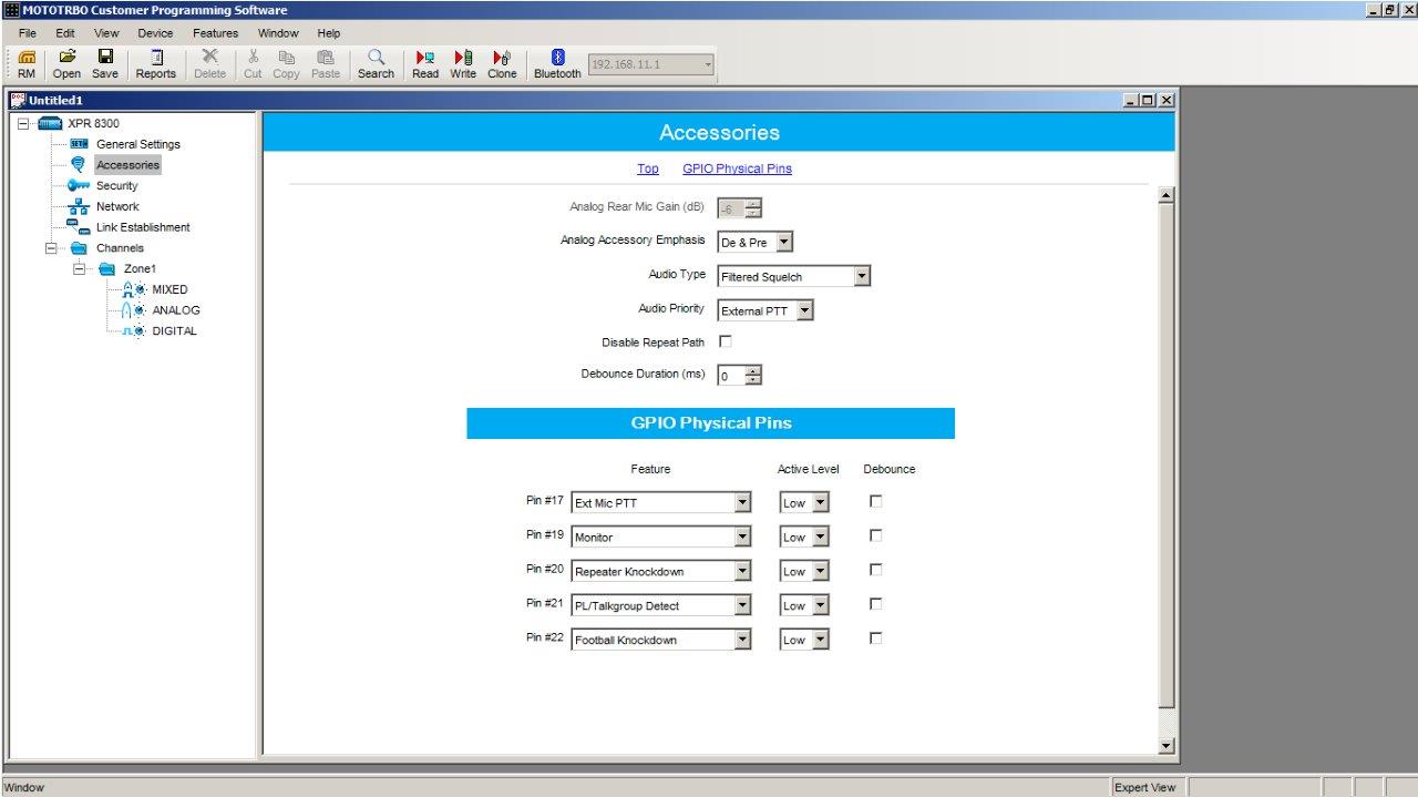
The XPR 8300 is capable of analog or digital modes, automatically switching between the two depending on the signal it receives, once the appropriate enhancement key is installed, which this repeater already had. Internally, the XPR 8300 is a pair of MotoTRBO radios with a simple controller that controls repeater hang-time, repeater timeout, and can send a CW identification. I found documentation for the 26-pin MAP Accessory Connector and figured out what signals were available and programmed some of the GP I/O signals to give me additional functionality. All of the logic signals were set for active-low, no debounce, as shown in the screenshot below.
The table below shows the various pins and how I programmed them, and also how they were wired up to the CAT-200B controller.
26-pin MAP Accessory Connector (XPR 8300) Signal Assignments
| XPR Pin | Wire Color | XPR Signal or Function |
DE-9 Pin | CAT Signal |
|---|---|---|---|---|
| 11 | Brown | TX Audio Input (Analog only) | 8 | TX Audio #1 Output |
| 12 | Red | Ground | 1,6 | Ground |
| 14 | Orange | RX Audio Output (Analog only) | 3 | RX Audio #1 Input |
| 17 | Yellow | External PTT Input (Analog only) | 7 | PTT #1 Output |
| 19 | Green | Monitor Input (Analog only) | 5 | N/C |
| 20 | Blue | Repeater Knockdown Input | 4 | Switch #1 Output |
| 21 | Black | PL/Talkgroup Detect Output (COR) | 2 | COR #1 Input |
| 22 | White | Football Knockdown Input | 9 | N/C |
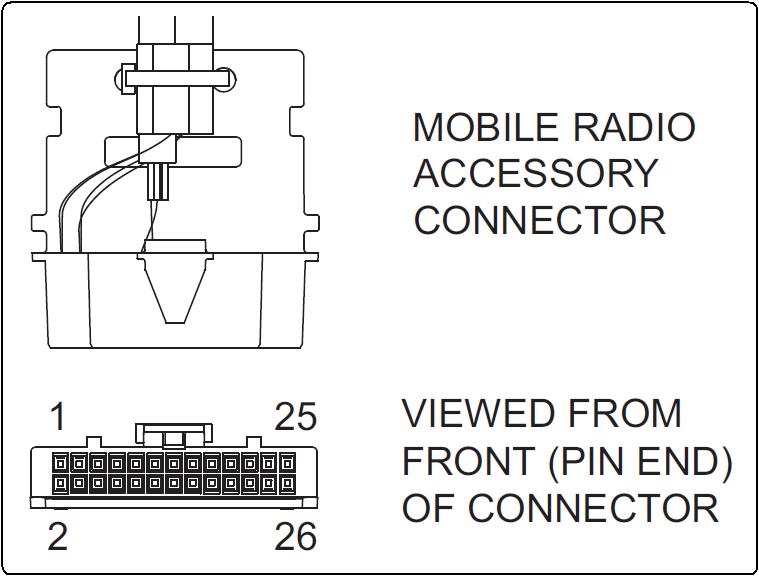
Looking into the cable (insertion) end of the Accessory Plug:
| 25 | 23 | 21 | 19 | 17 | 15 | 13 | 11 | 9 | 7 | 5 | 3 | 1 |
| 26 | 24 | 22 | 20 | 18 | 16 | 14 | 12 | 10 | 8 | 6 | 4 | 2 |
The cable strain relief is along the bottom surface. The diagram below shows the connector from a different angle. Click on it for a larger view.
Notes about specific pins and signals, direct from the documentation; not all of it is true.
Additional information on the accessory connector can be found in this 50kb page extracted from the service manual.
Testing, Testing, 1, 2, 3:
A friend made an 8-conductor cable with the appropriate female contacts so all I had to do was insert them into the appropriate pins (numbers within parentheses) on the 26-pin accessory connector plug. Tests were performed with various pins connected together. Here are the results.
TX Audio Input (11) to RX Audio Output (14), TX PTT Input (17) to RX COR Output (21): the repeater would repeat analog or digital signals. I think these were all ignored and the internal controller did all the work, as Repeater Knockdown (20) was NOT grounded.
After adding Repeater Knockdown (20) to Ground (12): digital repeating was disabled. If PTT to COR was disconnected, analog repeating was also disabled. So it seems that Repeater Knockdown is more of an "Internal Repeater Path Disable" when grounded. The PTT line only works in analog mode, even though the RX COR is active when receiving a digital signal. To disable the internal controller and utilize an external controller, this signal must be grounded. Even in that situation, the external controller will only operate with an analog signal; a digital signal will activate the COR output but the PTT input is ignored in digital mode and no audio would pass.
The Monitor input (19) doesn't seem to disable coded squelch at all. It may be a remnant of a similar line on a MotoTRBO mobile radio's accessory port. I was hoping this would put the receiver into carrier-squelch mode, but it didn't do anything on this station.
The Football Knockdown (22) didn't seem to do anything at all. Supposedly this input is meant to completely disable the repeater transmitter during football plays, to eliminate the possibility of the coaches instructing the quarterback.
Final Tests:
I wired the XPR 8300's accessory connector according to the wiring diagram above. In the CAT-200B, Zone 1, Position 1 controls the repeater transmitter: enabled (1) or disabled (0), and Zone 3, Position 5 controls Switched Output #1: on/grounded (1) or off/high (0). (This line originally went to the MaxTrac receiver's Hand-Up input; ON put the radio into coded-squelch mode; OFF put it into carrier-squelch mode. I was hoping for a similar effect on the XPR 8300.) After applying power, I performed the following tests in this order, using Motorola XPR7550e and Yaesu VX-8 handheld radios.
With Zone 3, Position 5 ON (1), the repeater's internal controller is disabled (Repeater Knockdown is grounded). The CAT-200B controller handles all repeating if Zone 1, Position 1 is ON (1). Only analog operation works and you get muted DTMF digits and a courtesy beep (and hang time).
With Zone 1, Position 1 OFF (0), the repeater is shut off. The internal controller's CW ID still operates.
With Zone 3, Position 5 OFF (0), the repeater's internal controller is enabled (Repeater Knockdown is high). The internal controller passes analog and digital signals as they are encountered and you get no courtesy beep and no muting of DTMF digits. The CAT-200B will transmit messages in response to DTMF commands on the analog channel. Recall that Zone 1, Position 1 is still OFF, so the CAT-200B can't key the transmitter.
With Zone 3, Position 5 OFF (0) and Zone 1, position 1 ON (1), you get a courtesy beep, hang-time, and muting of DTMF digits on an analog signal. A digital signal also produces a courtesy beep (and hang time) when the incoming signal un-keys, because the COR signal also follows the incoming digital signal.
The following table summarizes the possible states of Zone 3, Position 5 (Switch #1 Output), and Zone 1, Position 1 (Repeater Transmit Enable).
Control Signal Choices
| Z3-P5 | Z1-P1 | What Works | Controller | Notes and Conditions |
|---|---|---|---|---|
| OFF | OFF | Analog + Digital | Internal | Stand-Alone XPR 8300 |
| OFF | ON | Analog + Digital | Both | Invalid Condition - DO NOT USE! |
| ON | OFF | Neither | External | Repeater OFF, except for XPR CW ID |
| ON | ON | Analog Only | External | Analog ONLY. MaxTrac Mode |
When both controllers are active, the digital signal goes through the internal controller and ignores the TX Audio Input and produces no RX Audio Ouput, but it still activates the COR signal. This causes the CAT-200B controller to produce a courtesy beep and key the transmitter when the digital input signal goes away. Apparently whenever the external PTT signal is active, the TX Audio Input signal is also active and audio goes through only the external controller. I got repeated audio whether the CAT-200B was connected or not, and they both sounded fine. The MotoTRBO handheld I was using never heard the analog activity but my Yaesu VX-8 picked it right up.
Either controller will attempt to send out one final CW ID after a period of inactivity. The XPR 8300's internal controller will always send this out in analog mode even if Repeater Knockdown is active. The CAT-200B controller will not transmit anything if it has been commanded not to (Zone 1, Position 1 set to 0/OFF).
The XPR 8300's radios do NOT decode digital data to analog audio, nor does it encode analog audio to digital data. You can't transmit a digital signal from the accessory port; this is partly because the MotoTRBO system allows two independent conversations (or time slots) to be active at the same time and there's only one PTT Input signal, so you can't choose which one to utilize. The external controller can only operate with analog signals, but at least that gives you some means of on/off control over the repeater, as required by FCC rules and regulations.
Acknowledgements and Credits:
Thanks go to Jim N1GTL for loaning me his XPR 7330e handheld to test this repeater and for building the accessory/programming cable.
Accessory connector documentation came from the XPR 8300 Service manual and some web research.
Contact Information:
The author can be contacted at: his-callsign [ at ] comcast [ dot ] net.
This page created 25-Jan-2018.
Go to the top of this page
Up one level
Go to Home
Article text, layout, and HTML © Copyright 2018 By Robert W. Meister WA1MIK
This web page, this web site, the information presented in and on its pages and in these modifications and conversions is © Copyrighted 1995 and (date of last update) by Kevin Custer W3KKC and multiple originating authors. All Rights Reserved, including that of paper and web publication elsewhere.