the Repeater-Builder
AP-50 Audio Processor
By Robert W. Meister WA1MIK

|
Test and Evaluation of the Repeater-Builder AP-50 Audio Processor By Robert W. Meister WA1MIK |
|
This unit is both an adjustable low-pass filter and an audio clipper. Each feature operates independently and smoothly.
The default input jumper SJ6 (normal gain) and default output jumper SJ1 (normal gain) were installed when I received the unit. Only one jumper in each set should be installed at any time.
At 1000 Hz, with both gain pots set fully clockwise (maximum gain) and the audio input level set to -20dBm (approximately 77mVAC or 200mVp-p), the output was -1.5dBm (approximately 700mVAC or 2Vp-p). Distortion at this point was about 2% but it was not visible on the oscilloscope. When I activated a 30 kHz low-pass filter on my audio analyzer, the distortion reduced to 0.05%, so it appears the 2% value is high-frequency noise. This filter remained enabled during all further tests. I eventually discovered a 340 kHz 5Vp-p square wave signal on U2 pin 11 as the source of this noise. This signal changes frequency as the filter is tuned, from about 200 kHz to over 600 kHz.
The DC input current was 4.5mA at 13.8VDC input regardless of input frequency or level.
Filter Operation and Tests:
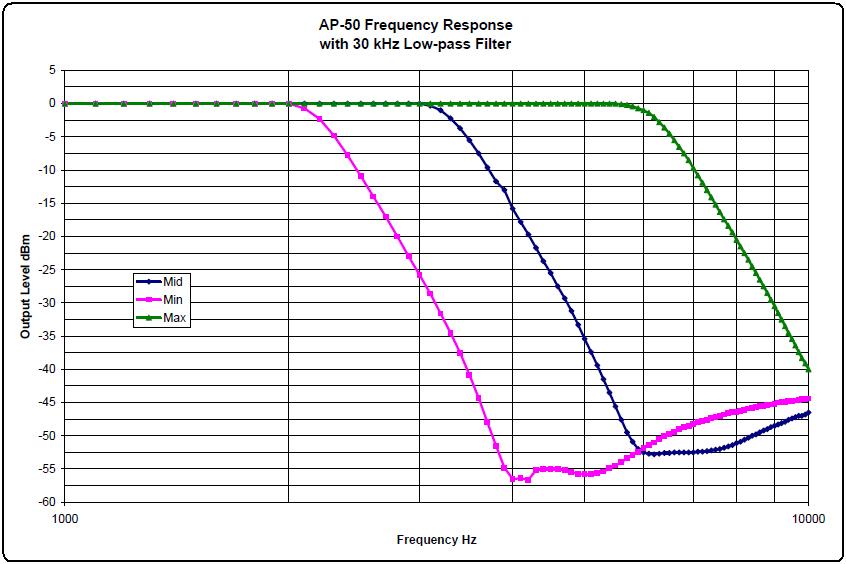
The minimum frequency to obtain a 3dB drop in output level was 2.2 kHz. The maximum frequency to obtain a 3dB drop in output level was 6.3 kHz. I set the cutoff frequency pot to the midpoint, about 3.5 kHz.
The audio stages in the AP-50 are flat from 10 Hz up to well over 10 kHz; only the filter circuit affects the frequency response.
To measure the frequency response, I fed in a 100 Hz signal at 0dBm while I viewed the output signal with the scope, and adjusted the input pot a bit below the clip point, where the distortion started to increase. I set the deviation pot for 0dBm output. I ran the input frequencies from 1,000 to 10,000 Hz in 100 Hz steps. The graph below shows the output level with the 30 kHz low-pass filter, at the minimum, middle, and maximum settings of the filter frequency pot. Click on the graph for a larger view.
Clipper Operation and Tests:
To get the unit to clip, I fed in a 100 Hz tone at 0dBm (775mVAC) and turned the input level pot until I could see some clipping on an oscilloscope. The waveform was always symmetrical. Below 200 Hz the top and bottom were flat as the signal hit the power supply rails and produced a 4Vp-p signal (because of where the deviation pot was set). At 1000 Hz the waveform tended to overshoot and have multiple peaks, due to some of the 3rd harmonic passing through the low-pass filter. This harmonic distortion was gone at 2000 Hz and the output was sinusoidal again. Clipping happens within U2, the unmarked filter/amplifier IC. The U1A amplifier stage is designed so it will not clip under any configuration.
With the pots set as they were for the frequency response tests (0dBm input and output, filter pot mid-way), I increased the input level pot to its maximum clockwise setting and increased the input signal level to +10dBm (2.4VAC) to purposely overdrive the unit and force it to clip. I connected the scope to U2 pin 4, actually the feed-through hole next to R15 (a 150k resistor) to view the output of the first amplifier. The waveform was nicely clipped at 5V peak-to-peak amplitude, because this is the voltage supply to U2. This clipping action was exhibited from 10 Hz to 100 kHz and was nice and square. The scope trace below shows a 1 kHz signal in full clipping.
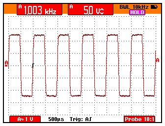
You can't see this at the output of the AP-50 unless you use a frequency below about 200 Hz. This clipped waveform is a square wave full of odd harmonics. Most of those harmonics are eliminated by the low-pass filter in U2, so you end up with essentially the original signal: a clean sine wave. If the filter frequency is adjusted higher, some of those harmonics make it through the filter and you get ripple and reduced amplitude peaks when viewed on a scope, but the audio is still nice and clean leaving the AP-50.
Pre-Emphasis and De-Emphasis Tests:
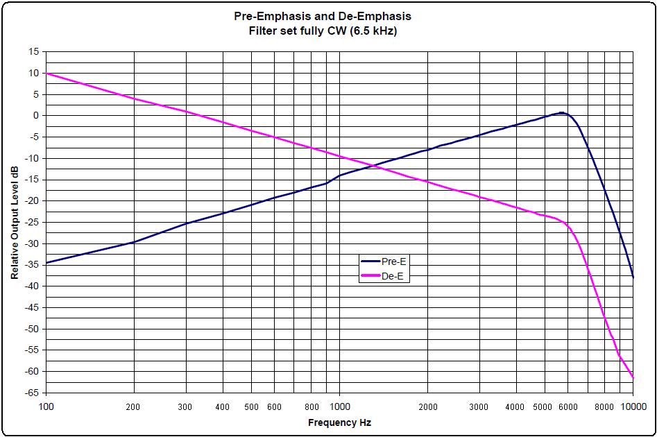
SJ6 was removed and SJ4 was installed to activate the pre-emphasis on the input of the AP-50. The input level was set to -10dBm and the filter was set fully clockwise to have minimal effect. SJ4 was removed and SJ6 was reinstalled after testing. The standard pre-emphasis is 6dB per octave.
SJ1 was removed and SJ3 was installed to activate the de-emphasis on the output of the AP-50. The input level was set to -13dBm and the filter was set fully clockwise to have minimal effect. SJ3 was removed and SJ1 was reinstalled after testing. The standard de-emphasis is 6dB per octave.
The results are plotted in the graph below. Click on it for a larger view.
Test Equipment:
HP 339A Audio Analyzer
Fluke 189 Digital Multi-Meter
Fluke 199C Oscilloscope
Contact Information:
The author can be contacted at: his-callsign [ at ] comcast [ dot ] net.
This page originally posted on Wednesday 02-Oct-2019
Article text, artistic layout, all images, and hand-coded HTML © Copyright 2019 by Robert W. Meister WA1MIK.
This web page, this web site, the information presented in and on its pages and in these modifications and conversions is © Copyrighted 1995 and (date of last update) by Robert Meister WA1MIK. All Rights Reserved, including that of paper and web publication elsewhere.