Go to the Home page
By Robert W. Meister WA1MIK (SK)
Maintained by Mike Morris WA6ILQ
Photos by WA1MIK unless otherwise noted

|
Up one level Go to the Home page |
Photo Tour of a Bird Wattmeter Element By Robert W. Meister WA1MIK (SK) Maintained by Mike Morris WA6ILQ Photos by WA1MIK unless otherwise noted |
|
I bought two Bird elements on a popular auction site: 5 watt, 400-1000 MHz (5E) and 100 watt, 400-1000 MHz (100E). Both were listed as new old stock (NOS). I put them into my meter about a week after they arrived, connected the meter to a radio and dummy load, keyed the radio, and the needle moved for each one.
The other day I picked up a used 80 watt UHF base station and wanted to measure the output power. I put the Bird 100 watt element into my Dielectric (also known as Sola Basic) 1000 wattmeter, connected the meter between the power amplifier and the dummy load, and keyed the transmitter. The meter crept up to about 40-50 watts but was erratic and drifted all over the place. I fiddled with the output power adjustment but could not get more than 60 watts out of the station. When I pushed it higher, the station faulted and stopped transmitting. Every time I keyed the station, I got a new reading on the meter. Not good. I assumed it was the station that had problems. Never assume!
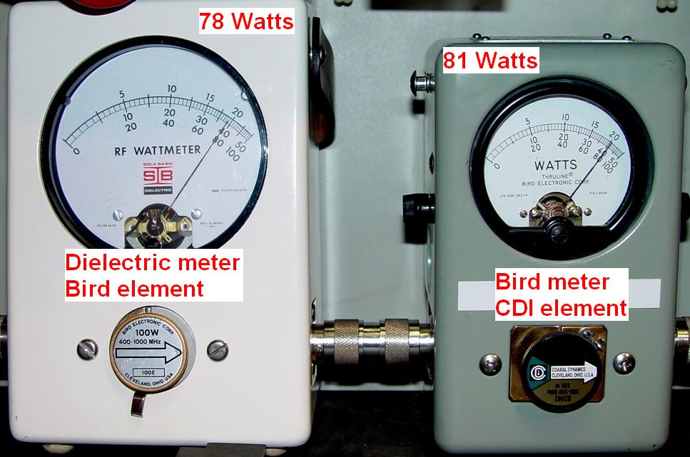
I took my box of RF adapters to the station so I could test the receiver. This same box also stores my Bird 43 wattmeter (official name: RF Directional Thruline Wattmeter Model 43). On a whim, I connected my Bird wattmeter to the station in place of the Dielectric meter. I also inserted my known good CDI (Coaxial Dynamics, Inc.) 100 watt element into the Bird. I keyed the station and the meter pegged at over 100 watts! I quickly turned it down to 80 watts and it was nice and steady. Hmmm, something's fishy.
I put the new Bird element into the Bird wattmeter and keyed the station. The meter went up to about 40 watts and was unstable. Back to the CDI element and it was still making a constant 80 watts like it should.
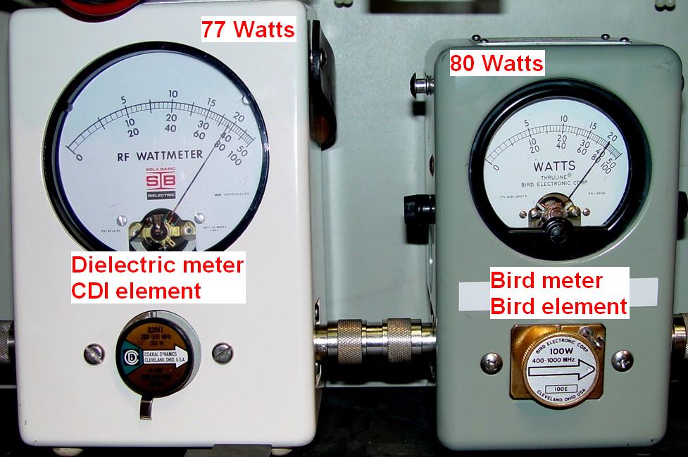
I put the Dielectric meter inline with the Bird meter and put the CDI element in the Dielectric meter. I keyed the station and the meter read 81 watts. Close enough for me.
I put the Bird element into the Dielectric meter and it read about 40 watts and was unstable. Let's see: the CDI element works in both meters while the Bird element fails in both meters. Aha. I think I see the problem. Luckily it's not the base station that's at fault.
A new CDI element costs about $70. I paid that much for the pair of used Bird elements. I don't know if Bird or CDI repairs these elements, but if so, it's probably more than the cost of a new one. I figured "What have I got to lose? Maybe I can take it apart myself and see if I can find anything wrong." So I did.
Taking the top of the element apart:
I had discovered a web page (no longer valid) by Jim K5LAD (SK) that showed the insides of some Bird elements and helped me get mine apart. The photos and descriptions shown below document what I found in my element as I disassembled it.
2024-04 update from the page maintainer: The K5LAD article is valid, plus it has 4 sub-pages. It was just offline for a while. Look here.
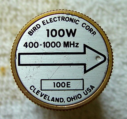
Here's the original Bird element:
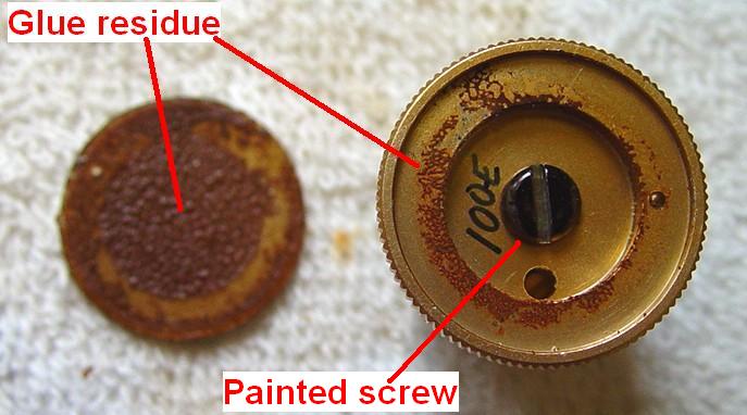
I tried prying the top aluminum cover off, breaking several knife blades in the process. It's well attached with some kind of adhesive. I soaked the knurled end of the element for several hours in about a 1/8 inch puddle of solvent called "Goof-Off" (available at hardware and home improvement centers) that's used to remove paint, glue and sticky residue, ink, and chewing gum. (Its primary component is Xylene and it's extremely flammable. Read and follow the precautions and directions on the container.) Another solvent, MEK (Methyl Ethyl Keytone), also seems to work well but might take up to 24 hours to do the job. MEK also evaporates rather quickly so you might want to cover the vessel you use, or add more as time goes on. I was then able to get the edge of a utility knife blade under the top and it slowly lifted right off:
Some cover plates are painted. The solvent might take that paint right off, so be careful.
Dave WD4KBP told me that the cover on his element popped right off when he shot a blast of low-pressure compressed air into one of the side holes where the contact sticks out while covering the opposite hole with his finger. Perhaps the adhesive on his element was old and dried out. Give it a try; it's much faster than the solvent method.
Bill WA6NEQ told me he heated the front of the slug with the lower power setting of a heat gun (700W), rotating the heat gun in a circular motion. After a just a few minutes the glue softened and the metal cover started to come out. He then used a dental pick to lift the edge of the cover.
I cleaned the element and the back of the label with a paper towel and more solvent, and finally an isopropyl alcohol pad. A thin layer of paint on the screw also came off. It looks a lot better now:
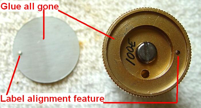
The tiny hole below the screw head is for accessing the calibration pot. Removing that screw lets you separate the knurled part of the element from the body:
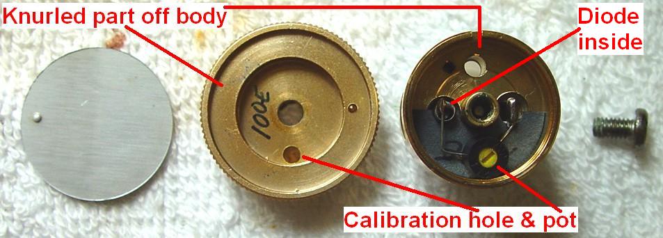
Here you can see the calibration pot and a thin fiber insulator below it that have been removed. The "100E" is the element's model number. I presume the "2/91" under the knob is the manufacture month and year. Note the recess inside the knurled knob to secure the pot:
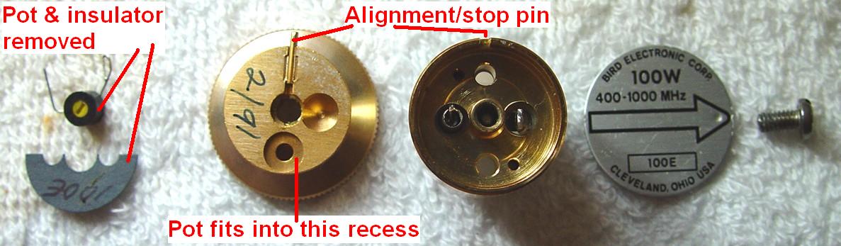
The terminal on the left is one end of the diode that connects to the sampling loop underneath. The terminal on the right connects to the meter contacts that barely protrude from the sides of the element body. The calibration pot measured 20.5k on this element, but only one end and the wiper are utilized. The pot is marked "25K" and is 7mm in diameter, what was once a common size. That's as deep as you can go from the top of the element.
Getting to the bottom of the element:
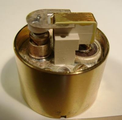
On some elements, there are screws that run through the two large holes in the body to hold the nylon piece to the bottom of the element, but not on this one. I saw nothing holding it in place. It was snug but it could be rotated. I suspect that on some elements, the screws hold it in place because the sampling loop needs to be held closer to the bottom of the element and in constant alignment. I tried gently prying mine off with a big pair of Channel-Lock pliers and some small screwdrivers. After doing this, the nylon was visibly deformed, so be careful when you try to get yours off. (I wonder if Bird would sell me a new nylon cover piece?) There may be a gentler method but I was in a hurry. Eventually it unsnapped from the body, revealing the sampling loop and other components, mounted to a disk:
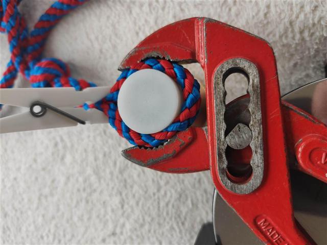
I received this tip from a reader in Bavaria:
When opening the slugs, I failed a few times, had dents in the caps, or damaged or broke
the caps. I found a solution for this problem that works perfectly for me. I take a rope
(not too small) to use with a pliers (water pump pliers in my case), between the cap and
the pliers, to prevent damage to the cap. I hold the plastic cap close to the metal element
and remove the cap by squeezing the pliers onto the rope, wiggling a little and finally
pull it off. No dents or deformation and it goes back on easily. See the photo below.
Bob VE3YX sent me these photos of a 10kw, 25-60 MHz element he took apart to repair. Notice the multi-turn sampling loop (coil). I suspect there is a variety of sampling loop designs.
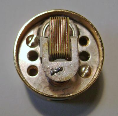 |  |
Two tiny screws hold this assembly to the body. On my element, neither of these screws was tight, and I suspect this was part of my problem:
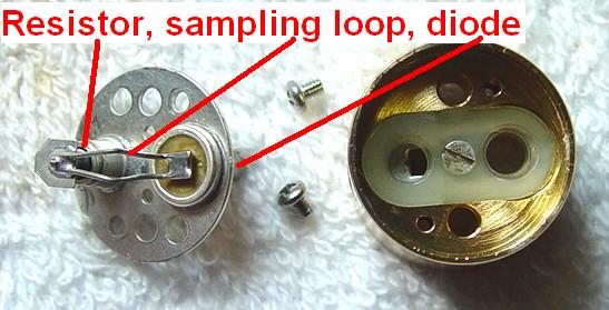
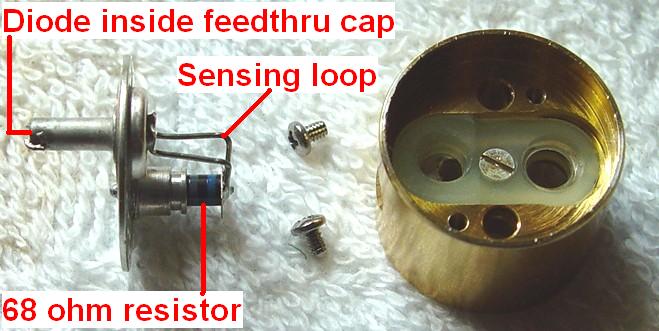
A side view shows the terminating resistor (color-coded 68, measured 72.9 ohms) at the bottom of the assembly, and what must be a diode at the top that fits inside the feed-thru tube that protrudes through the element body. The actual resistance doesn't seem to be critical, as the calibration pot can make up the difference. I've read that some elements used 1N21B crystal diodes, which were common as microwave mixers. The actual frequency-specific sampling loop connects the two:
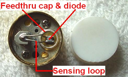
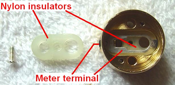
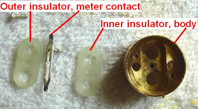
The feed-thru cap fits through the hole on the right side of the body and connects to one side of the calibration pot. The meter contact is sandwiched between two pieces of nylon held into the body by one screw. These must be assembled in a specific way. The two pieces are different and not symmetrical. Here's the outer one removed:
Here's the meter contact removed. Note the tarnished tips:
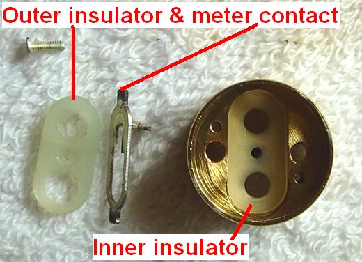
And finally here's the inner insulator removed:
That's it; no more parts. Other than the loose screws and tarnished meter contact (which I cleaned with some Tarn-X metal cleaner), I found nothing else wrong with the element.
Tarn-X may not do the job. You may need to use some abrasive material, such as fine steel wool and even emery cloth.
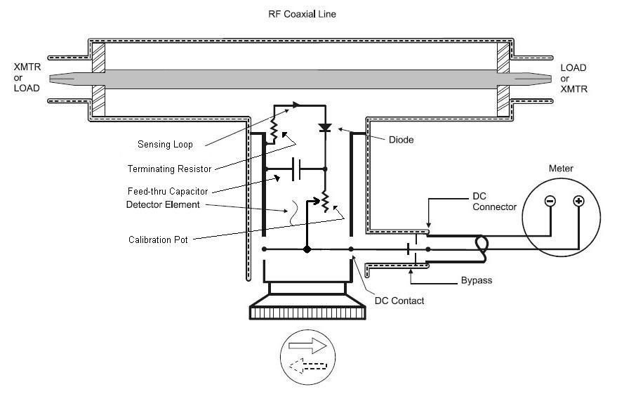
Here's a diagram of an element and the line section of a Bird 43 wattmeter, extracted from the Bird RF Directional Thruline Wattmeter instruction manual (I could find no copyright notice in their on-line PDF file). I've edited the image to show the 68 ohm terminating resistor, feed-thru capacitor, and calibration pot. Other elements may have a different circuit configuration:
Reassembly:
After cleaning the meter contact, I put the inner insulator, the contact, and the outer insulator back into the rear of the body and secured them with the screw. I made sure the contacts were centered in the side openings of the body - they were not when I first received the element.
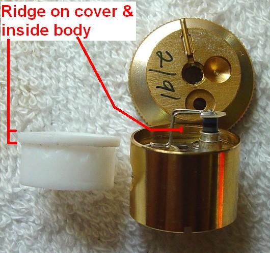
The sampling loop assembly is next. It can only go in one way and I made sure the two screws were quite tight. The solder connections looked perfect. I'm about to snap the nylon cover back onto the bottom of the body as we're done with this end of the element. Note that the ridge on the nylon cover snaps into the milled groove inside the body on this element:
We now turn our attention back to the top of the element. The fiber insulator goes on, then the calibration pot can be soldered back in place. I was careful not to disturb the leads when I removed it, so it went back exactly where it was originally. When putting the knurled knob back on, make sure the pot fits into the recess underneath the knob, and the locating pin fits into the slot in the body of the element up at the top. The adjustment slot of the pot will now be in the center of the hole in the knurled knob. Secure the knob to the body with the large screw. I think Bird uses some thread locker compound (often called Loctite) on this screw as I found some gray material on the threads and in the hole in the element body.
Final testing and calibration:
I still had the base station and my Bird 43 set up, so I carefully adjusted the station's output power to exactly 80 watts with the CDI element in the meter. Then I inserted the repaired Bird element and keyed the station. It read 84 watts and was quite stable. I used a small flat-blade alignment tool and adjusted the calibration pot in the Bird element so the meter read 80 watts. I found that the pot was noisy, so I rotated it back and forth several times to clean it, then I set it so the meter read 80 watts. I swapped elements several times to make sure nothing had changed. It now seems to be rock solid. Remember that most Bird elements have a specified accuracy of ±5% of the full-scale value, so for this element, that's ±5 watts. The photo below shows the setup with both meters, with the repaired Bird element in the Dielectric meter:
and with the repaired Bird element in the Bird meter:
I put a piece of double-sided cellophane tape (not the thick foam stuff) on the inside of the aluminum cover, carefully avoiding the dimple, and trimmed off the excess. I lined up the dimple in the cover with the dimple in the knurled knob and pushed the disk back into the element. I tried the element in the wattmeter once more and it's still working just fine. I'd probably suggest using rubber cement, some other kind of house-hold cement, or even a few small dabs of silicone sealant to hold the cover in place. You never know when you'll need to get into it again, so don't use anything permanent (like Super-Glue).
I suspect that the solvent may have removed a lacquer coating on the knurled knob piece, so I expect it will start to tarnish at some point. I will probably mask off the element body and spray some lacquer on the back and knurled edges of the knob.
The operation was a complete success. The patient lives on. I probably spent an hour taking it apart, taking photos, and reassembling it, as this was my first look inside a Bird element. This procedure saved me the shame of having to buy a brand new one.
11 years later (July 2017) the Sola wattmeter and 100w Bird element started acting up. It had erratic readings and when it did settle down, it was quite low, showing 20 watts when another element showed 60 watts. Swapping elements and meters around, I determined it was the 100w Bird element at fault. I took it partially apart but found everything nice and tight. I ended up just readjusting the calibration potientiometer, after rotating it end-to-end several times to clean it. If this element acts up again I will replace the pot.
In September 2017 I ended up replacing the pot. The original was not available anywhere so I chose another one: Digikey part number 3329H-1-253LF-ND listed as "TRIMMER 25K OHM 0.5W PC PIN" for $3.14. It fit right into the available space and was easily adjusted through the hole in the front of the element. It's also available from Mouser as part number 3329H-1-253LF.
By the way, additional information on the care and repair of Bird wattmeters and elements can be found on this web page at www.chuckmartin.com.
Other Element Variations:
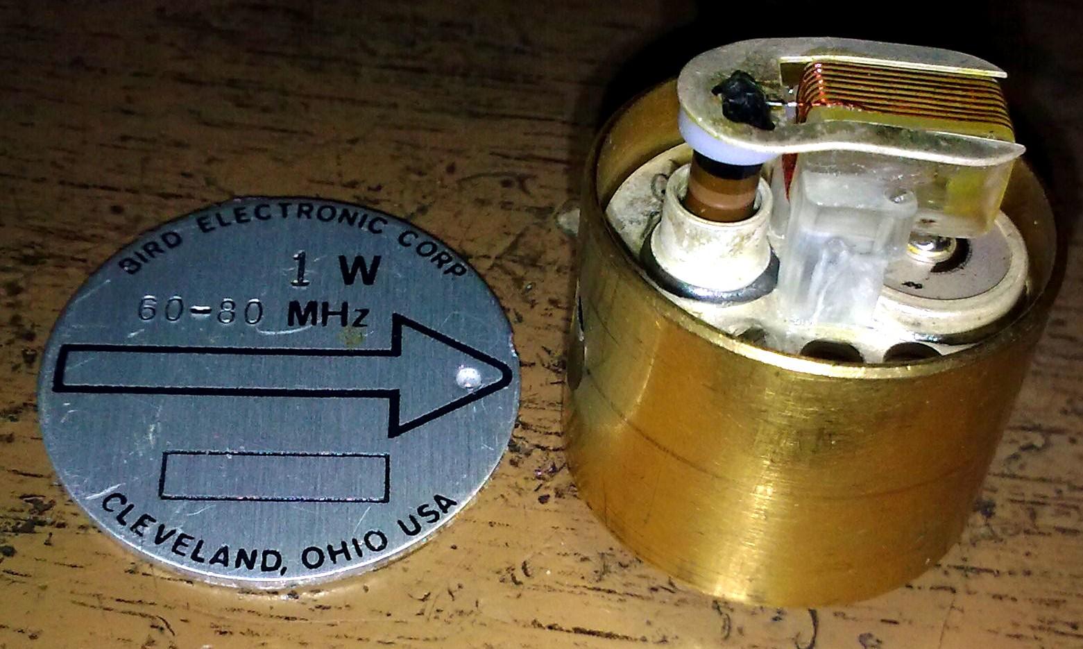
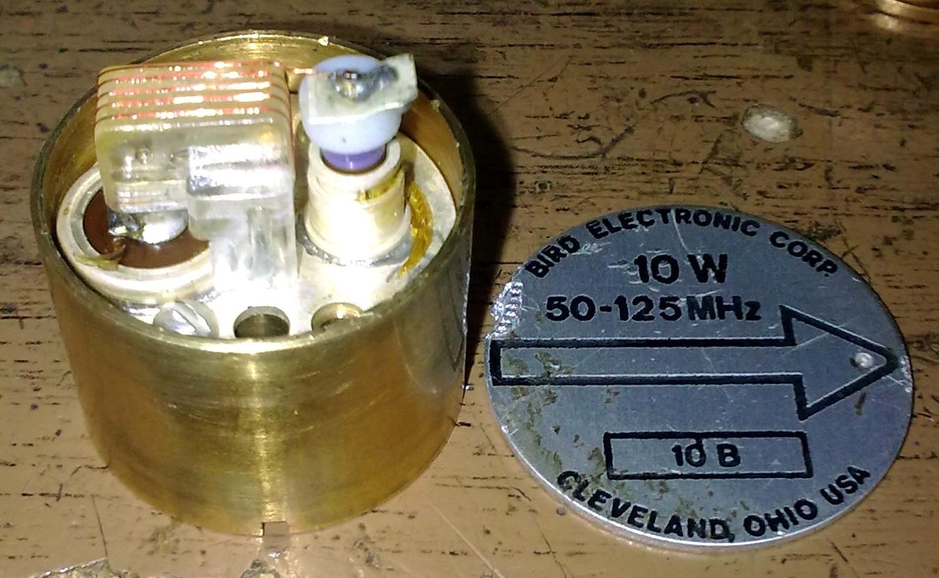
John OK1BAF provided the following element photos. They show the different sampling loops used by various power levels and frequency bands. Click on any photo for a larger view.
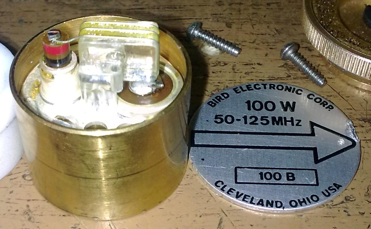
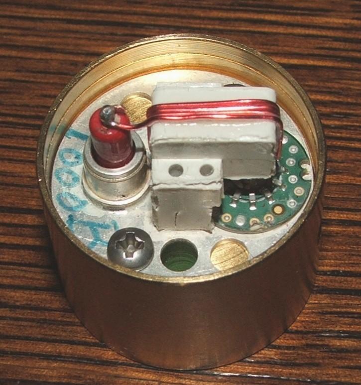
Tomas OK1DXD provided these photos of a new 1000 watt 50-125 MHz element that had a shorted diode. It seems Bird now uses a small circuit board to hold the few parts in place.

Acknowledgements and Credits:
Bird and Thruline are registered trademarks of Bird Electronic Corporation.
Sola Basic and Dielectric don't seem to be making wattmeters any more. This meter design was probably acquired by CDI, as it resembles their model 81000 rather closely.
Goof-Off, Channel-Lock, Tarn-X, Loctite, and Super-Glue are brand names and/or registered trademarks of their respective companies.
Photos of the 10kw, 25-60 MHz element were provided by Bob VE3YX.
Additional element photos were provided by John OK1BAF and Tomas OK1DXD.
This article was mentioned in the bi-weekly ARRL Contest Update newsletter, 20-Jan-2010 issue.
Contact Information:
The author can be contacted at: his-callsign [ at ] comcast [ dot ] net.
This page first posted in early June 2006.
Go to the top of this page
Up one level
Go to Home
Article text, photos (except where noted), and HTML © Copyright 2006 By Robert W. Meister WA1MIK
This web page, this web site, the information presented in and on its pages and in these modifications and conversions is © Copyrighted 1995 and (date of last update) by Kevin Custer W3KKC and multiple originating authors. All Rights Reserved, including that of paper and web publication elsewhere.