A Multi-Element Exposed
Dipole Array
6 or 9 dBd gain vertical for VHF
Original design by W2EWY & WB2ICP
Original article appeared in the ARRL FM & Repeaters
Manual.
Copyright 1978 American Radio Relay League, Inc.
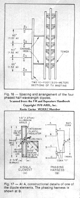
Description: The antenna described in this article and appearing in the image depicted in Figures 16 and 17 below was originally designed by W2EWY and WB2ICP, adapting some of the more attractive features of commercial arrays. Excellent results have been obtained with this design as it features four closed ½ wave grounded dipoles fed in phase.
Concept of construction:
Basically, the antenna consists of four stacked, grounded, half wave dipoles fed off center, providing a 6 dB gain when configured omnidirectional or 9 dB with an offset pattern. Gain figures are referenced over a dipole. This antenna was designed for the amateur 2 meter band.
One problem in antenna installations is static type noise. The grounded dipole configuration has the advantage of reducing this type of noise appreciably.
Figure 16 shows the spacing and arrangement of the dipoles on the supporting mast.
Figure 17A shows the details for one of the elements. The two sides and ends of the elements are made from ½ inch aluminum angle stock, available in 8 foot lengths from many hardware stores. A single 8 foot section will make one element. The element supports are also made from the same type of angle stock.
Figure 17B shows the details of the phasing harness which is made from copper shield type RG-59/U. Lengths A, B, C, and D are 40.8 inches (1.04 meters) long from the dipole feed to the center of the T. Lengths E and F are 63.8 inches (1.62 meters) long from T center to T center. Copper type RG-59/U is required because you cannot solder to modern aluminum CATV types. RG-11/U (copper shield type, sometimes referred to as RG-11A) could also be used as a replacement for the RG-59/U. Make sure solid dielectric (not foam) is used or the velocity factor will need corrected.
The feeder connection appearing at G is 50 ohms and can be any length desired for connection to the radio equipment and hardline type coaxial cable is normally used for the feeder run in repeater service. The harness is attached to the supporting mast in several places using quality electrical tape like Scotch 33 Plus or equivalent. It is a good idea to use quality heatshrink or many layers of electrical tape on the T connections to prevent water ingress. After complete assembly, the bays and connections to them can be sprayed with clear Krylon to help prevent water damage.
If the four elements are mounted in line on the mast section, the pattern will be offset with a null appearing in the direction of the supporting mast. The four dipoles can be positioned around the mast to provide an omnidirectional pattern. No matching is needed with this type of antenna. Of several units built from the specifications given, the SWR was below 1.2:1.
[HTML Editors note:] Although no power handling capability was mentioned in the original article, I feel the array will handle 250 watts continuously if RG-59/U is used in constructing the harness, or 500 watts if RG-11/A is used.

Original Copyright © 1978 ARRL. Inc. and originating authors.
All Rights Reserved.
HTML Copyright © Thursday, January 11 2001 @ 11:04 PM
Kevin Custer W3KKC All Rights Reserved.