StarTech CM108 based USB Sound Adapter modification
to USB Radio Interface
For AllStar - Asterisk - app_rpt
By Kevin Custer - W3KKC
The StarTech USB FOB is possibly the most readily obtainable and reasonably priced C-Media
CM108 based USB sound adapter in the USA.
The device is mostly surface mount, but, depending on your skill level can be modified
into an inexpensive USB radio interface.
The instructions provided here will help with the modification of this device to bring
out PTT, Main and Aux TX Audio, Receiver audio with variable input control,
and
diode protected COS and CTCSS (PL) hardware inputs.
The construction practice I chose makes use of a square piece of unetched printed circuit board.
I made "islands" from 1/4" pieces
of board that were super-glued to the main board.
These islands make insulated pads to solder to. Since there
are only nine
support components, this technique is simpler than etching a PC board.
Please read the entire article before starting this conversion - as it's fairly involved!
|
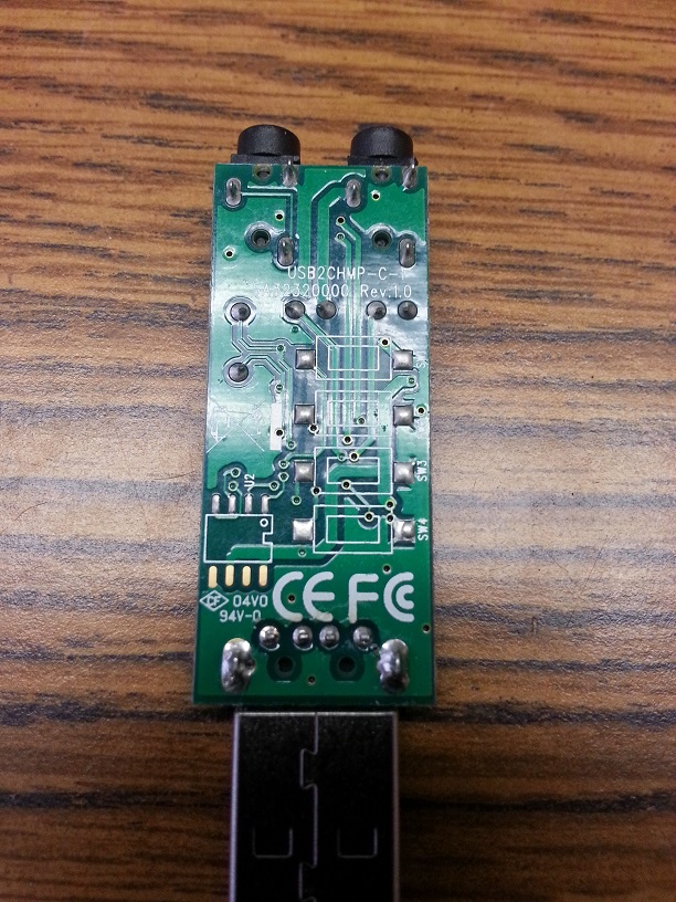
Below - Photo 1 - Unmodified StarTech USB sound FOB.
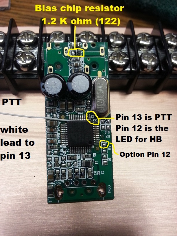
Below - Photo 2 - Detail of bias resistor location and PTT connection to CM108 pin 13.
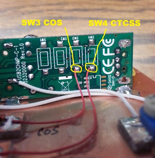
Below - Photo 3 - Detail of COS and CTCSS (PL) hardware connection.
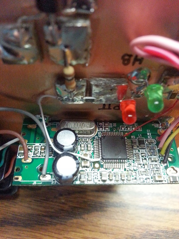
Below - Photo 4 - Detail of CM108 pin 12 Heartbeat LED source lead connection.
Below - Photo 5 - Modified unit built on double sided PC board with added components.
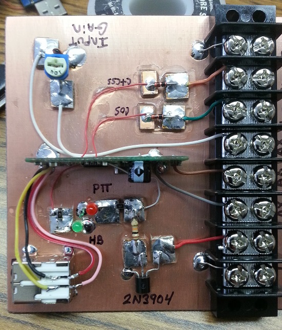
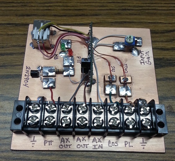
Below - Photo 6 - Another shot of finished unit showing terminal connections.
Concept:
The article presented here was the result of modifying a StarTech ICUSBAUDIO
sound FOB for Chuck Kelsey - WB2EDV. Chuck ordered this FOB from
NewEgg
but after opening it decided against modifying it on his own. Chuck told me about
his purchase and subsequent decision, and I offered to do the modification. The
concept outlined here is a bit different from other modifications for similar devices,
but since this is going to be used in conjunction with learning about Asterisk, app_rpt,
and the different distributions of the software, I felt it was the best approach.
It allows for easy connection to the radio using a screw terminal strip.
I added two LED's to show the "heartbeat" and PTT status, as this particular FOB doesn't
include any LED indicators as supplied.
There are two different board revisions that I know of.
The one shown here is likely the later revision - it has a 90°
trace that connects the tip to the ring on the MIC jack. See the upper left corner
of the PC board in Photo 1. The other (earlier) board revision doesn't have this trace,
and some instructions on the Internet favor this board for conversion. Either version
is suitable for conversion and neither is better than the other.
Some instructions claim it's necessary to cut
this 90° trace, but, as I explain later, there are other options.
After doing some research on this particular product, which included reading most of reviews
on the NewEgg site, I conclude the earlier version of this board used a stereo audio jack for
the microphone, but, the circuit board didn't provide bias to the ring. Most headset
combos now come with a 3 conductor (Stereo, Tip, Ring, Sleeve - TRS) microphone plug - even
though the microphone is monophonic. This arrangenment allows the headset microphone
to be used with an audio adapter that has a true stereo input. I suspect StarTech received
complaints from those wanting to use a headset with a stereo plug, and because of the way it
was wired, resulted in no microphone audio. The fix was to connect the tip to the ring.
The 90° circuit trace on the later board revision does exactly that.
Conversion:
Start the conversion by carefully opening the device. Be careful that you don't cut
yourself or run a jewlers screwdriver through your hand. This process is much like opening
a clam shell - using a pocket knife or small screwdriver with caution. It might be helpful
to grasp one half of the case in a small vice. Also, be careful not to ram the knife or
whatever into the interior of the unit, otherwise damage to the PC board or components can result.
After opening the shell, you can see which board version you have.
Remove the USB connector from the FOB. It will be replaced with a USB "B" socket
connector soldered to the PC board ground plane.
I chose to remove the audio jacks since I wasn't going to use them to connect to the audio.
This opens up the board and allows for easy removal of the bias resistor. This
chip resistor (R10 - 1.2k ohm) normally supplies voltage to the electret condenser microphone.
These microphones have an internal audio amplifier which requires voltage to operate.
The removal of this resistor does two things: First, it removes the voltage on this
lead eliminating the need for another coupling capacitor. Secondly, it raises the input
impedance from 1.2k to the value of the input control potentiometer - 100k ohms.
See Photo 2 for a detail of the location of this resistor. You'll notice I chose to
"tombstone" this component which effectively removes it from the circuit but holds its placement
if you ever want to reinstall it for some reason. Photo 4 shows another angle.
You can simply wipe it completely off the board if you choose. Removing
the resistor eliminates the need to cut the 90° (L shaped) trace.
If you choose not to remove the audio jacks and bias resistor, you'll need to cut the 90°
(L shaped) trace, and be sure to connect audio to the microphone connection more toward the
center of the circuit board. This effectively does the same thing as removing the bias
resistor, as long as you connect it up correctly.
The next step makes connection to pin 13 on the CM108. This pin is what produces the
Push To Talk (PTT) signal, but, it needs to be buffered with a transistor so it can sink enough
current to be compatible with most transmitters. This step is one of the most difficult,
as soldering to one of the 48 pins of the chip, without shorting something out, can prove
to be difficult. To make this connection, I use "Kynar" wire. This is a 30
AWG 'wire wrap' wire. Since the connection is on a end (corner) conductor, and because
there is enough space to slide the insulated wire underneath the complete row of 12 pins,
this process makes an easier time of it. Sliding the wire under the pins holds it
in place while soldering. I begin by stripping about 1/16" of insulation from a 4"
piece of wire and sliding it in from the opposite end. Then, with the end of the
insulation lined up with the very end of the pin, bend the wire conductor over so it lays
beside the pin and carefully solder.
If you would like to add a "heartbeat" LED,
do the same thing only this time connecting to pin 12, which is also on a corner.
Refer to Photos 2 and 4 for detail on routing these wires under the pins of the chip.
Optionally, pads are included on the board for a surface mount resistor and LED that would
provide this heartbeat indicator on the board. These pads are marked
R11 and D1. The appropriate surface mount components could be soldered to
these pads with slightly less difficulty than soldering to Pin 12. Easier yet, a
wire can be soldered to the pad for R11 which is furthest away from D1. This pad
connects directly to CM108 Pin 12. Photo 2 shows this option connection.
If you care to use the 'hardware' COS and CTCSS (PL) inputs, you'll need to solder
wires to pads that were originally designed to accomodate push-button switches - but
they were not installed on this model. Photo 3 details these connections.
These inputs are protected by a series Shottky diode. I soldered two 3"
wires to the pads. These inputs can be either logic high or low depending on the
settings in the urd, usbradio, or simpleusb conf. files.
Finish the FOB conversion by soldering 4" wires to the Left and Right audio outputs, and
MIC input. These connections are outlined in the schematic diagram, and are connected
in holes left by removing the two audio jacks. Photo 4 shows a gray and brown wire - these
are Left and Right outputs respectively. The MIC wire can go into either hole of
the 90° trace, if you removed the bias resistor, otherwise it'll need to go into the
hole closest the center of the board, as shown in Photo 3 - the white wire. The other ends
of these wires will connect to circuit pads or terminal screws. I used super-glue to attach
the terminal strip to the PC board. Then, solder the FOB onto the PC board. This is
accomplished by scraping away some of the solder mask from the ground plane of the FOB's circuit
board. This is done on the edge closest the crystal - both top and bottom sides near
the outside edges. See Photo 3 and 4 for detail.
Refer to the Photos 5 and 6 for positioning of the circuit pads. Exact location
is of little importance. Since this project is built on a hefty ground plane,
there is little chance of hum or noise problems due to part placement. I used
a mix of surface mount and leaded components. Use whatever you have or are comfortable
with. Trim the wire leads to their proper length, cutting off any excess. One
component that can be readily damaged due to improper hookup is the 2N3904 NPN
transistor. With the circuit pads as large as I made, just about anyone could change
this transistor with minimal soldering skill. Remember, connection anywhere on the ground
plane of the PC board allows for a ground connection. I soldered the emitter of the
transistor, minus connection of the LED's, cold leg of the potentiometer, USB "B" connector body,
and both end terminals of the terminal strip directly to the board. Finish by connecting up
the terminal strip and USB connector with more wire. A drop or two of super-glue can be
used to hold the wires in place - if routed close enough to the PC board.
Parts List:
2 - BAT43 (or equivalent) Schottky diodes.
1 - 100K ohm potentiometer - Radio Shack 271-284
1 - 47 pF ceramic disc capacitor.
1 - Green LED.
1 - Red LED.
2 - 330 to 470 ohm 1/8 or 1/4 W resistors - for feeding the LED's.
1 - 10K ohm 1/4 W resistor - for transistor bias.
1 - 2N3904, 2N2222 or equivalent NPN switching transistor.
1 - USB "B" chassis socket connector.
1 - 8 position Radio Shack barrier terminal strip 274-670
3.75 inch square piece of double or single sided PC board.
Several 1/4 inch square pieces of board for island pads.
Super Glue
1 - USB "A" to USB "B" cable - 24 inches long or so.
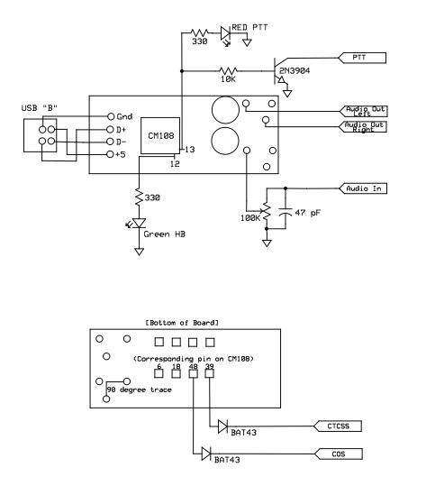
Below - Schematic diagram - click on image to download printable PDF.
I hope you have enjoyed this article.
73,
Kevin Custer - W3KKC
Email
Kevin Custer - W3KKC for email support of this modification.
Article by Kevin Custer - W3KKC, all rights reserved.
Schematic image and PDF courtesy of Chuck Kelsey - WB2EDV
Specifications may change without notice.
Copyright 2014, Kevin Custer - W3KKC.
Photos property of Kevin Custer - W3KKC.
HTML January 5, 2014, W3KKC - All Rights Reserved!
Optional pin 12 connection suggestion provided by Thor Wiegman - N7JCT
This web page, this web site, the information presented in and on
its pages and in these modifications and conversions is © Copyrighted
1995 and (date of last update) by Kevin Custer W3KKC. All Rights Reserved, including that of paper
and web publication elsewhere.