This circuit was designed by my father, Ken Custer W3WGX in the 70's, and appeard in some trade magazines.
Copyright© 1995 to present Kevin Custer W3KKC
Concept & Description: Did
you ever want a simple controller to key a transmitter from a receiver's
cos?
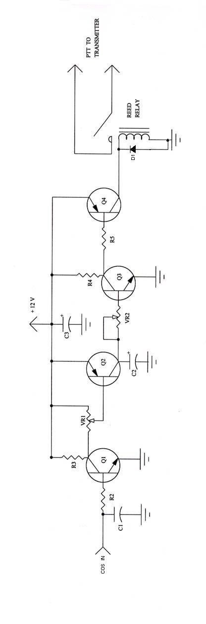
Well here is a simple circuit that does just that. The input
impedance is fairly high, about 1 Meg, and will interface to most any receiver.
VR 1 is a sensitivity control that is adjusted to trigger the circuit with
just about any available positive going signal. A setable hang time is
adjusted with VR 2.
Construction: Construction can be simple breadboard wiring, as the circuit is simple. A reed relay is used for two reasons. First, the time delay, in this circuit, is provided by charging and discharging a capacitor, and connecting the output directly to the transmitter will provide a voltage that does not snap between on and off, thus the characteristics of the relay are desirable. Second, interfacing the relay is simple, simply connect one contact of the relay to either ground or voltage depending on the signal needed to key your transmitter. I have used this circuit in several systems for years with no relay failure ever. Radio Shack sells good quality reed relays. VR 1 is a sensitivity control. VR 2 sets the time delay, and is used in conjunction with C2. C2 can be changed up in value to provide longer delay time, or lessened in value to do the same in time.
Parts List:
Q1 & Q3, 2N2222 or equivalent.
Q2 & Q4, 2N3906 or equivalent.
D1, 1N914 or equivalent.
R1 NOT USED
R2, 1 Megohm
R3, 47 Kohm
R4, 10 Kohm
R5, 2.2 Kohm
VR 1 & VR 2, 47 Kohm pot.
C1, 100 pF disc ceramic.
C2, 4.7 uF tantalum 35V.
C3, 100 uF or larger 35V electrolytic cap.
Reed relay, 12 volt reed relay.
This circuit was designed by my father, Ken Custer W3WGX in the 70's,
and appeard in some trade magazines.
Copyright© 1995 to present Kevin Custer W3KKC