Back to Home
by Robert W. Meister WA1MIK

|
Up one level Back to Home |
Kenwood COR PTT Buffer Circuit by Robert W. Meister WA1MIK |
|
Background:
John W1GPO was trying to use a Kenwood TK-8180 UHF mobile radio as a link transceiver to interconnect two six-meter repeaters (the TK-7180 is the identical VHF unit). He had already configured one of the Auxiliary I/O pins on the radio's DB-25 Accessory connector to go low when a properly coded signal was received. He needed this signal to activate the PTT line on his Micor repeater. Unfortunately the Kenwood radio has diode clamps on all of the I/O pins on the DB-25 connector, which limits the voltage between 0V and 5V, and the Micor PTT input rests at nearly 12V. As soon as he connected the two, the Micor repeater keyed up. Even worse, when he turned the mobile radio off, all of those I/O pins were pulled to ground, which also keyed the Micor repeater.
He tried putting some zener diodes in series with the I/O pin and the Micor PTT line, and while that at least prevented key-up when the radio was idle, it didn't key the Micor when a properly coded signal was received by the Kenwood radio. He discussed his requirements and problems with me and I designed the circuit below.
While this was specifically made for the Kenwood TK-7180 / TK-8180, it should work equally well with other brands and models that have an active-low COR signal that needs to activate a PTT line that exceeds +5V.
Signal Requirements:
The Kenwood Kenwood TK-7180 / TK-8180 accessory connector signal AUXIO9 (pin 4) is just one of several general-purpose input/output pins that can be assigned to a specific function by the radio programming software. These signals are active-low and have a 47k pull-up resistor to +5V. These signals are also limited by a diode going to ground and a diode going to the +5V supply, so they can't go lower than about -0.7V or higher than about +5.7V. When active, the pins go low to about 0.3V. When the radio is turned off, the 5V supply goes to ground and anything connected to it (those limiting diodes and pull-up resistors) will be pulled to ground.
The +5V power source is NOT present on the accessory connector, however switched B+ (i.e. +12V) at up to 2 Amps is available and this is only present when the radio is turned on and operational.
The Micor repeater is completely solid-state and uses no relays. The "Line PTT" input is pulled up to +12V and must go significantly below +4V to key the station. In normal use, a local microphone would ground the PTT line when transmission is required. The best thing to key the station would be a dry relay contact or an open-collector transistor to ground.
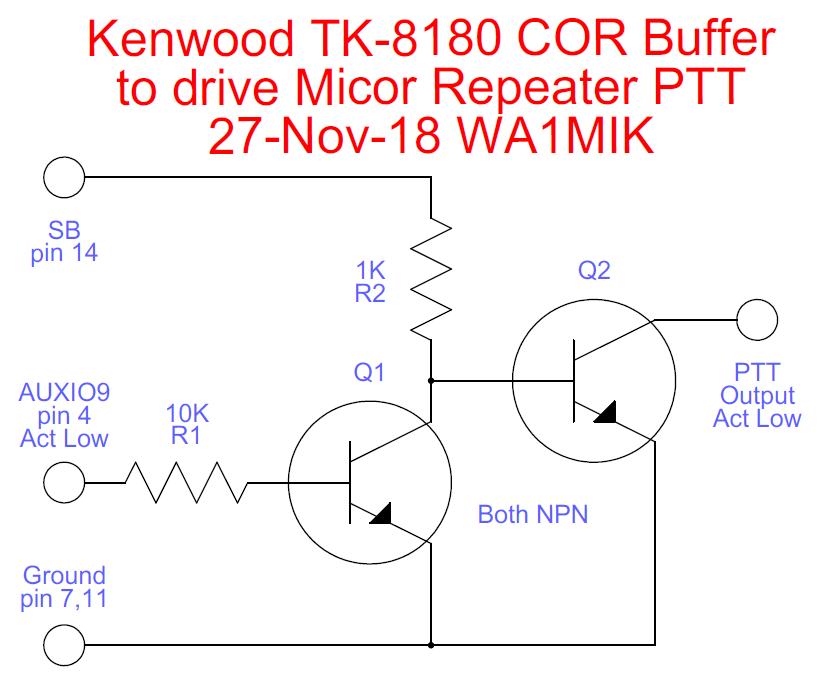
Circuit Description:
The incoming signal from the Kenwood AUXIO9 (pin 4) signal sits at +5V with no RF signal. (It appears that the radio actually pulls this pin high with a transistor.) This high level goes through R1 and turns on Q1. The collector of Q1 goes low and keeps Q2 turned off. The (open) collector of Q2 can go wherever it wants, as it connects to the Micor PTT input, which sits at +12V. Both transistors are common NPN small-signal variety such as 2N2222, 2N3904 or equivalent, good for about 200mA collector current.
When an incoming and properly coded RF signal is present, the Kenwood AUXIO9 (pin 4) drops to around 0.3V. This low level goes through R1 and turns off Q1. The collector of Q1 is pulled up through R2 to +12V via the radio's SB (pin 14) signal, but it can only go up to about 0.7V, as Q2's base-emitter junction limits the voltage. This turns on Q2 and its collector then drops to around 0.3V (ground), which will key the Micor repeater, causing it to transmit. R2 is a low value to provide adequate base current to Q2, so that it can sink a high PTT current to ground, if necessary (for example, driving a PTT relay coil).
If the Kenwood radio is turned off or should lose power, there is no pull-up voltage feeding R2 (in fact, R2 is pulled to ground), so nothing can turn on Q2 and the repeater won't be keyed up. Refer to the schematic below.
Contact Information:
The author can be contacted at: his-callsign [ at ] comcast [ dot ] net.
Back to the top of the page
Up one level (Project Index)
Back to Home
This page created on 30-Nov-2018.
Article text © Copyright 2018 by Robert W. Meister WA1MIK.
This web page, this web site, the information presented in and on its pages and in these modifications and conversions is © Copyrighted 1995 and (date of last update) by Kevin Custer W3KKC and multiple originating authors. All Rights Reserved, including that of paper and web publication elsewhere.