Back to Home
Base Station
Test Meter
By Robert W. Meister WA1MIK

|
Up one level Back to Home |
Motorola Motrac Base Station Test Meter By Robert W. Meister WA1MIK |
|
What I Needed and Why:
I acquired a 1974-vintage, Motorola low-band Compa-station, model C74LHB3100CR. This is a single-frequency, 100 watt, DC-remote base station that uses a Motrac mobile radio internally. It has a solid-state receiver and exciter, and a tube driver and tube final. It is presently on 26.31 MHz and has full PL. It already handles the 25-30 MHz split and I plan to move it to the 10-meter FM band.
In order to tune and align this radio, a Motorola test set is usually required. It uses radio-specific cables that mate with the oddball 12-pin metering connectors. The test set consists basically of a 50µADC meter and a selector switch. Depending on which unit you're working with, you must plug the metering cable into the metering socket on the receiver or transmitter. There's also a metering socket on the remote control chassis, but I didn't worry about that.
I already had an official Motorola 50µADC meter from a long time ago (in my tube radio days) and I knew I needed to buy the unique connector to plug into the socket; I'd buy the remaining parts as needed.
This is a purpose-built metering test set. It was designed to work only with the station I had (low-band Motrac). You can adapt the ideas presented here to make a similar test set for just about any station. I make no promise as to the usefulness or adaptability of this project to your own needs. Additional information about test sets can be found on the Repeater-Builder Portable Test Set page by clicking here.
Metering Requirements:
The individual transmit and receive metering sockets are documented below, taken from their respective schematics. Click on any of the photos or images for larger views.
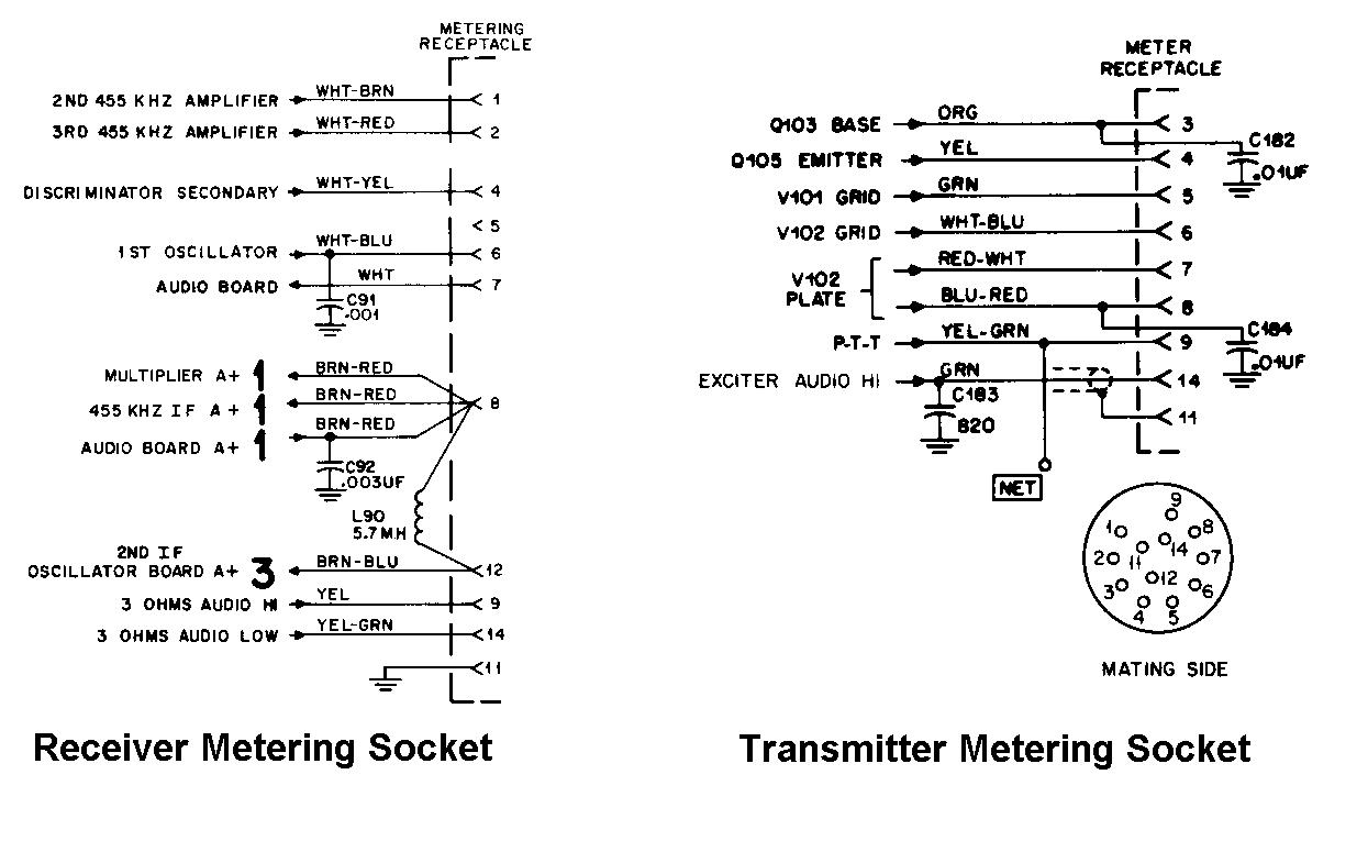
The manual for the Compa-station was very complete. It even contained schematics of two metering setups. Here's one:
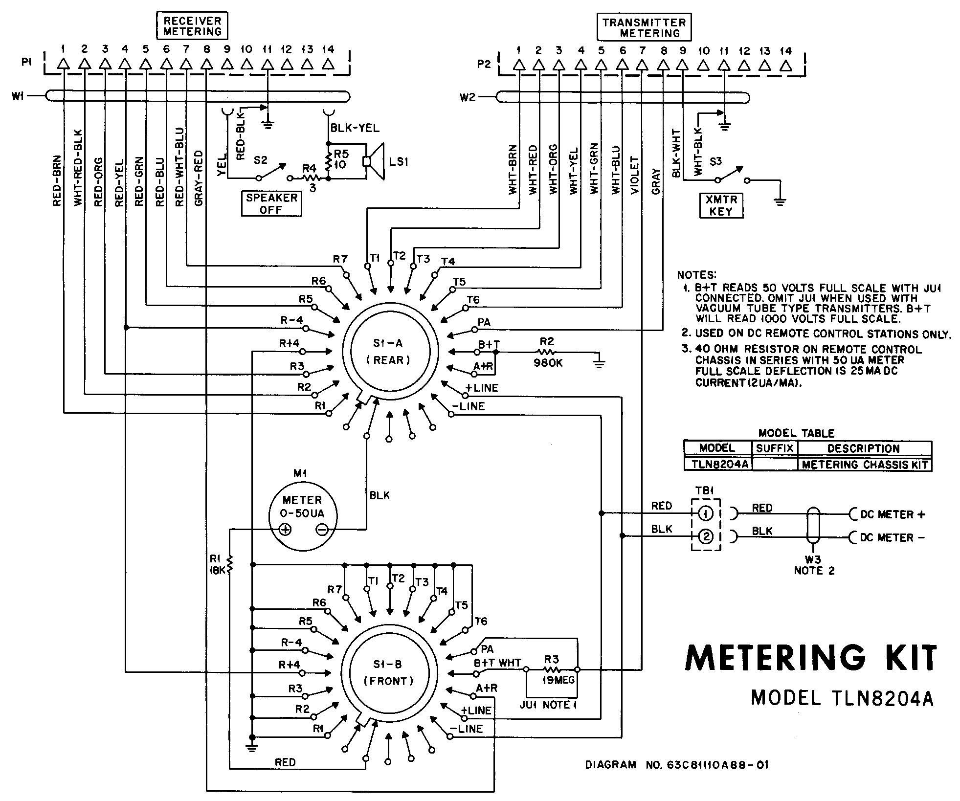
This one uses two metering plugs, a 24-position rotary switch, and a handful of resistors. At almost $20 each, I didn't want to buy two new metering plugs from Motorola, so I sat down and summarized the requirements. All signals use ground reference unless otherwise noted.
| Pin | RX Use | TX Use |
|---|---|---|
| 1 | 1st IF | - - - - - |
| 2 | 2nd IF | - - - - - |
| 3 | - - - - - | Mult. |
| 4 | Discr. [1] | Doubler |
| 5 | - - - - - | Drvr Grid |
| 6 | Mult. | PA Grid |
| 7 | - - - - - | B+ (800V) |
| 8 | A+ (13V) | PA Cur [2] |
| 9 | - - - - - | - - - - - |
| 11 | Ground | Ground |
| 12 | - - - - - | - - - - - |
| 14 | - - - - - | - - - - - |
NOTES:
[1]: Discriminator polarity reversible.
[2]: PA Current referenced to B+ (positive).
The resistors in the test set allow the meter to have three scales. The bare meter with the 18k resistor in series is used for most tuning, using a 0-50µA scale. This also makes it a 1V full-scale, 20,000 ohms-per-volt meter; when put across the 2 ohm PA Current resistor in the transmitter, the meter indicates 500mA full-scale for plate current. With the other two resistors, the meter indicates 1000V full scale for plate voltage.
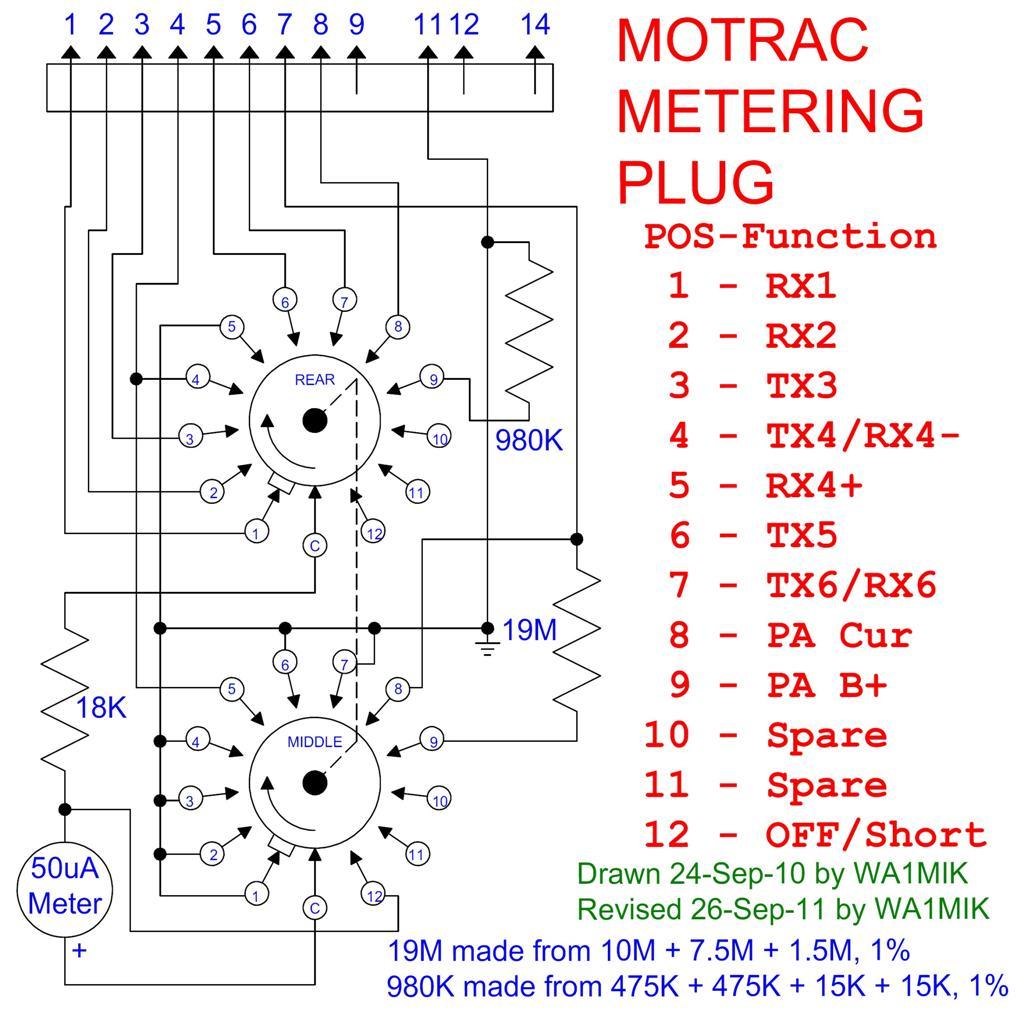
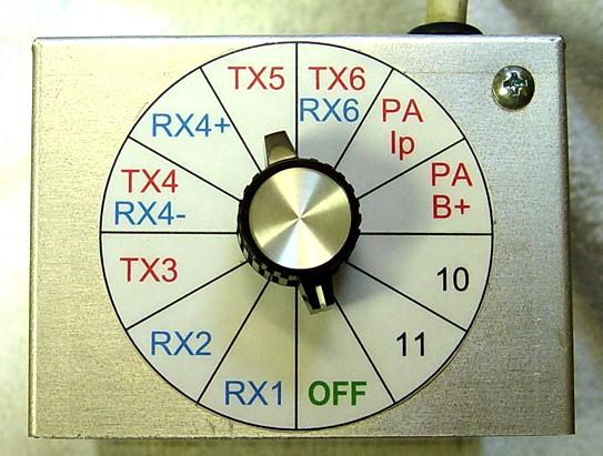
I decided I could simplify things and use a more plentiful 12-position rotary switch. I found a 3-deck, 12-position switch at a surplus supplier and bought a nice pointer knob for it. Here's the configuration table I came up with. Note also that position 5 will be reverse-polarity for TX4 and should not be used.
| Pos# | Neg- | Pos+ | Use |
|---|---|---|---|
| 1 | 11 | 1 | RX1 |
| 2 | 11 | 2 | RX2 |
| 3 | 11 | 3 | TX3 |
| 4 | 11 | 4 | TX4/RX4- |
| 5 | 4 | 11 | RX4+ |
| 6 | 11 | 5 | TX5 |
| 7 | 11 | 6 | TX6/RX6 |
| 8 | 8 | 7 | PA Cur |
| 9 | RES | 7 | PA B+ |
| 10 | Spare | ||
| 11 | Spare | ||
| 12 | OFF/Short |
Here's the schematic I developed for this test meter.
Parts:
All the parts except the metering plug probably cost me $30. I bought everything from Mouser, unless otherwise indicated. It took several hours to build.
Wire and Pin Assignments:
Of course, your wiring list and colors may be different from mine, depending on the cable you use. Note that there is no pin 10 or pin 13 on the metering socket or connector. The metering socket probably started life as a 9-pin miniature tube socket then they added four more pins in the center. I've seen tubes and relays that have 13 pins on them that fit similar sockets.
| Pin# | Main | Stripe |
|---|---|---|
| 1 | Brown | |
| 1 | Brown | White |
| 2 | Red | |
| 2 | Red | White |
| 3 | Orange | |
| 3 | Orange | White |
| 4 | Yellow | |
| 4 | Yellow | Black |
| 5 | Green | |
| 5 | Green | White |
| 6 | Blue | |
| 6 | Blue | White |
| 7 | Violet | |
| 7 | Violet | White |
| 8 | Gray | |
| 8 | Gray | Black |
| 9 | Pink | |
| 9 | Pink | Black |
| 11 | Green | Black |
| 11 | Shield | |
| 12 | Teal | |
| 12 | White | |
| 14 | Orange | Black |
| 14 | Red | Black |
| Sp | Black | |
| Sp | Black | White |
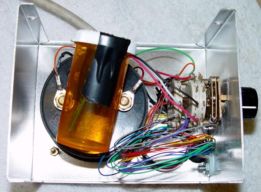
The Finished Product:
Well, it's almost finished. It probably needs a label on the front, and ideally I should have painted it before making it. That'll be hard to do now that the cable goes through the front.
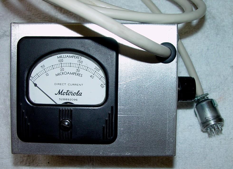
I labeled the rotary switch with a drawing from a CADD program. I laminated the paper with clear packing tape, cut it out, and affixed it to the side of the box with double-sided tape.
There isn't much to see inside except some wiring. I put all the metering resistors on a piece of perforated board and stuck that inside an old plastic pill bottle, taped it shut, and positioned it inside the box. It should have been mounted somewhere but I couldn't come up with a clean way to do that. As there's 800 volts on these resistors when the metering cable is plugged into the transmitter, the pill bottle gives me adequate insulation and protection. Of course the exposed switch terminals still need to be avoided.
The meter worked perfectly as soon as I finished assembling it. It allowed me to properly tune the transmitter, dipping the plate current and peaking all the other stages. After testing and using the meter, I finally soldered the plug shell to the connector body, thus sealing it the way it was meant to be.
Initially I had position 12 wired to ground on each deck; this did not fully short out the meter as it left the 18k resistor in the circuit. I rewired position 12 to completely short out the meter movement; this change is present in my schematic diagram.
Contact Information:
The author can be contacted at: his-callsign [ at ] comcast [ dot ] net.
This page created 25-Sep-2011.
Go to the top of this page
Up one level
Go to Home
Article text, layout, photos, and HTML © Copyright 2011 By Robert W. Meister WA1MIK
This web page, this web site, the information presented in and on its pages and in these modifications and conversions is © Copyrighted 1995 and (date of last update) by Kevin Custer W3KKC and multiple originating authors. All Rights Reserved, including that of paper and web publication elsewhere.