Limitations:
This simple voter has some limitations. For the money you will
spend on the voter, it will be the cheapest piece in the voting network
to implement. After you see the advantages of voting, this voter
may not be sufficient to handle your needs.
Go Here to read some additional notes.
Changing Levels and Part Availability:
After building and implementing several of these boards in real life,
I had a problem with levels not staying put. Others have commented
about having this problem. To solve the problem, I replaced the cheap
2/3 turn pots with quality multi turn units like the Bourns Trim Pot.
After replacing the pots, the level changing problem went away and hasn't
returned.
Bourns Trimmer Potentiometer 100K available from Digikey
Corp.
Digikey part number 3299Y-104-ND $2.92 ea.
Use these for R1, R2, and R3.
Bourns Trimmer Potentiometer 10K available from Digikey
Corp.
Digikey part number 3299Y-103-ND $2.92 ea.
Use this for R4.
The Op-Amp is available from Mouser Electronics
in the form of a substitute in the NTE7141 (Mouser P/N 526-NTE7141) at $3.60 each.
American Microsemiconductor still has the
CA3240E at just $1.10 each, but their minimum order is $35.00.
COS Considerations:
Mark Kolber's original design is to be used with negative logic signaling.
This is uncommon in most modern ham and commercial receivers and controllers.
If you need positive logic signaling, the addition of the simple circuitry
suggested below will aide in connecting the voter to positive logic equipment.
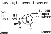
This circuit will allow a positive logic COS (+ voltage when receiving
a signal) to be connected to the voters inputs.
Two of these circuits may need constructed if both receivers employed
use positive logic.
Q1 is a 2N2222 NPN or equivalent.
R1 is a 10 K ohm resistor.
R2 is a 47 K to 100 K ohm resistor.

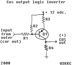
If positive logic is needed to drive a controller from the output of the voter, you have a choice. You can eliminate Q1 & R39 on the voter, and positive logic is available at the intersection of the 2, 10 K resistors (R37, and R38.) One could simply not install Q1 & R39 and just place a jumper between the base and collector pads on the PC board. This will connect positive logic to J6, the COR output. One problem, however, is the output capability is limited because of the 10 K resistors. So, if you rather not modify the circuitry on the voter board, or if you need more current driving capability, build the voter as suggested in the article and construct the circuit below.
This circuit will produce a positive logic output from the voter, (+
voltage when receiving a signal.)
Q1 is a 2N3906 PNP or equivalent.
R1 is a 1 K ohm resistor.
R2 is a 100 K resistor.
R3 is a 100 ohm resistor.
R4 is a 10 K resistor.
[ R3 is used as a current limiter in case the output
is shorted.. the transistor won't blow, it can be changed in value, or
eliminated ]
Don't go higher than 5 K on R3, unless R4 is eliminated
or changed up in value.

Operational Considerations:
Mr. Kolber's original design uses a long time constant for the averaging
of the rectified voltage produced by the users signal.
I have found that a shorter time constant was nicer, and more pleasing
to me. If the timing of the voter doesn't suit you, you can change
the time constant by changing the value of the filter capacitors C10 &
C11. Both should be changed to identical units.
I have found that 33 uF tantalum capacitors made the voter more pleasing
to me. This value can be tailored to suit your need.
Hope this helps.
Comments welcome.
Kevin Custer W3KKC
html January 2000