Up one level
Back to Home
|
|
Modifying a Radio Shack
Model #12-251 Weather Radio for
Connection to a Repeater
Controller
Photos and text by M. Scott Zimmerman N3XCC
HTML'd and edited by Mike Morris WA6ILQ
|
|

|
Note from WA6ILQ:
This modification is NOT controller specific. As long as your controller has an audio
input, has digital inputs that can sense a contact closure to ground, and can control
a relay coil, it will work. As an aside, if you needed to bring out both leads of each
relay coil there is no reason that you could not use a DA-15 connector.
The National Weather Service uses a technique called SAME - Specific Area Message
Encoding to direct local weather alerts to specific geographic areas. The Radio Shack
12-249, 12-250 and 12-251 receivers decode this "area code" and provide audio alerts.
More information can be acquired from the NWS web page(s) at
http://www.nws.noaa.gov/nwr/index.php,
especially at
http://www.nws.noaa.gov/nwr/info/nwrsame.html.
The SAME code tables are at
http://www.nws.noaa.gov/nwr/coverage/county_coverage.html
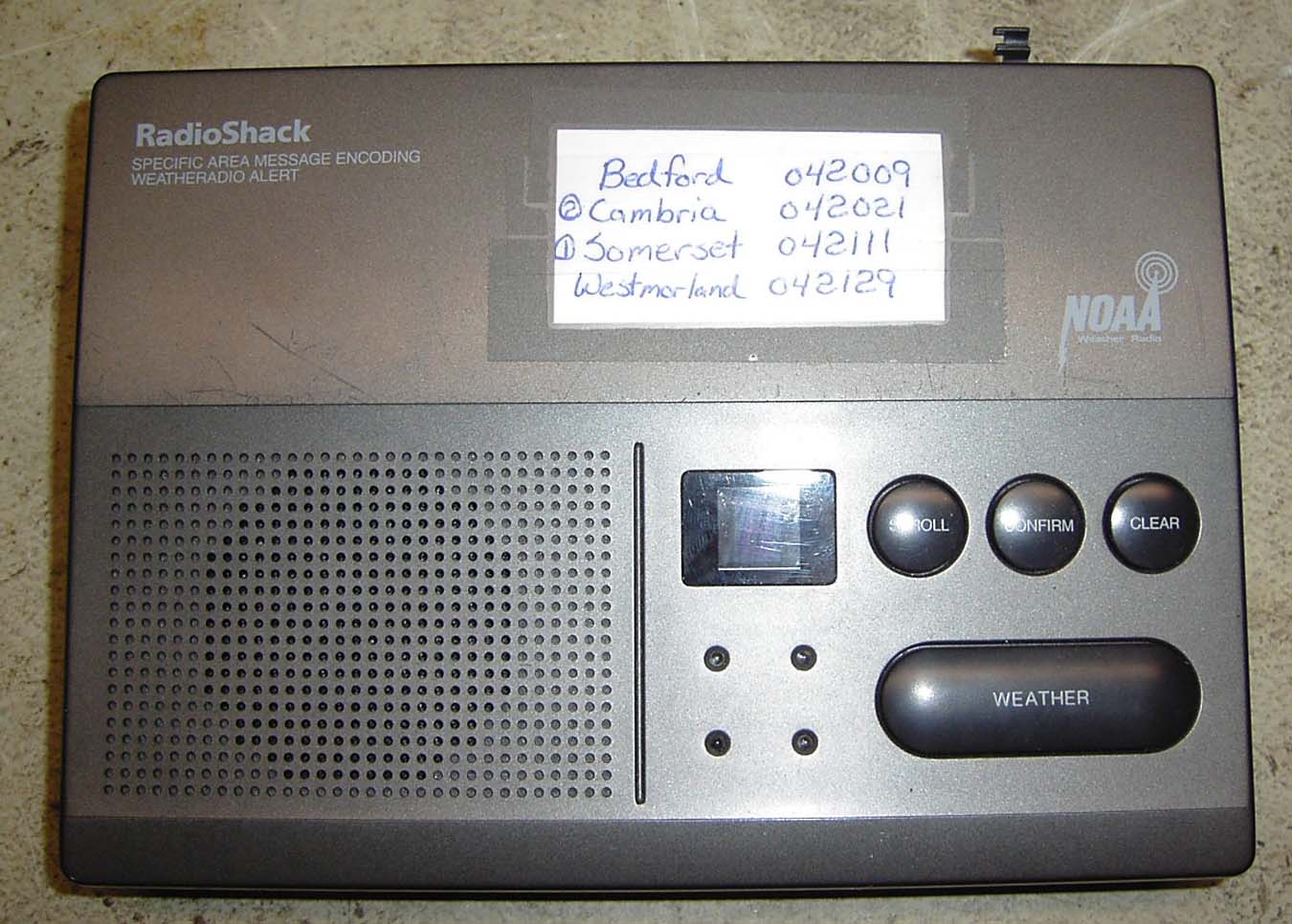
Except for the missing rod antenna and the "cheat sheet" of local codes this receiver
looks unmodified.
Amateur radio, public service, and severe weather training go hand-in-hand,
therefore re-transmission of severe weather alerts on amateur repeaters is a
desirable option. The Radio Shack 12-251 SAME technology weather radio is an
inexpensive way to add weather alerts to your existing repeater system. The
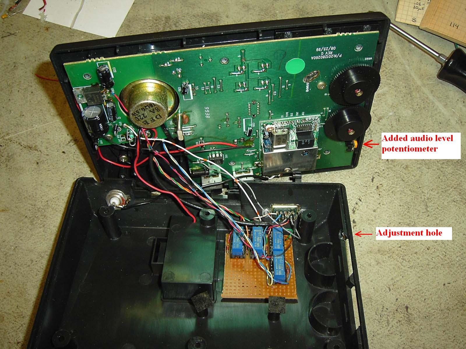
modifications described here involve adding a DE-9 connector and a BNC connector.
The DE-9 is to connect the receivers watch and warning indicators to the repeater
controller inputs, and to connect a repeater controller output to a relay whose
contacts are wired across the "reset" button of the receiver. The new BNC
connector is used to connect an external antenna to the receiver RF input. Buffer
relays are also added for greater isolation. The repeater controller pulses the
relays, and from the point of view of the weather receiver there's this virtual
finger that's pressing the buttons on the receiver. Internal power supply removal
is optional if you have a source of battery backed +12vDC available in your repeater
system. On this unit the watch, warning, and statement indicators remain lit while
the advisory is in effect. The outputs can therefore be used to trigger tail
messages based on the situation. Further enhancements may include recording the
alert messages on a DVR (either part of the repeater controller or hooked to it)
so they can be played back in an on-demand fashion for those that hear the alerting
tail message, but did not hear the original alert message. Repeater controller
programming is specific to the type of controller and the fuctionality desired
and is not covered in this article.
Modification Procedure:
You can click on any photo for a larger image.
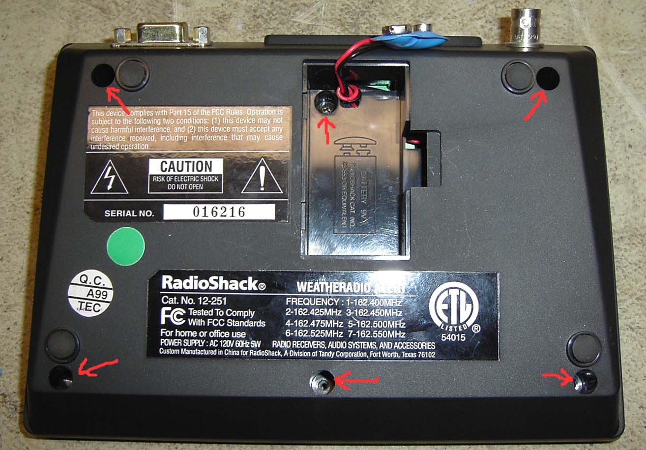
- Remove the 6 screws holding the bottom cover on the radio. One screw is located
inside the backup battery compartment as shown below.
- This step is optional. Remove the power transformer and power cord. Unsolder
the wires from the transformer's secondary winding from the circuit board. If
the power supply is removed, the radio will have to be powered externally by a +12vDC
source through the added DE-9 connector. This allows the receiver to be powered
by the repeater DC system.
- Unsolder the coax at the base of the factory antenna and remove the antenna. Leave
the coax connected to the circuit board.

- Drill and mount a BNC Chassis mount connector in the approximate position
shown in the photo above. Solder the loose coax end to the connector.
- Mount a DE-9 connector in the spot shown. Alternatively you could use the hole
that the rod antenna used for an exit hole for a DE-9 pigtail cable.
- Connect wires to the following places on the circuit board:
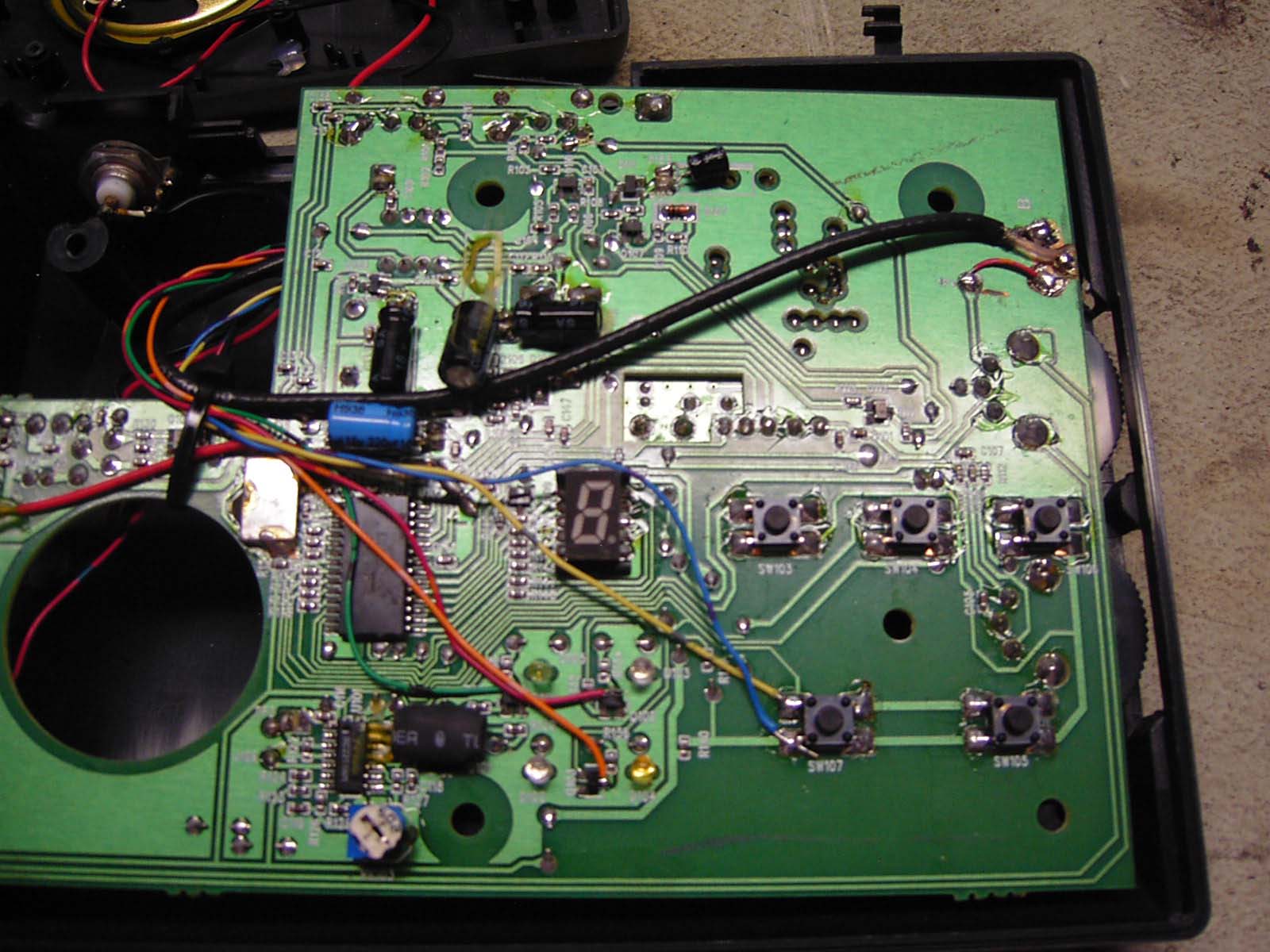
- Solder Side of circuit board: (as shown in photo below):
- Both Sides of SW107 (Weather Bar switch) Note that there are two switches
(SW105 and Sw107) in parallel.
- Q102 where R134 connects (Warning Indicator)
- Q103 where R136 connects (Watch Indicator)
- Q104 where R138 connects (Statement Indicator)
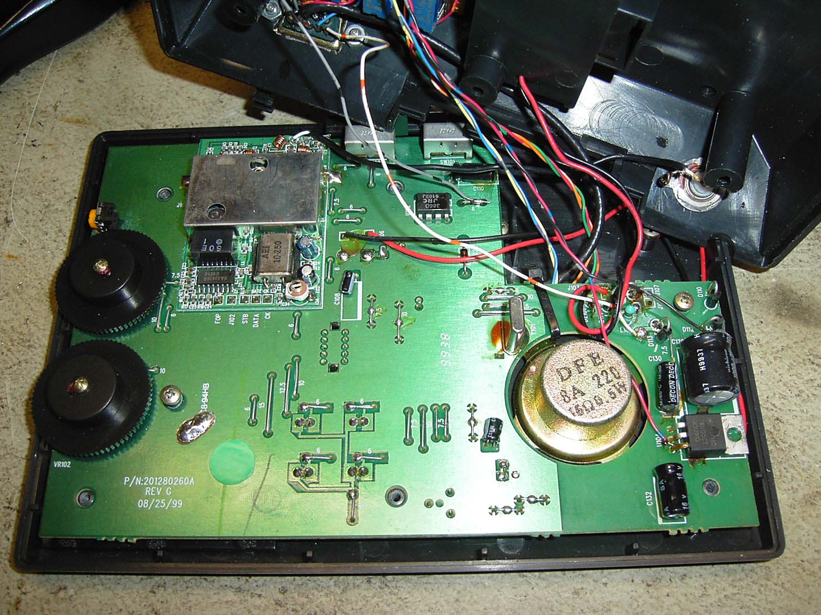
- Component Side of circuit board (as shown in photo below):
- Jumper marked "6" near C110 and U102 (This is the COS Output which will
be fed to the repeater controller link receiver COS input)
- Pin 3 of U104 - Right-most contact (+5v output to relay board)
- Anode of D113 (+12v Input for those that remove the power supply section
of the weather receiver)
- Negative Lead of C129 (Ground connection)
- Select only one of this step or the next:
Add a repeat audio level adjustment pot to the circuit board. Alternatively you could
mount yours on the back of the case next to the DE-9 connector.
- Looking at the photo below, drill 3 small holes in the circuit board near the
radio's volume control pot for a 20K or so stand-up right-angle-type timmer pot.
- On the solder side of the circuit board, use a dremel tool or similar to cut
rings around the pins of the pot for the wiper and the 'hot" leads to isolate them from
the ground plane.
- Connect the point marked "TP4" to the 'Hot' end of the pot.
- Run a shielded (optional) audio cable from the center wiper of the pot to the
DE-9 connector pin 3 (ground) and pin 4 (hot)
- If you chose to run full-level audio out just run a connection from "TP4" to the DE-9
connector pin 3 (ground) and pin 4 (hot). This will require the equipment fed by the modified
weather receiver (i.e. the repeater controller) to have an input level control.
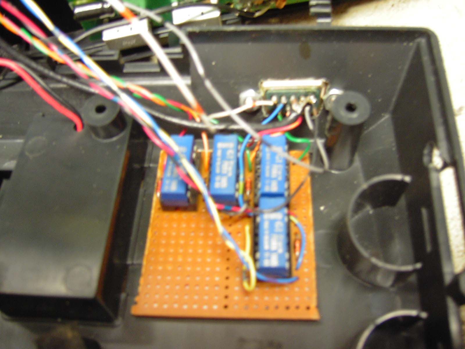
- Build the relay interface board shown below. All relays are 5vDC SPST reed type. Note
that there is enough extra room on the relay board to put the audio level pot there if you
wanted to.

Mount as shown below
- Connect the wires soldered above to the DE-9 connector as follows:
| Pin |
Function |
| 1 |
Plus 12vDC Input - this is for those that removed the power supply section of the
receiver. Apply fused +12vDC here. |
| 2 |
Touch Bar active input (relay coil to ground). Connect to a digital logic output
from your repeater controller (active low). |
| 3 |
De-emphasized Audio Output (active at all times). Connect to the link receiver
audio input of your repeater controller. |
| 4 |
Audio Shield / Ground |
| 5 |
Power Ground |
| 6 |
Statement output (n.o. relay contact to ground). Connect to an alarm input of
your repeater controller (active low). |
| 7 |
Watch output (n.o. relay contact to ground). Connect to an alarm input of your
repeater controller (active low). |
| 8 |
Warning output (n.o. relay contact to ground). Connect to an alarm input of your
repeater controller (active low). |
| 9 |
COS output. Connect to the link receiver COS input of your repeater controller
(active low). |
|
This modification was designed, built and documented by M. Scott Zimmerman N3XCC Jan 2005
Back to the top of the page
Up one level
Back to Home
This page originally posted on 13-Feb-2005
Photos and article text © Copyright 2-13-2005 by M. Scott Zimmerman N3XCC
HTML'd and edited by Mike Morris WA6ILQ
This web page, this web site, the information presented in and on its pages and
in these modifications and conversions is © Copyrighted 1995 and (date of
last update) by Kevin Custer W3KKC and multiple originating authors. All Rights
Reserved, including that of paper and web publication elsewhere.