Back to Home
Researched, Written, HTML'd and Maintained by Mike Morris WA6ILQ
|
Back to Tech Index Back to Home |
A Brief Overview of AC Power: Color Codes, And How To Avoid Killing Yourself and Others Researched, Written, HTML'd and Maintained by Mike Morris WA6ILQ |
|
CONTRIBUTIONS TO THIS PAGE ARE WELCOME!
Actually to any page at this web site! (even one that just points out a typo).
Notes:
|
I live in the southern California area, and a while back I made several business trips to do software upgrades at customer sites – thirty sites in six states in about twenty-five days. Most were in the five western states so it wasn't as bad as it could have been… I scheduled one weeklong trip across a 4-day weekend and used the days off to help out a group of teenage hams that were setting up a new amateur radio repeater site. They had built an 8 foot by 8 foot (2.5m by 2.5m) concrete block building and installed an adjacent 30 foot (9m) tower – a completely new site on some hilltop private property that initially had a UHF autopatch repeater and later on the tower grew to 60 feet and supported the same UHF repeater and also a remote base radio (an Icom IC-706 that covered HF, 6 meters and 2 meters). The slab was poured and the building was built from the ground up, using volunteer labor (the kids jokingly called it "slave labor"). Construction supervision was by one of the kids uncles, he was a retired mason (bricklayer) who also knew how to pour concrete and he insisted that all permits and inspections be done properly. They had trenched to the nearest power panel and laid a 2 inch diameter conduit for 240 volt AC mains power, an additional 1 inch conduit for telephone (autopatch) and ethernet wiring, plus a extra 3/4 inch conduit for future use or in case they forgot something. I was drafted by one of the local hams I know for my knowledge of repeaters, but I ended up probably saving someone's life when I took over supervising the AC power wiring installation, and in the process teaching a few young hams and their folks how not to commit suicide by electricity. I received a phone call a few weeks later from the mason thanking me and saying that the electrical inspection had passed "with flying colors".
In the electronics world, color codes rule – everyone knows the resistor color code (the cleanest version I've heard is "Big boys race our young girls but Violet generally wins gold or silver"), and back in the vacuum tube era there were standard color codes for transformer windings and even for molded capacitors (see the Allied Electronics Data Handbooks on the Tech-Index page at this web site).
Well, integrated circuits and transistors have replaced tubes as the predominant technology, and the "red is always +12 volts DC and black is always ground" mentality has (unfortunately) taken over.
Well, it's not that way in the electrical power world, where the black wire will kill you. This fact was brought home to me in a painful way in 1970 when I discovered two adjacent metal workbenches in a college school electronics lab were 120 volts AC hot to each other, and again later on when I was working at NASA / Jet Propulsion Laboratory in Pasadena California… JPL handles all of the unmanned space missions, NASA / Houston handles all of the manned ones.
USA AC POWER WIRING FACTS:
Note that there is no such thing anymore as "110 volt" or "220 volt" service anymore, although those numbers are still commonly used. In 1967 the USA changed its power grid from 110 volts or 115 volts or 117 volts or 120 volts (local power company choice) to a standard 120 volts / 240 volts. The official allowed tolerance is ±10%, so the official acceptable range is 108 volts to 132 volts or 216 volts to 264 volts for 240 volts. However I have found 120 / 208 volts (from two phases of a three-phase distribution system) in light commercial, some apartment complexes, and some condominium buildings. This means that many standard 240 volt appliances (like electric stoves, clothes dryers, etc.) are going to be underperforming when run on 208 volts. You will find that some manufacturers include a 208 / 240 wiring option (with 240 as the default), others can be ordered specifically for 208 volts, others are available for only 240 volts.
Back in the 1990s I replaced an open heater element in a friend's electric clothes dryer – and he chose to replace it with a 208 volt element as that was the power he had in the townhouse building. The 208v element was an available standard part (but a special order) from the distributor's warehouse. Later I found that an aftermarket manufacturer made a "universal" element with three connections… neutral, 208v and 240v and it was available at half of the distributors price! A few years earlier I helped replace a stove burner in a different friend's cooktop. They were available only in one part number which was labeled as 240 volts.
In case you are curious, the international standard green-yellow marking of the bonding ground conductors was introduced to reduce the risk of confusion by colorblind installers. Between 7% and 10% of men cannot clearly distinguish between red and green, which is a particular concern in older schemes were red marks a live conductor and green marks safety ground. If I have a choice between green / yellow and solid green, I pick the green / yellow.Whatever form it takes the "green wire" / protective earth conductor can never ever be interrupted by any type of switching, be it a circuit breaker, a switch, a fuse or anything else. This "green wire" is intended to permanently "bond" all of the normally unenergized parts of the equipment / appliance / fixtures to the safety ground bus back at the power service entrance. Under normal circumstances there is no current in the green wire – in other words this wire is strictly for handling fault current, and never, ever carries load current.
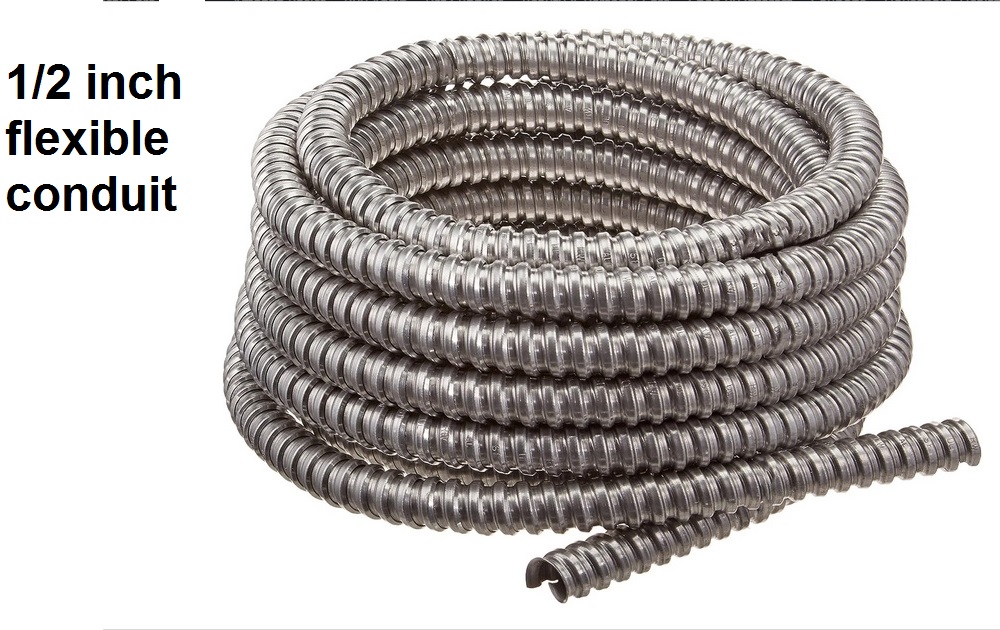
This article was proofread by two friends before posting… one is a retired electrician with 20+ years of experience in both residential and commercial environments, the other is a retired county building inspector (25+ years).Personally, I don't trust the conduit / flexible conduit to be the bonding ground – in addition to making sure that the conduit / flex is grounded (it's too easy for a clamp to come loose), I always pull a green wire along with whatever is going inside the conduit and treat the conduit / flex only as a construct for the physical protection of the enclosed wiring. Several times that required me to go to the next larger diameter flex. In fact, I've been called anal when folks see me use nothing but EMT (solid metal tubular conduit) or flex, metal outlet boxes, and lots of green pigtails to ground every outlet box, metal pull box and metal switch box (in addition to the outlet or switch itself) to the green wire. My usual response is: "I am doing this job as if MY mother or daughter will be living here". And I have NEVER had a problem with the local building inspector(s) (except for the fact that he thinks I overdo things).
A comment from the inspector:
"In older wiring systems (where 'old' is defined as the mid-nineteen-seventies and before), the conduit or flex may be ASSumed to be the bonding system. Some of the time, this is an un-founded ASSumption".
One personal pet peeve: Over the years I've seen several situations where a residential bathroom light fixture body is hot to the water faucet or to the sink drainpipe because:Another comment from my retired building inspector friend:
(a) the light fixture body and mounting box wasn't grounded…
(b) the switch was in the neutral lead and…
(c) the hot wire insulation inside the box had deteriorated and the copper wire was touching the fixture.
(d) the household plumbing (hot and cold) is metallic all of the way to the point where it is connected to the power panel earth grounding.
(e) the drain line plumbing is metallic all of the way to the point where it is buried in the earth.
In the 40+ years since the mandatory electrical overview class by a NASA / JPL electrician and a NASA / JPL safety supervisor (discussed later) I've not purchased or installed a non-polarized 2-wire plug (even if I have to disassemble a device and identify which conductor on the AC cord is hot and which is neutral). In fact, I've cut several non-polarized plugs off the ends of various cords (like on table lamps and kitchen appliances) and installed polarized ones. Replacement polarized plugs are widely available, even at ACE Hardware and Home Depot.Polarized 2-prong plugs have a wide prong (neutral) and a normal prong (hot). They are required on lamps that use a threaded bulb. The threaded sleeve of the light bulb socket must be connected to the wide blade (neutral).
My electrician friend told me a story that he had read in an electrical trade magazine many years ago: a child (in bare feet) was electrocuted when he contacted a metal portion of an older illuminated business sign. The sign was at the child's shoulder level and mounted on a wooden fence and surrounded by a flower bed. As part of the coroner's investigation the sign was dismantled to see what had happened. It turned out that:In short, the green wire has one very important purpose – to trip the breaker or blow the fuse by being a low resistance fault current pathway BEFORE a person touching a charged surface becomes the low-resistance path to ground.
a) sprinkler water and rain water had migrated inside the sign (which was over 20 years old),
b) the sign was constructed and mounted in such a way that water pooled in the bottom (plus the fence had settled, more at one end than the other),
c) the green wire was fastened to the bottom sheet metal of the sign with a single common sheet metal screw,
d) the submerged end of the green wire had corroded to the point it had broken,
e) a hot wire had been routed inside the top of the sign and the insulation became brittle due to a combination of age and the rising heat from the light bulbs,
f) the overheated baked / brittle insulation had flaked off the wire in chunks and many loose pieces were found in the bottom of the sign,
g) the now exposed hot lead had come into contact with the metal housing of the sign.
None of the above had been noticed since the sign still worked, but the combination resulted in 120 volts AC on the shell of the sign. A child in bare feet standing in a damp flowerbed coming in contact with the energized housing resulted in a fatality.
The article suggested extending the green wire to a position that is on the side or top of the housing to prevent pooled water from causing a disconnected green wire. It also suggested bonding together all sections of a multi-section metal housing sign with green wire jumpers. Lastly, a screened drain hole at a low point was recommended (screening to prevent flying insects from making a home inside the fixture).
I had a personal introduction to phase tape: From 1964 to 2007 I lived in a house that was built in 1939. Notes that were left in an envelope inside the house electrical panel indicated that the house was completely rewired somewhere between mid-1958 and late 1959. The feed from the power pole terminated at a breaker panel on the side of the garage. That panel had the meter, the main disconnect breaker, and 4 breakers just for the garage and workshop circuits. That panel also fed a 2 inch underground conduit (to the house) containing three large black feeders for the power to the house. One of the black wires had no tape (not a good idea). The second had several turns of red tape around each end. The third had several turns of white that had faded to grey. There was no green – in the era the house was built the code allowed the conduit to be the safety ground. In the house every bedroom ceiling light switch had a black wire coming into it, and a black wire with yellow tape going out of it. The kitchen and dining room were remodeled between 1962 and 1964 and the switched outlets and ceiling lights in those two rooms had no identifying tape – interesting, no? The two bathrooms were rewired around 1982-1983 (under my supervision) as part of a remodel and they had proper colored wire to start with.While we are mentioning tape, don't use the cheap chinese bargain-bin no-name black stuff on any AC power wiring that you are responsible for (or anywhere else, for that matter). It loses its "stickiness" with age and unravels, or it melts and turns into a gooey mess. I speak from experience. Use the real Scotch "Super 33" or "Scotch 33+" tape. Scotch "Super 88" is even better as it's thicker, has a better adhesive, and it has better IR / UV resistance (which is significant only if it's outdoors). The price difference between the cheap stuff and the Scotch 33+ / Super 33 is not worth having a splice "unwind" itself and possibly cause a short or worse, an electrical fire. Have a local union electrician show you how to tape up a wirenut. There is a non-obvious trick involving stretching the tape in the middle and not stretching the tape at the ends that you need to know in order to have your work pass inspection. While you are talking to him, have him show you how to mark a wire with phase tape. He will probably use more tape that you think is necessary, but he knows what the local building inspector(s) or AHJ want to see, and a few inches more tape on each phase marker, on each wirenut and / or splice is cheap compared to being forced to go back and redo the entire job.
I also found a ingeresting use of phase tape in a house that a friend purchased: the previous owner had replaced a ceiling light with a light / fan combination. Whoever did the installation replaced the single switch with a double switch, and then used the green wire (with blue phase tape on both ends!) for the fan... not the way I would have done it, and it definitely would not have passed an inspection by an AHJ.
Personal Opinion: the minimum electrical wire sizes specified in the NEC for amperage are inadequate on long runs as a wire size guideline for proper operation of equipment. The NEC considers the purpose of the circuit breaking mechanism (a breaker or a fuse) to be protecting the wiring (to prevent fires), not to protect the load from damage (including undervoltage). In other words, they don't care about proper performance of the load (your equipment) with minimal voltage drop, just the safety and integrity of the power panel, wiring and receptacle feeding your load. Unfortunately too many architects, builders and remodeling project managers allow the construction electricians to bid a job only based on local code requirements. And the electricians that do the work don't care because (a) the smaller diameter wire is easier to run, (b) the smaller diameter wire costs them less (i.e. lower material costs raise their profits), (c) they get paid the same hourly rate for running thin wire as thick wire, and (d) they won't have to live there, nor will they have to do the future maintenance (they are the construction electricians, not the repair or maintenance electricians).
Yet another Personal Opinion: The organization behind the NEC does excellent work, but the NEC's reliance on the green wire to trip a circuit breaker is too focused on just one method. If you want to protect against hot-wire shorts or leakage to ground, then use the device that's specifically designed to detect them and open the circuit – the ground fault circuit interrupter! (abbreviated GFCI, frequently shortened to GFI, also called a Residual Current Device (RCD) in europe) If a GFI breaker had been used on that MGM Grand circuit, it would have immediately tripped. The GFI compares the current in the hot wire and the neutral wire and if it's is different it opens the circuit, even without a green wire present. But having a green wire AND a GFI is better. Since that incident there are also Arc Fault Circuit Interrupters (AFCIs) (commonly called arc fault breakers) and explaining the difference between GFCI and AFCI is beyond this document, but look here. (Off-site pointer, opens in a new browser tab)
And there are also Dual Function Circuit Interrupter (DFCI) receptacles and breakers that combine both Ground Fault and Arc Fault (GFCI & AFCI) protection in one unit. (also an off-site pointer, opens in a new browser tab)
Note that as I write this AFCIs and DFCIs are new and according to a number of magazine articles the early units are prone to false tripping to the point that brand new houses are being sold and within a few months all of the code-required AFCIs are being replaced with standard breakers.
Let's jump back to Low Voltage issues…
The older Radio Amateur's Handbook published by the ARRL (older being defined here as late 60s / mid 70s) had a VERY nice one-page American Wire Gauge (AWG) table in them that included a column that listed the current carrying ability of the wire and another column listed the resistance of the wire per one hundred feet. It's worth hunting down a copy and xeroxing that page for your personal file cabinet. Later issues had the same table but somewhat reformatted. You will discover that doubling the current rating is NOT just one step up the AWG table. And remember, a wiring resistance of 10 ohms per 100 feet and two amps of load current is equal to a forty volt drop at the load 100 feet away – twenty volts outbound, and another twenty volts on the return. This means that your 200 watt soldering iron is running on 80 volts instead of 120 volts and just might not get hot enough to solder that connection at the top of your tower.
And that's just a 200 watt load – how about that RV or 5th wheel trailer that has one, two, or even three 1200 watt (or larger) air conditioners in it? And don't get me started on the stupidity of running solid wire in an RV… also known as a rolling, vibrating continuous earthquake and windstorm. If stranded wire is legal for 120 volt and 240 volt AC circuits in passenger carrying boats then why isn't it legal in privately owned RVs? Using any solid conductor wiring in a moving and vibrating vehicle (RVs, boats, etc) can lead to stress fractures in the solid conductors, especially if the wiring is not fully and firmly anchored down. Every marine supplier sells stranded wire for the 120 volt and 240 volt circuits in a boat, why not in an RV? Stranded Romex also exists, it is pricier, but does last much longer than solid wire in any application which has vibration or requires movement and / or flexibility. It's available in both 2-conductor and 2-conductor with ground, possibly in higher conductor counts.
Low voltage causes even more problems on electric motors – you can actually kill an AC motor with low voltage / too much voltage drop. Using conductors that are just two AWG sizes larger can cut that voltage drop by 50% or even 75%. (This is why the kids mentioned in the story at the top of this page used a two-inch conduit from their new building to the nearest panel – they ran a ground, a neutral, and two hot wires. And all were "fat" wires (deliberately oversize in the conductor diameter).
The NEC specifies that residential electrical must be a 14 gauge wire or larger (remember that smaller AWG numbers indicate a larger wire size) for use on a 15 amp circuit, but only up to about 50 feet of wire length (and outlets are completely forbidden on 14 gage circuits). The NEC specifies 12 gauge for a residential 20 amp circuit, but only up to about 50 feet. For a 30 amp circuit the NEC wants you to use 10 gauge – but again, only up to about 50 feet.
The NEC handles commercial buildings differently from residential – for example, in commercial environments the smallest wire size allowable is 12 gauge.
Regular circuit breakers are designed to trip on either overcurrent or thermal events (GFCI and AFCI breakers have additional trip mechanisms). The current detector is a coil – i.e. magnetic. Common breakers have a short time magnetic trip and a longer period overcurrent thermal trip. Every breaker design has a trip curve that shows exactly when they will trip based on the current. Also the ambient temperature of the breaker will affect its trip point. Remember that common breakers are rated for peak load at 100% of nameplate rating. The sustained load test specification is 80% of that, so a 15 amp breaker must trip at sustained loads of 12 amps, a 30 amp breaker must trip at sustained loads of 24 amps and a 50 amp breaker must trip at sustained loads at or above 40 amps. So for a 15 amp breaker the limit is 80% of 15 amps which is 12 amps (which is why the vacuum cleaner "amp" wars from the 1970’s to the 1990’s stopped at 12 amps of "cleaning power").
You can verify the trip point with a clamp-on ammeter – you'll be able to tell pretty quickly if the current draw is exceeding the breaker rating. Note that clamp-on ammeters come in two versions: AC only and the version that responds to both AC and DC. An electrican that wires your house can do his job with the AC-only version, if you are going to purchase one and will ever need to read DC current then I'd suggest spending the extra money and getting one of the AC / DC variety.
Any time you remove a breaker from a panel you will want to take a close look at both the buss bar in the back of the panel and the mating clips on the back of the breaker for any signs of overheating (a discoloration in the metal or a weakness in the contacts). Good breaker panels have copper buss bars. Cheap panels have aluminum buss bars that corrode (especially in coastal or other high humidity areas). Most of the less expensive panels are made to a price and have aluminum buss assemblies. If the connection is bad at the buss bar it will discolor and any sparking may leave pits in the bar. If possible clean the bar carefully with emery cloth and coat it with an aluminum corrosion inhibitor like Penatrox before snapping in the new breaker. If the discoloration, pitting or corrosion of an aluminum bar is excessive then REPLACE it with a copper bar. And if you have to replace one breaker bar in the panel then replace both.
If you are involved in any new construction or remodels that require replacing breaker panels please specify a that the new breaker panels must have copper internals – NO ALUMINUM parts.
Another point: always check the amperage of the main breaker versus the panel.
I once found a residential breaker panel with a "100 amp" sticker on the nameplate inside of the panel… but the panel had a 250 amp main breaker between the meter and the buss bars that connect to the breakers. That panel had a 50 amp breaker pair (i.e. 240 volts) labeled "air conditioner", a second 50 amp pair labeled "oven/microwave", a 50 amp pair labeled "stove", a 30 amp pair labeled "dryer" and a assortment of 15 amp and 20 amp breakers for the bedrooms and other rooms. Do you see a potential problem there? I was surprised that the breakers were even labeled. I showed this to the homeowner, she commented that was how the house came to her. Obviously the pre-purchase inspection hadn't caught it, or the inspector was the sales agent's relative. Within a month the entire panel had been replaced – with a brand new 250 amp panel. And that new breaker panel had copper internals.
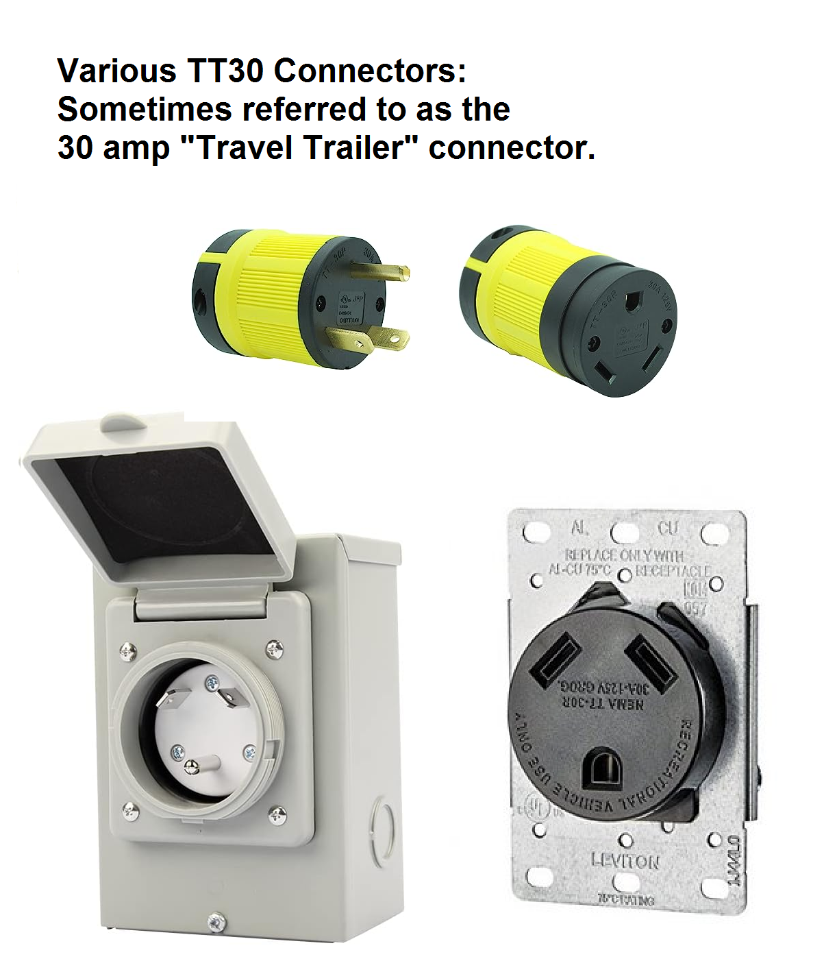
Another 80%-of-peak-load issue is found on a large number of older RVs / motor homes that use a "TT30" connector. The connector was dubbed the "travel trailer" connector but was adopted by the entire RV industry as the standard AC power connector for decades. The TT30 is rated at 30 amps. What many people don't realize is that both the TT30 plug and the outlet are rated for 30 amps but only for up to 3 hours. If the load continues for over 3 hours it should be limited to 80% or 24 amps per the NEC. As I said above, the NEC is designed to protect the power supplying system, not the connectors or the load! It is not uncommon for the common TT30 connector prongs (actually, any connector) to corrode and develop contact resistance resulting in an overheat condition. I've seen the TT30 plastic around a pin soften and / or melt from the heat caused by a corroded pin and never blow a fuse or trip a breaker. And it's not just corrosion that can generate the overheat situation, I've seen a loose connection on one of the screws in the plug do it and melt the plastic housing of the connector (and again, not trip a breaker). Another problem with the TT30 is that the pins are sized for AWG 10 solid or stranded wires. If you want to reduce the voltage drop with an AWG 8 or 6 cable you are out of luck – it won't fit. Nobody offers an aftermarket TT30 connector that allows for larger wire sizes.
The RV industry outgrew the TT30 connector and replaced it with the NEMA 14-50, a 4 conductor connector that was already in wide use for commercial / inductrial use and for residential electric stoves. In the RV industry it's commonly called the "50 amp" connector (one reason was that with only 3 conductors the TT30 does not support 240 volt appliances like large air conditioners). I've seen writeups on RV web sites that point out that the "50 amp" name is incorrect as the four pins of the connector actually support two independent 50 amp circuits so it can theoretically handle 100 amps of load. However from the viewpoint of NEMA and the NEC it is correct because each conductor can carry a max of 50 amps. The NEMA 14-50 connector doesn't solve all problems,(especially environmental) as the copper pins can still corrode, overheat the connector and melt the plastic.
Another issue: Aluminum wiring was introduced to homes in the USA in the mid-1960s. At that time the price of copper was very high, and aluminum was a cost-effective alternative. Many homes were wired with aluminum wire through the mid 1970s. Aluminum wire requires outlets, switches and breakers designed for (and labeled as rated for) aluminum wire. Fires start at connections and terminations, because that's where the oxidation occurs, which causes loose connections with high resistance and overheating. Aluminum wire connections can overheat enough to start a fire without ever drawing enough current to trip a circuit breaker or blow a fuse. If you ever work on an aluminum wired location make sure the breakers, switches, outlets and wire nuts are stamped "CO/ALR" (for "COpper-ALuminum-Revised"). The early devices marked "AL-CU" or "CU-AL" are no longer approved and when replacement is needed must be replaced with the later CO/ALR units. One note – aluminum is not as good a conductor as copper and code required a two-gauge-bump, a circuit that would normally be wired with 12 gauge copper required 8 gauge aluminum. Many installers cheated and bumped it only one step. Some didn't bump it at all. The NEC no longer allows aluminum wire, when found the aluminum must be replaced with copper. This can be a nasty surprise when a house is put up for sale and the pre-sale inspection drops the aluminum bombshell… In some areas the house has to be completely rewired before the title can be transferred, and in other areas it has to be rewired before it can even be listed for sale.
If you have any questions about what wire sizes or what types of insulation are legal for your conditions and building environment you need to check with the local AHJ (Authority Having Jurisdiction, normally the local building code inspector) before you get started. It's way cheaper to ask first rather than to be forced to rip everything out and start over. And don't trust the sales guy at Home Depot to know the local codes (he may have been selling carpet, lumber or grass seed the week before). If the locals have different rules than the NEC, they are usually tougher and they are the ones that you have to follow to get the local inspector to sign off on the work… (as long as you use the proper size and type of wire – i.e. copper, THHN insulation, or whatever they want to see – you will never have a problem if you go lower in AWG / larger in wire size (conductor diameter), or better (in the type of insulation).
The actual NEC is big (over 900 pages), expensive and pretty dry reading, but overview books are available at most good bookstores and at web-based booksellers like Amazon. And there are the specialty technical-only booksellers.
A more accessible source of information is the overview books written for do-it-yourselfers that are available at Amazon and other places. My favorite is "Ugly's Electrical Reference" by George Hart, it's about 200 pages and you can buy it at Home Depot. And don't forget your local public library – they sometimes have copies of the Ugly Reference or even a current or a relatively recent NEC in the reference section, and some bigger libraries have overview books and older issues of the NEC in the circulation section. And you occasionally find the $25 and $35 Home Depot overview books for a dollar or two at church rummage sales. Used bookstores are interesting places as well.
I am not an electrician, nor do I play one on TV or on this web page. But I do know how to read, and I have read sections of the NEC, and several other books. I've also been an assistant to a professional electrician on several remodels. As a result I've had the opportunity for long discussions with union journeyman electricians, and both city and county building inspectors. Personally, in the last 20 years I've never installed any branch circuit smaller than 12 gauge (even for a two-amp bathroom ceiling fan). Every bit of AC power wiring that I personally do uses wire sizes that are at least NEC commercial – and in many cases I go even further (at one friend's house I used 6 gauge wire (that's what is called for in a 70 amp circuit) for a 75-foot run to a 20-amp air conditioner since low voltage does nasty things to AC motors). To be specific, the air conditioner nameplate (3 ton, 1/6th HP, 208/230vAC motor) said "MIN. CKT AMPACITY 18.8" and "MAX FUSE OR CKT. BKR. (HACR PER NEC) 30".
Translation: The air conditioner can pull a max of 18.8 amps but you should use a 30 amp fuse or breaker. That 18.8 max amps makes #12 AWG legal to use. Sorry. If you say 30&nsb;amp fuse or breaker I'm going to use #10, since it can carry 30 amps (for up to 3 hours) and if I have any #8 or #6 around I'll use that first.
Most homes in the United States are wired with either THHN insulated wires in hard conduit or flex or with non-metallic sheathed (i.e. "NM") cable (often referred to by the trade name "Romex" – another proprietary product name that has become a generic). Romex is the least expensive for a given size and is appropriate for dry indoor applications. The designation NM XX‑Y indicates, respectively, the type of sheathing (in this case, Non-Metallic), the size of the conductors (in AWG), and the total number of circuit conductors not including the green safety grounding conductor. For example, NM 14‑2 cable contains three 14 gauge conductors, a black wire, a white wire and a bare wire (for the safety ground). NM 12‑3 cable contains four 12 gauge conductors, a black, a white and a red plus the bare wire ground. When NM XX‑2 cable is used on 240v circuits (like to a large window air conditioner), the one black, one white, and a bare grounding conductor conflicts with the NECs rule about the white conductor identifying the neutral conductor (a 240 volt 2-wire circuit does not have a neutral). The NEC allows the white wire to be used as the second hot conductor, but mandates the white be marked with phase tape on BOTH ends.
Update 2010:
Since this article was written a number of manufacturers have started color coding the outer sheath of their NM‑cables. The color indicates the gauge of the wire inside the sheath. The color coding started about 2001 and as of this update is still voluntary. If you have older wiring with color sheaths, don’t assume it complies with the current color coding. Check sheath labeling for wire gauge and wire count. Most manufacturers that do color the sheaths now follow this color code:
BLACK = 8-gauge or 6-gauge wire, 45- or 70-amp maximum circuits.
ORANGE = 10-gauge wire, 30-amp maximum circuit.
YELLOW = 12-gauge wire, 20-amp maximum circuit.
WHITE = 14-gauge wire, 15-amp maximum circuit.
GRAY = UF (underground feeder). Since all UF cable is gray, check the printing on the sheath labeling for gauge and conductor count.
UF is rated for direct-buried or run in conduit and is used primarily to bring power to detached garages, outbuildings or for outdoor
lighting.
It must be protected from physical damage by conduit where it is exposed (enters or exits the ground).
(end of 2010 update)
The electrical color codes are more extensive than anything I've listed above. See the web page at:
www.allaboutcircuits.com/textbook/reference/chpt-2/wiring-color-codes/ for an excellent overview.
Wikipedia has an excellent writeup that goes into a lot more detail than this article at: http://en.wikipedia.org/wiki/Electrical_wiring. It also includes a color code chart for other countries.
There's an article on three-phase power that includes color codes at http://en.wikipedia.org/wiki/Three-phase_electric_power.
The mathematics of three phase power is covered in a different article at http://en.wikipedia.org/wiki/Three-phase.
There is also some information on single phase power at http://en.wikipedia.org/wiki/Single_phase_electric_power.
At the new radio site mentioned above the project supervisor (the mason) listened when I pointed out my concerns about undersized wire and future high power loads in both sides of a duplex outlet so instead of using 14 gauge they used 10 gauge on every outlet. The kids wired every branch outlet with a 10 gauge black, a second 10 gauge (red, blue, brown or yellow) and a 10 gauge white (neutral), to each outlet box (plus the green/yellow safety ground, also 10 gauge), so that in the future 220vAC can be easily obtained at any location in the room if needed. A few folks thought that the 10 gauge was serious overkill for the load involved. The project supervisor (the mason) ignored them.
The two overhead lighting circuits were wired from two different breakers (one on each phase) with 12 gauge – a green/yellow, a white and two hot wires (red and blue). They mounted two light switches by the door, feeding a pair of four‑foot dual tube fluorescent fixtures. The two phases, two breakers, two switches and two fixtures on the lighting insured that there would be light even if one of the lighting switches or breakers failed, or if they lost a phase from the upstream breaker panel. Doing things that way is just good planning and design… I've seen too much new construction that has only one circuit per room. When I am asked to help wire a house I suggest extending three circuits to each room: the first powers the ceiling light (and that circuit might power the ceiling lights in several rooms), the second for the outlets on two adjacent walls (and possibly multiple rooms) and the third for the outlets on the other two adjacent walls (and possibly multiple rooms). No matter what breaker you have to switch off to repair something, if you need light you just turn on the ceiling light, or plug your work light into an outlet on the opposite wall (you won't need an extension cord that runs to the next room or to the far side of the house).
Tools that you might not think of: A 100 foot Greenlee (or similar) brand nylon fish tape is rather expensive, but worth it as it will last you for many, many years (like my dad used to say, "Buying quality tools only hurts once"). Add to your shopping list a squeeze bottle of Scotch #77 wire lube to help the wire slide through the conduit or flex and a black Sharpie marking pen (to label the circuits – just use the Sharpie to write on the inside of the outlet boxes as to where the wire is from, i.e. "FRM CB13" ("From circuit breaker #13"), on the inside of the ceiling light fixture you could write "FROM CB #4 VIA LEFT SWITCH BY DOOR". The next gentleman that has to work on your wiring will bless your thoughtfulness. Some people write the panel and breaker info on the back side of the outlet and switch plates, but plates can be replaced or swapped around when the house or a room gets repainted. I've seen industrial locations where the outlet plates were engraved (and paint filled) with the breaker panel number and the breaker number… the two outlets on my workbench at NASA-JPL were labeled "264/2LA-13" and "264/2LA-15"… (building 264, second floor, panel LA, breakers 13 and 15).
The school electronics lab workbenches I mentioned above? They were sitting on a linoleum tile floor, which was on top of a second, older, asbestos tile floor, each of which acted as an insulator. One bench had been added to the rear of the room a number of years after the lab was built, and placed in a back corner of the room to be used as an equipment repair bench (electronics students are rough on equipment…). The story was that the back bench AC outlets had never worked because they had never been hooked up; hence it was used as a storage bench and library table. I accidentally discovered its exterior was hot one day when I leaned on it and touched an adjacent bench. Thirty seconds (with a VOM) later I determined that the shell of the bench was 120vAC hot to either of the nearest two benches, and 5 minutes later I knew that it wasn't just high resistance leakage current – you could light a 120v 100 watt incandescent light bulb to full brilliance by connecting one side to the "dead" workbenches AC outlet ground screw and the other side to the adjacent benches ground screw. Upon dismantling the bench, we discovered that it was connected with the black wire to the metal framework (the bench "ground"), and green to the hot wire of the outlets, after all black is ground, right? The breaker feeding the "hot" bench was quickly located and switched off, and locked out until the wiring was corrected by and signed off by the school physical plant department. Yes, we could have swapped green and black ourselves, but to quote our instructor "Never get a union electrician angry at you – and especially when your paycheck is signed by the same person as signs his paycheck". Besides, I think he wanted the campus electricians to see the reversed wiring – it had been that way for at least the eight years that he had been teaching there (can you say "liability"? …).
About five or six years later I was working at NASA / JPL in Pasadena and was suddenly dropped into a similar situation. Our group was charged with the regular maintenance of all of the data processing equipment used in two adjacent buildings dedicated to the ongoing operation and support of spacecraft missions (buildings 230 and 264). In many situations JPL designed and built its own equipment. One multi-cabinet rack mounted system used 36 power supply shelves of four separate power supplies each (+12v, -12v, +5v and -5v DC). The tech that had wired them (probably a summer intern) had done so in the "electronics" fashion. He had treated the black wire of the AC power cord as "zero volts", the white as "hot", and the green as chassis ground. Both the AC fuse and the AC power switch of each power supply shelf were wired in the white lead, which left exposed terminals in the power supply hot to the chassis when the power was switched off – not a good thing when you have your hand inside the equipment to change one of the eight hard-to-get-at fuses (one for the AC side and a second for the DC side of each power supply), or to press a reset button on one of the circuit boards.
Note: There are two schools of thought on the sequence of switch and fuseholder. When I was there the in-house manufactured equipment I worked on was wired with the hot wire going first to the switch, then to the fuse holder, and then the load. The idea was that when the switch was off then everything inside the box – even the fuse holder – was dead. The other school of thought says that the fuse is first so that if it blows everything is dead, plus you can remove the fuse and put in your pocket and that prevents the equipment from being turned back on when you aren't looking.I'm not aware of any NEC section that mentions the sequence of switch and fuseholder inside any device (applicance, consumer electronics, commercial / industrial equipment, etc).
Unfortunately the equipment was installed in a set of six 6-foot-tall cabinet racks that were in a long row of twenty racks in the main computer room of the Space Flight Operations Facility (commonly called the SFOF, pronounced "ess-fof"). This was the main mission computing center for all of JPL, and was used to support multiple simultaneous spacecraft missions. The biggest problem was that the SFOF had several missions in progress, the most visible of which at that time was Viking… and on a absolutely unchangeable deadline: Viking One was over half way to Mars, Viking Two was 18 days behind, and simple physics tells you that neither were going to wait for the folks back home to get their equipment rewired! Remember folks, physics makes the universe go 'round. Fortunately the wiring error was discovered (by one of my co-workers) before someone was hurt, and after several discussions between us, our group manager, the system designer, the SFOF electricians, their supervisor and the Lab safety supervisor it was decided to simply cut the 36 AC power plugs off the equipment power cords (this was in the days of wired-in power cords with molded-on plugs) and to mount 36 brand new plugs with the black and white wires deliberately reversed on the screws of the plugs. Established electrical safety protocol(s) of the time required a 3 inch by 5 inch red cardboard trouble tag to be taped to the front and rear outer doors of each cabinet rack, 36 more were used, one on the front of each power supply tray, and 36 more were used, one zip-tied to the plug end of each of the 36 power cords. Yes, a lot of overkill, but when two facility electricians, the electricians supervisor, the lab electrical safety specialist, his supervisor, his department manager, the equipment designer, his supervisor and the local federal OSHA representative are breathing down the back of your bosses neck pointing out his workers lives are involved, the cardboard tags are cheap (and gets the AHJ off of your back). Each of the 144 tags identically described the same identical deliberate wiring error in the plug, the same identical reason for it, provided the same three contact names and phone numbers, and listed the same will-be-repaired-before date… we should have had the JPL print shop make 144 of them or used a rubber stamp kit… (yes, this was the redundancy proliferation and reduction group in the department of redundancy department in the redundancy control section of the redundancy management division – typical NASA). Plus we were instructed to lock the rack cabinets until the problem was repaired – and locked equipment cabinets was something that was never, ever done in the SFOF equipment rooms. There was a reason that there were large CO2 extinguishers hung on wall brackets every 20 feet on every SFOF equipment room wall… So we cheated (a little)… we locked the cabinets but every tech and every lead tech was issued a key the next day… (all 26 of us). The supervising tech and the department manager were also offered one, but both declined.
At some point in the above discussions one of the federal OSHA representatives casually suggested that the JPL Safety folks have a staff electrician walk the electronic technicians (especially those in the design / construction and maintenance groups) through an AC Power Orientation class which up to that point didn't exist. A mix of "you're absolutely right", "good idea", some bobble-head-style head nodding and other similar affirmations were heard and seen. By the time the OSHA representative's casual suggestion filtered up the three or four management layers, across the bureaucratic morass, and back down again to our group it had turned into two (identical) formal training classes (complete with a 3-ring binder workbook), one in the morning for 1/2 of the day shift plus the entire night shift, and a second one in the late afternoon for the other 1/2 of the day shift plus the entire evening shift. Attendance at one of them was mandatory which meant that the evening shift and night shift folks had a 12-hour day and got overtime pay (our group provided 24x7x366 support). Plus it would be videotaped for new employees, i.e. due to employee turnover – the newbie could watch the tape(s) and get the full benefit of the class (or so they say…) The first version of this article was written from those 1976 class notes… (To this day I'm still surprised that the video of the class wasn't made mandatory training lab-wide for anyone involved in electrical or electronic equipment maintenance or design).
Months later, after the two Viking landers were successfully down on Mars (touchdown of Viking 1 was on July 20, 1976 at 0512 Pacific Time, and I was in the SFOF watching the video monitors, along with what seemed like every lab employee whose badge gave them access to the building). Viking 2 landed on August 7th and after the background noise level around the SFOF had quieted back down to something approaching "normal", I scheduled progressive equipment outages with the appropriate folks and I budgeted one shift per day across three weeks to remove, rebuild and reinstall of the power supply shelves… with the black wire as hot, and the white wire as neutral and the green wire as chassis ground. As long as we were doing rebuild work on the system we also decided (with management approval) to zero out the maintenance technicians "wish list" for that system… Among other things we relocated all eight power supply fuses on the shelf to indicating fuseholders mounted in the front panel of that shelf, plus we added a guarded reset button to the front of the logic shelf… you had to lift a cover before you could press the button (it was in parallel with the one on the main logic card… we were tired of removing six screws on a cover panel and then twisting our hands into a contortionists form of the Vulcan Nerve Pinch to press the secret magic reset button, and then replacing the panel and the six screws). Another senior tech and I modified two power supply shelves at a time, six shelves per rack, for all six racks of equipment. Plus, as good hams always do, we added a few other improvements that we deemed necessary, then red-lined a new set of as-built drawings and submitted them back to Documentation Control. As we progressed down the line of cabinets we stripped the red trouble tags off the equipment and gladly tossed them in the trash (I should have kept one of them).
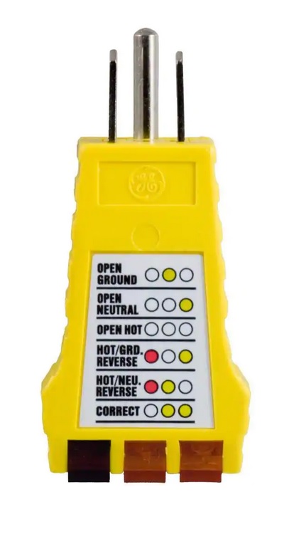
As a final note, improper AC wiring is far too common, especially in residential areas, and if you don't have to pull new cabling it is usually easy to fix. Recently a friend was transferred by his employer to an area near me. He and his wife had been shown a number of houses by various real estate agents, and together they trimmed the final list to five. My friend asked for my help in making the final selection – a fresh set of eyes, so to speak. As we walked through the five houses I took about 20-30 pictures per house plus written notes on the visible problems / defects / concerns in each house, and I also bent over and plugged an outlet wiring tester into every AC outlet that was easy to get to (the tester is a rubber plug with three indicating lamps under a clear cap – it is available from most electrical supply houses, Home Depot and even Ace and TruValue Hardware). Over 20% of the outlets in the five houses we looked at had either open grounds or reversed hot and neutral wires… this is not a good percentage! And in cases like this an open ground usually indicates that the selling homeowner has simply replaced the old 2-wire outlets with new 3-wire outlets to make the house look like it's been rewired…
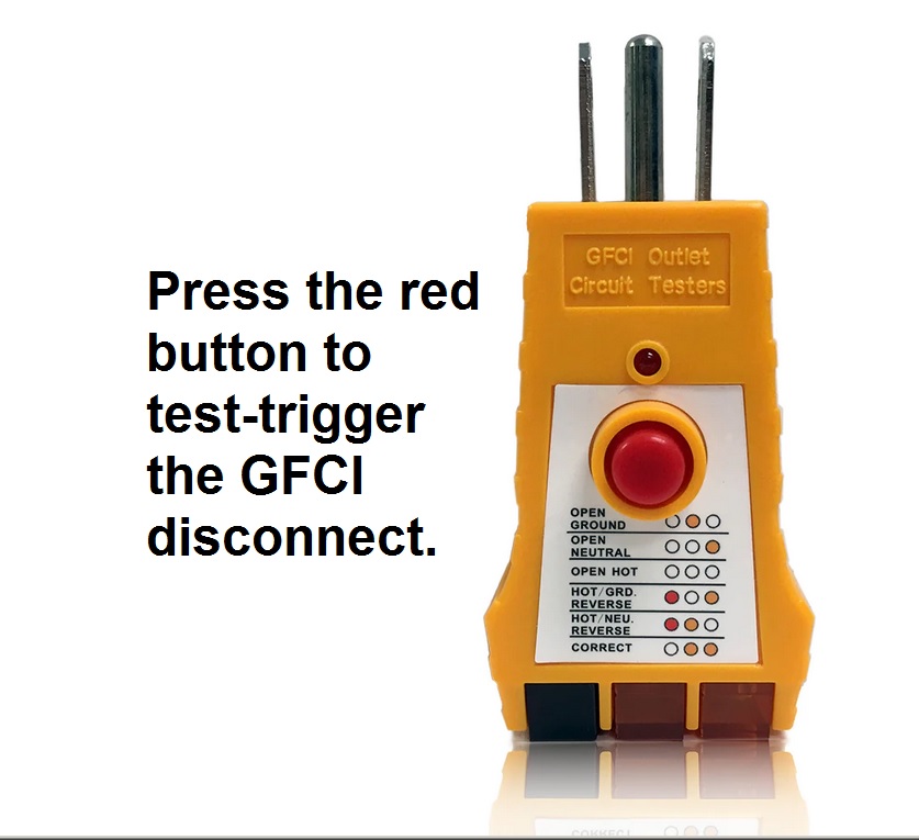
Click here for photos of an outlet tester and of an outlet and GFCI tester (sometimes called a GFI tester). If you are going to buy one new, get the GFI tester version. And note that the three indicators only need a few milliamps to light up – the tester can say that the outlet is good but it could be functionally dead (i.e. not delivering usable power due to a high resistance connection somewhere upstream).
Permission to any group to use this writeup is available for inclusion in any newsletter or bulletin for noncommercial, nonprofit, educational and public safety use within the scope of the U.S. Copyright Law. Just drop me an emailed note before you go to press.
Back to the top of this page
Back to Tech Index
Back to Home page
Contact Information:
The author, Michael Morris WA6ILQ, can be contacted here.
This page created and is copyright © Michael R. Morris WA6ILQ July 2003 and the date of the last revision.
This web page, this web site, the information presented in and on its pages and in these modifications and conversions is © Copyrighted 1995 and (date of last update) by Kevin Custer W3KKC and multiple originating authors. All Rights Reserved, including that of paper and web publication elsewhere.