Back to Home
Bonding and Grounding
Made Simple
By Dereck Campbell KF5LJW
|
Back to Tech Index Back to Home |
Amateur Radio Bonding and Grounding Made Simple By Dereck Campbell KF5LJW |
|
1. BACKGROUND:
No subject generates more debate than Bonding and Grounding. It starts with incorrect information, ignoring fundamentals, and a lack of using clearly defined terms. As electrical systems advanced over the last century, common return paths for power and signal circuits became "ground," whether connected to earth or not. "Ground" becomes vague, misinterpreted, ambiguous, and magical, defying the laws of physics.
In my 40-year Telecom, Utility, and Wireless industries, I had the privilege to work with the pioneers in power quality and lightning protection. I sat on NEC code-making-panel 9, contributed to IEEE standard 1100-2005 "Best Practices Power and Grounding Sensitive Electronic Equipment, authored Engineering and Installation standards for MCI-Worldcom, and Verizon Wireless. I am a student of all the performance grounding documents like Motorola R56, MIL-HDBK-419A, ANSI/TIA/EIA-607, and ARRL Bonding and Grounding for Amateur Radio. All documents specify Single Point Ground architecture. The only tangible difference between them is the acronyms and terms used. The methods presented here are the methods used by professionals adapted to ham radio usage.
This guide addresses the challenges facing ham radio operators. Your two most significant challenges are; using 12-volt automotive radios with 2-wire power and ground architecture inside your home's 3-wire architecture. The two systems are incompatible with each other. The 2nd issue is the ground loop created when you place radios in between two grounds. The reader only needs to understand the fundamentals of DC and AC power circuits, Ohms Series, and Parallel circuit laws; additionally, how frequency and impedance interact with inductors and capacitors.
2. MYTHS:
First, I must bust myths because they can prevent you from drawing the correct conclusions. Apply fundamentals to test a myth. If it cannot stand up, it is a myth. Top 5 myths:
1. Earth grounds are at 0-Volts - presumable respectively to each other. Drive two ground rods in dirt 20 feet apart. Those two rods will be at different voltage potentials. Earth is a resistor with current flowing, resulting in voltage potential between any two points along the surface. Apply Ohm's law: Current x Resistance = Voltage. You can measure the voltages with a DMM and Oscilloscope. Myth busted.
Where this can get you into trouble is placing your radio equipment between two earth ground electrodes. If you drive a rod outside the shack, another rod on the opposite side of the house where the AC Service enters will place you in a loop. You bond the two rods together with your radio equipment when you plug your DC Power Supply into the AC wall receptacle, creating the ground loop. The loop provides a path for both internal and external common-mode currents to flow through your Equipment Ground Plane or EGP. One of those external currents is lightning.
Fact: You use earth as your 0-Volt reference point. Keep in mind a 0-Volt reference point does not necessarily mean earth. It can be the chassis of a car, the hull of a ship, or a ham sandwich sitting on your dining room table if you want. It does not matter what voltage the reference point is. It is the singular reference point used to reference everything in a protected area. The ground electrode system can be 1 or 100 rods bonded together in the dirt with common-mode current flowing through it. We only connect at one point for your 0-Volt reference. Connect twice, and you are in a parallel loop sharing common-mode current including lightning and utility faults. Unfortunately, many misunderstood and connected to the ground electrode system at more than one point, or worse, two electrically isolated points. The result is RFI/EMI issues and risks you must live with.
2. Wires have low impedance - and, therefore, conducts RF current effectively and efficiently. While understandable, it is fundamentally incorrect. Requires you to ignore Ohm's law and the AC impedances of Single-Wire Circuits. To be an effective and efficient circuit conductor requires low impedance. A Single-Wire Circuit only has low impedance at DC and 60-Hz power frequencies. It is physically impossible to use single-wire conductors like grounds for anything other than power frequencies.
Wire of any length or gauge has both DC Resistance and AC Impedance. The resistance and impedance of a wire are directly proportional to its length. The DC resistance of a ten-foot length of #12 AWG copper wire is about 0.015 Ohms, making an excellent circuit conductor. The 60-Hz impedance is fractionally higher at 0.02 Ohms, making it a good conductor at 60 Hz.
The inductance of any wire is nearly independent of its diameter (gauge). Inductance is directly proportional to its length and increases with any bends or loops. The same 12 AWG 10-feet copper wire has an impedance of 30- Ohms at 1 MHz, making it unusable as a circuit conductor. Increase the gauge to 750 MCM, the size of your wrist, and the impedance drops slightly to 25 Ohms. At 25 MHz becomes an open circuit essentially. Apply Ohms' law, Myth busted.
Fact: All ground wires are for safety and 0-Volt reference point. It is not physically possible for equipment grounds and ground conductors to do anything else. Ground wires are Single-Wire Circuits, where the conductor does not have an equal and opposite associated circuit conductor to cancel out the mutual inductance of both circuit conductors. When two or more circuit conductors coupled closely together form a transmission line. Do not limit your thinking a transmission line is just your coax or ladder line. Audio and telephone circuits use Tip and Ring. Even AC power circuits in your home use a transmission line called a Branch Circuit. For a circuit conductor to be effective and efficient requires impedance to be milli-ohms, not 10's 100's, or 1000's of ohms.
3. AC Ground is dirty and noisy - and you must isolate yourself from AC Ground. While true is extremely dangerous if misunderstood. AC ground is as clean as you make it. If noise is present (unwanted current and voltage), you generated it. The electric utility does not provide you with a ground. You must provide a code-compliant Ground Electrode System (GES). Install a dedicated AC Branch Circuit, and your AC equipment ground is as clean as possible. Myth busted.
NEC requires you to bond your AC System to the GES with a specific conductor called the Ground Electrode Conductor (GEC). The GEC is easy to identify; it is a single wire, usually bare, solid, and tinned conductor leaving your meter socket can going straight down into the dirt. You must find and identify your GEC.
You want to isolate DC from the AC power systems. Many misinterpret and isolate the AC and DC ground systems. Like myth 1, you place radio equipment between two ground electrodes electrically isolated from each other and bond the two together with your radio equipment. That practice is hazardous and not permitted in any electrical codes. It can create severe RFI/EMI issues. You want to isolate the AC Power System; it is straightforward and implemented inside your DC power supply, explained later.
You are the source of noise on AC Branch Circuits. More accurately, the electronic gadgets we plugin are responsible compounded by the daisy-chain wiring method used to run AC branch circuits in your home. The devices we plugin generate the noise with filters inserted between Line and Ground and non-linear operating characteristics. The filters inject noise and 60-Hz line currents into equipment ground conductors.
For example, upstream in the kid's bedroom, a laptop and USB charger plugged in, downstream in the living room, a TV. Each device has noise filters installed Line-to- Ground like .1 ufd capacitors and sometimes MOV's. You heard me correctly: noise filters are the source of the noise. Ground is not where you dump noise. You can control and prevent all of it if you know how it gets there in the first place.
Fact: NEC 250.58 requires you to bond all electrodes together to form a common GES. Failure to do so is hazardous and guaranteed to generate significant RFI/EMI issues. Using dedicated AC branch circuits eliminates any possible noise issue and puts you in control.
4. Every Shack needs an RF Ground - presumable to facilitate efficient antennas system operation and mitigation of RFI/EMI issues in the shack Apply fundamentals how single-wire conductors behave. Myth busted. Fact: There is no such thing as an RF Ground. It is impossible. Many mistakenly call the shack's Station Ground an RF Ground. Others call antenna radials RF Ground. Both assumptions are false. Station Ground is strictly a bus-bar used to facilitate connecting equipment grounds to your radio equipment without an AC 3-wire power cords with the ground. Some think using copper straps to replace the wire will eliminate the impedance. Even if that worked, it is in series with earth ground. Ground rods being inductively coupled to earth and behave like a single-wire conductor. Apply Ohms' law; 0 ohms + high impedance = high impedance every time.
5. Electricity takes the path of least resistance. I saved the best for last. Apply Ohms' law to parallel circuits. Myth busted.
Fact: Electricity, more specifically current, takes all paths available. The current will divide proportionally to the resistance in each parallel path.
Here are the key points to take away.
3. DEFINITIONS:
We need to define terms for clarity.
Bond, Bonded, Bonding Jumper: Intentionally electrically connecting equipment and apparatus to solid Ground reference with a Bonding Jumper of sufficient thermal capacity. Example equipment chassis, cabinets, Equipment racks, enclosures, raceways, radios, and ground rods bonded together. Bonding Jumpers use different names to define their purposes, like AC Equipment Grounds (ACEG) or DC Equipment Grounds (DCEG).
AC Branch Circuits: are circuits used to distribute AC power in your home. AC branch circuits are the 3-wire circuits distributed from in your main breaker panel. For example, 120-VAC wall receptacles use either 15 or 20-amp breakers with three #14 or #12 AWG conductors consisting of Line, Neutral, and Ground.
Ground Electrodes are conductors used to make electrical contact with earth or other non-metallic material. NEC 250-52 lists the seven permitted Ground Electrodes: Cold Water Pipe, Building Structural Steel, Concrete Encased Electrode, Ground Ring, Rod and Pipes, and other Listed Electrodes like a chemical rod, Plate Electrodes, and Local Underground Metal Structures like storage tanks and well casings.
Ground Electrode System (GES) or Earth Ground: NEC 250.58 requires all Ground Electrodes on-site bonded together to form a common GES. The Telecom industry refers to this as Absorber or a current sink. Ham radio operators will likely need to supplement their home GES.
Ground Electrode Conductor (GEC) a specific single-wire circuit conductor clearly defined in NEC 250.24. The conductor used to bond the GES to the AC service neutral inside the service entrance Disconnect Device like a Meter Socket Can. A typical 200-amp residential service uses a 4 AWG GEC. No smaller than 8 AWG for smaller services. It has two functions: Provides a planned fault path to earth for lightning and utility faults and provides a 0-Volt Touch and Signal Reference point.
Circuit Conductors are two or more wire conductors associated with equal and opposite polarities used to drive either signal or power currents. In other words, it carries the normal Differential-Mode operating currents. It takes at least 2- circuit conductors to make a complete circuit. Examples: Line and Neutral in an AC power system, Positive and Negative in a DC power system, coax center conductor and shield, Tip/Ring, Ethernet, +/- speaker circuit, audio circuits, and telemetry.
Grounded: Intentionally connected or bonded electrically to earth, or a conductive body that extends to earth like building steel. For example, inside the shack, use bonding jumpers connected to the radio equipment chassis using your Station Ground bus-bar
Grounded System: Where one of the circuit conductors is intentionally bonded to earth and carries normal operating currents. Examples include a Neutral conductor in an AC power system, DC positive or negative in a DC power system. A Grounded System facilitates simple and economic over-current protection. Requires one over current protection device like a fuse or breaker to protect all three conductors in a branch circuit (line, neutral, and ground). The same applies to DC Grounded Systems. 12-volt radio bonds negative to ground, others bond positive to avoid galvanic corrosion. Grounded Systems are prone to RFI/EMI issues and unnecessary outages.
Grounded Circuit Conductor, also called Neutral. Is a conductor intentionally referenced (bonded) to earth and carries normal load currents. NEC requires the service Neutral connected to earth at the Service Entrance Disconnect Device. Neutral must remain isolated from the ground after bonded. If bonded again downstream would place ground in parallel with the neutral circuit forcing normal operating currents onto equipment ground conductors. The same applies to DC; normal operating currents should not flow on ground conductors.
AC Equipment Ground Conductors (ACEG): originates where the AC Service Neutral bonds to the GEC. Both Neutral and ACEG conductors must remain isolated from each other from that point on. All branch circuits must have a dedicated ACEG conductor. The ACEG conductor bonds the equipment chassis to the ground. DC Equipment Ground (DCEG): originates at the Station Ground used to bond radio equipment or anything without an AC power cord attached. Some examples; Transceiver, Antenna Tuner, SWR Bridge, Antenna Switch, or whatever toys you have.
Ground: In broad general terms is a common path shared by all electrical systems. It can connect to earth or may not. The purpose is to electrically bond conductive objects and minimize voltage differences, providing a 0-Volt touch potential.
Ground Fault: Accidental or intentional contact between energized circuit conductors and ground or neutral conductors. Also called a "short circuit." An example would be shorting AC Line-to-Ground or DC Positive-to-Ground.
Incidental Ground: Unplanned or accidental contact with earth ground resulting in a Ground Loop allowing common-mode current to flow. Compromises the Single Point Ground.
Main Bonding Jumper (MBJ): A very specific conductor defined in NEC 250.28. A wire or bus-bar bonding Neutral-to-Ground in the service equipment The same applies to DC systems where you bond either positive or negative polarities. The MBJ grounds the system making it a Grounded System. Provides the planned fault path to return fault current back to the source (utility neutral). It provides safe, economic, and fast overcurrent protection for all three circuit conductors, line, neutral, and ground.
Over Current Protection Device (OCPD): Breakers, fuses, limiters, and interrupters.
Station Ground Bus-Bar: Ground bar located inside the shack to facilitate bonding equipment without an AC power cord ground. Your radio is not Plug-n-Cord connected with an equipment ground conductor; it is hard-wired electrical equipment. NEC has stricter requirements for hard-wired equipment like appliances and fixtures. Hard-wired equipment requires an Equipment Ground to be solidly bonded and inaccessible to non-qualified personnel. Look at any 3-wire AC Power Cord. The ground pin is longer than the Line and Neutral Stabs. The Ground makes before Line and Neutral and breaks after Line and Neutral when unplugged. NEC does not permit energized equipment to float without an equipment ground. That is why your 12-volt radio and passive equipment like antenna tuners have a Ground Terminal provided with locking hardware.
Differential-Mode Current: are the normal operating currents you are familiar with in any circuit. Example: a battery and single resistor circuit where current is equal in both positive and negative circuit conductors. Other examples are AC line and neutral, coax center conductor and shield, telephone, data, telemetry, and audio circuits. There is an equal and opposite current in each circuit conductor to make a complete circuit.
Common-Mode Currents are unwanted currents (noise) flowing in a conductor or system that does not have an equal and opposite circuit conductor associated with it, like positive and negative. For example, placing your radio equipment between two ground electrodes puts you in a loop forcing common-mode currents to flow, generating unnecessary RFI/EMI issues. It is associated with Single-Wire Circuits.
Single-Wire Circuits do not have an equal and opposite associated circuit conductor ran with it and tightly coupled together canceling out mutual inductance between the two conductors. Two or more circuit conductors coupled together form a transmission line like coax, ladder-line, twin lead, audio, telephone, data, and AC/DC power cables. The mutual inductance cancels out impedance leaving primarily resistance in the circuit. Single-Wire Circuits like ground wires have high impedance making them unusable for anything except power frequencies and safety.
Equipment Ground Plane or Equipotential Ground Plane: is the physical size, shape, and form factor of your Equipment Ground Plane. We can measure its size and electrical performance. An ideal Equipment Ground Plane is as small as possible, with an ideal impedance of 0-Ohms measured at any two points on the Plane. You can physically measure the distance with a tape measure and measure performance with test equipment. Your ground plane begins at the AC Service entrance and ends where the coax shield bonds to the ground rod driven outside the shack.
4. WHY WE GROUND:
Obviously, to make it safe and operational. Fortunately, both are extremely easy when configured correctly. How and what order you connect things matter. There are four primary functions a ham needs to concentrate on and fully understand.
1. Provides the planned fault return path to earth for utility high voltage (greater than 1000-volts) and lightning. It is essential to remember the Conservation of Energy Laws as it pertains to electrical energy. "Electrical energy always returns to its SOURCE." Utilities use earth as a return circuit conductor back to the generating plant, and earth is the return conductor for lightning. NEC 250.50 requires you to provide a Ground Electrode System (GES) to provide the planned path to earth. Think of the earth ground as an Absorber or current sink for lightning and high- voltage utility faults.
Why can utilities use earth as a conductor and you cannot? Ohms Law gives us the answer. For example, you drive two ground rods, bond them together, you might obtain a 500-Ohm earth ground. The utility high voltage transformer supplies service to your home. Typical residential single-phase a 25kVA 13.2 kV transformer provides 240/120 200-Amp service. The primary side of the transformer uses a 2-amp fuse. Catastrophic failure occurs, transformer primary shorts to secondary energizing your lines with 13,200 Volts onto a 500-Ohm earth ground. 13,200 volts / 500 Ohms = 26.4-Amps are flowing through a 2-Amp fuse, operating the fuse instantaneously clearing the fault. How does that work at 120 volts? 120 volts / 500-Ohm = 0.24 amps of current. A 10-Ohm earth ground would not be low enough to operate a standard 15-Amp branch circuit breaker. Ohm's law makes it impossible for you to use earth at low voltages.
2. Provides the planned fault path for all internal power sources like AC and DC branch circuits, enabling fast and efficient operations of OCPDs. The green wire in AC branch circuits and power cords, and your DC equipment grounds from your Station Ground. All use a dedicated equipment ground conductor to return faults to the source, be it the utility transformer or your DC power supply.
3. Provides a 0-Volt Reference. To electricians means 0-Volt touch potential on chassis, raceways, enclosures, and equipment frames. To hams is our 0- volt signal reference. NEC and equipment codes do not permit normal operating currents on equipment grounds because that will induce a voltage on the chassis. For safety means a 0-volt potential. For radio operation, it means a 0-volt signal reference point. Take your pick; safety or performance. They are the same thing.
4. Provides a static discharge path. Self-explanatory. Ironically higher impedance is better than lower impedance for static charges. That is why wrist straps and static mats have 1-meg-ohm of resistance inserted. It would be very dangerous if you are solidly grounded.
5. AC POWER SYSTEM:
To interface your automotive 12-volt 2-wire radio in the shack, you must understand your home's 3-wire system. They are not compatible with each other. Your home wiring system uses a 3-wire system consisting of a line, neutral, and ground. The line conductor is the ungrounded circuit conductor with the OCPD inserted at the main breaker panel (sometimes called HOT). Neutral is the grounded circuit conductor and returns load current to the utility transformer (source). Ground or ACEG conductors have only three functions:
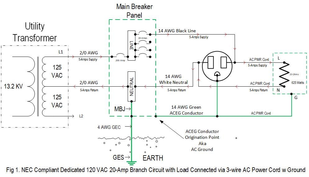
Fig 1 schematic illustrates how every NEC compliant AC branch circuit built-in homes after 1962. For clarity, I omitted L2, showing only a single dedicated 20-amp branch circuit ran to the shack with a generic DC power supply plugged in, drawing 5-amps of current. The utility uses a 2/0 AWG feeder cable from the transformer to your Service Disconnect Device located in a meter can. The MBJ bonds the GES to the service neutral. From the disconnect, four wires go to your Main Breaker Panel for branch circuit distribution.
The red arrows show normal current path. Utility Line conductor supplies the current through the resistor and returns to the Neutral conductor's to complete the circuit. Note: the ground conductor is an open circuit bonded to the chassis, with no current flowing. There is no touch voltage present on the chassis or noise in the conductor with no current flowing.
Figure 2 is the same circuit with a fault in the DC power supply. The line conductor inside the DC power supply broke loose from the on/off switch, falling into the chassis, inducing a Line-to-Ground fault. Follow the fault path current indicated by the red arrows. Current is no longer returning on the Neutral through the resistor limiting current. The ground is the return circuit conductor with very low impedance inducing 125 to 300 amps of fault current. With 125 to 300 amps flowing through a 20-Amp breaker causes the OCPD to operate instantly, clearing the fault.
Make sure you understand Ground and Neutral are NOT the same thing. A holdover from pre-1962 home construction when residential electrical systems were 2-wire. They have completely different functions. Neutral carries normal operating currents, and the ground conductors do not.
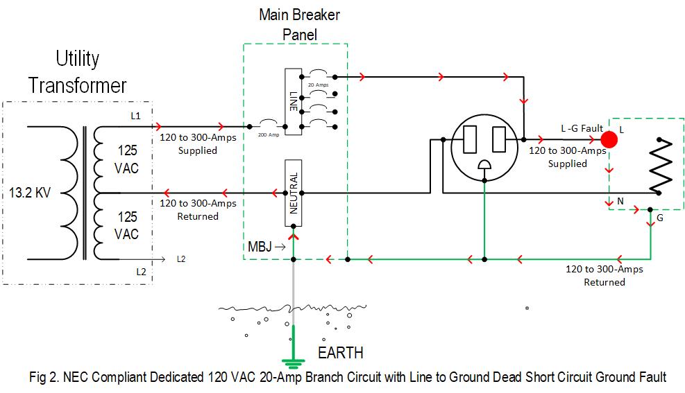
Take one last look at Fig 2. I want you to notice something. Did you miss I grayed out the GEC? I did so to demonstrate earth ground played no part in clearing the fault. You could remove the earth ground connection, float the system, and the breaker would operate normally. However, removing the earth reference would leave the chassis exposed to 120 VAC.
Key points to take away:
6. DC POWER, YOUR RADIO, AND HOME WIRING:
The three most significant challenges facing a ham radio operator are:
The objective is to isolate AC and DC power systems and remove your radio equipment from the ground loop by relocating the ACEG to the same point the shack uses. To understand what is happening, let us draw the circuit out and see what is happening.
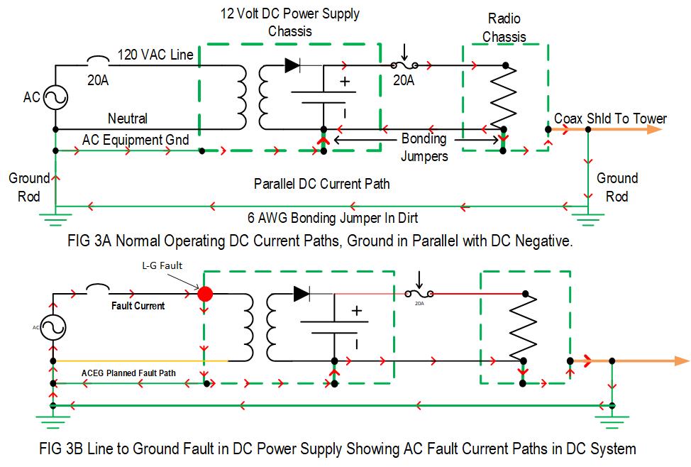
FIG 3A shows how 2-wire and 3-wire systems are incompatible. Look closely at the 2- wire system chassis (ground) and DC Negative circuit conductor and the same conductors bonded together inside your 12-volt radio equipment. That is not compatible with 3-wire systems. As you can see the red arrows result forcing normal DC operating current on ground conductors.
The result is DC flowing on AC equipment grounds, coax shields, and GES. Look what happens when I induce the same AC Line-to-Ground fault inside the DC power supply in FIG 3B. Follow the fault current paths like before. One path is on the ACEG conductor like you planned, and the other unplanned path goes through your radio equipment needlessly and can cause significant damage to your radio equipment and coaxes.
Take note. The 14 AWG ACEG conductor from the breaker panel to the wall outlet can be 30 to 100 feet in length. The unintended secondary path created is through your radio equipment using a 6 AWG conductor of approximately the same distance going back to the same point as the 14 AWG. They are in parallel. Which of those two parallel paths do you think will carry the bulk of the fault current? The 6 AWG or 14 AWG? All you need to know is how Ohm's law works; no math required. Isolate the 2- systems, and you eliminate the problem!
Lost in a ground-loop creates two more issues. One a minor annoyance generating RFI/EMI. You have a piece of wire (you radio ) bonding the two ground electrodes together with a common-mode current flowing through your EGP. The second problem can be extremely hazardous if lightning strikes nearby. Equalization current path is right through your equipment, acting as a piece of wire.
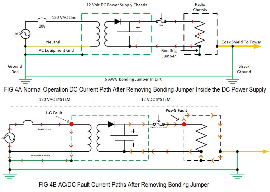
Now, look at Fig 4A and Fig 4B. I removed the bonding jumper hiding inside the DC power supply. Follow the red arrow current again. What happened? AC and DC systems are isolated. No DC is flowing on any ground conductors. Removing the bonding jumper broke the DC galvanic bond across the transformer inside your DC Power Supply. AC and DC systems are isolated, allowing you to interface your home 3-wire system to your radio's 2-wire system. The DC system can be a Grounded System, but do not use your DC power supply chassis ground because the transformer's primary side is part of the AC system, including the chassis.
7. EQUIPMENT GROUND PLANE & COMMON-MODE CURRENTS
You need to fully understand what the Equipment Ground Plane (EGP) is before we proceed. If there is a secret, this is it. Once you know the EGP, it unlocks the mystery.
To see the EGP for the first-time needs drawn out. Refer to Fig 5A, a one-line diagram of a typical ham radio system with all the toys inter-connected. The EGP input starts on the left at the AC Service ground and ends on the right where the coax exits the shack and bonded to the ground rod outside the shack. See that long daisy-chain?
You have an earth-ground at each end—one at the AC Service entrance, and the other outside the shack. Your radio system forms a single-wire circuit bonding the two grounds together. Your radio equipment is the Bonding Jumper. Two pieces of equipment have a ground, the DC power supply, and the ADU. Unfortunately, a multi- point ground. Everything between the two-grounds is a daisy-chain single-wire circuit made up of bits and pieces of ACEG, coax shields, dc negative conductor, and equipment chassis. You are in a nasty ground-loop. See it now?
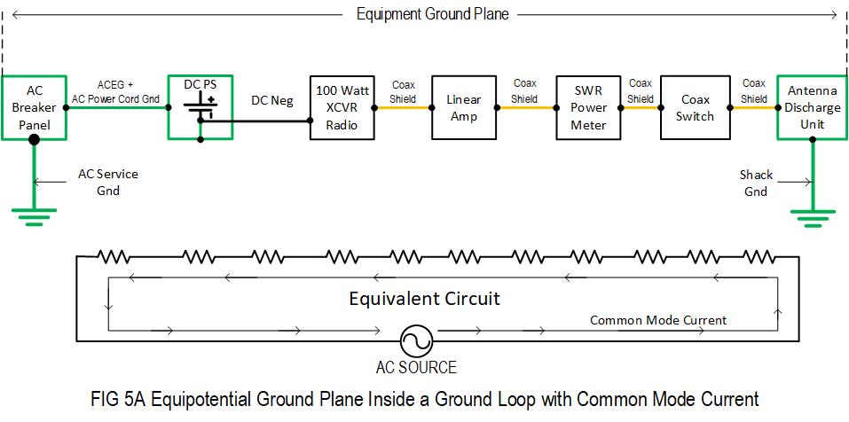
You can measure the size of the EGP with a measuring tape and electrical performance with test equipment. EGP measures some 30 to over 100-feet long, depending on the distance between the two grounds. Each piece of equipment is at a different voltage potential. There is no 0-Volt reference point because there is common-mode current flowing through your EGP with a high impedance. Ohms law is at work. Each series segment is a resistor (impedance) with current flowing, developing a voltage gradient across your EGP. Current x Resistance = Voltage.
Use a DMM, RF Volt Meter, Oscilloscope, Spectrum Analyzer, or Sweep Generator to measure electrical performance. Take all measurements by connecting one test lead to the GEC under the AC Service Meter. The other test leads outside, where the coax shield bonds to the ground rod outside the shack. Take your pick which one ground should be! While you are at it, measure the distance in feet and inches with a measuring tape.
Ideally, a DMM should measure 0-Ohms and 0-Volts AC/DC. You will see considerable resistance up to 0.5 Ohms on long circuits and have AC voltage present. Now key the mic and see what happens to DC and AC voltage? It shot way up. Ideally, all measurements should be zero, and you are nowhere close to that.
Now run an RF sweep generator and look at the impedance. It is all over the place, from 10's of ohms up to an open circuit. Ideally should be zero-ohms from DC to Light.
Now try RF voltage in both RX and TX modes. You may see low voltage in RX; in TX, you will see several volts. Should be zero-volts
Lastly, try the oscilloscope. You should see a flat line in both TX and RX modes. Good luck with that one. Now you can see all the noise flowing through your EGP. See what you have been missing? Do you want to get rid of it?
What if we moved the EGP off the equipment and relocated it where you can manage it? Say move it onto a bus-bar? If we bond the input to the output using a bus- bar where the impedance between any two points is essentially zero-ohms from DC to 1 GHz?
Bond both the Input and Output together onto a bus-bar 1 inch apart and repeat the same battery of tests. You do not need to do any test to know all test results go to virtually ZERO? The EGP is as close to perfect as physically possible. Simple and what every performance Grounding & Bonding standard specifies; a Single Point Ground.
You relocate the AC Ground on the other side of the house to the same ground the shack uses. That removes your equipment from the loop, takes the EGP off the radio equipment, and places it on a bus-bar you manage.
8. BUILD A WORKING GROUND SYSTEM:
An Equipotential Ground Plane primary characteristic we exploit is: the impedance between any two points on the plane is 0-ohms. In the real world, there is some impedance and is dependent entirely on the physical size of the plane. If we limit the size of the EGP, we keep the impedance to tolerable limits. If the plane becomes too large, it allows the impedance to become too high between two points. There would be a significant difference in potential induced across our EGP.
Many publications on the subject use a term called Ground Window. This refers to the physical size limits. The size is a 3-foot radius from the point of connection to the Absorber cable. The Absorber cable in Telecom lingo means GEC or current sink. It tells us the maximum bus-bar length you can use is 6-feet with the Absorber cable terminated in the bus-bar center. As a ham, you will not likely need anything that massive. Size limits are not an issue for most hams, and the goal is as small as possible. Where and how you land conductor's matter.
8.1 STEP 1.
Get rid of the bonding jumper inside your DC power supply. It only takes 10-minutes of your time, 30 minutes tops. Before you tear into your power supply, confirm the bonding jumper is there first with an ohmmeter. Measure the resistance between the power supply chassis and negative output with everything disconnected. If you see continuity, open the DCPS, find the bonding jumper, and get rid of it.
Astron power supplies are notorious for this, as are other low-end power supplies targeting amateur radio markets. Higher-end power supplies marketed to commercial and industrial do not bond either polarity; they float the DC output. If the user wants a Grounded System, can run a dedicated bonding jumper from the Single Point Ground bus-bar to either polarity. Hams could bond to the Negative output terminal, but there is no requirement or need to do so. You will let it float and let the radio equipment ground the DC system.
Early phone and radio systems grounded negative polarity 100 years ago. Underground lead-sheathed cables leaked DC, causing considerable galvanic corrosion and damaged cable sheaths along with the central office GES. The solution was simple, bond the positive, problem solved plus cables, and the GES receive cathodic protection with a straightforward change. You have no choice using automotive radios made for 12-volts—the radio bonds negative and chassis together, not the DC power supply.
If you are hesitant to remove the jumper inside your DCPS, do not be. NEC 250.162 expressly excludes rectifier derived DC systems from being a grounded system. 50- volts is a dividing line between hazardous and nonhazardous voltages in both equipment and electrical codes. A DC power supply is a power limited device by design and classified as a Class 1 Power Limited device of 1000 Volt-Amps or less. Equipment and electrical codes require significant impedance between Input and Output to protect the user from the low impedance utility mains. Therefore codes have less restrictive requirements for devices that are power limited to 1000 VA or less output.
Your radio chassis will have a hard-wired dedicated 6 AWG equipment bonding jumper from Station Ground. That 6 AWG goes to the same place as the 14 AWG ACEG used in the branch circuit. If there is a catastrophic failure inside your DCPS, 120-VAC primary to a 12-VDC secondary fault, the #6 AWG bonded to the radio chassis will return the fault to ACEG operating the AC circuit breaker. That is why NEC requires all systems to have a common GES in the event of a cross-system fault between two isolated systems.
Power Quality engineers use transformers to isolate electrical systems and stop common-mode currents. We can configure a Transformer as either Isolated defined as a Separately Derived Systems in NEC 250.32, or non- Isolated (non-SDS). To configure a transformer Isolated, we either float the secondary output or bond one of the polarities to the ground with a dedicated ground conductor bonded to the nearest GES access point like your Station Ground in the shack. To configure a Transformer non-Isolated, you bond one of the secondary polarities to the Transformer chassis. Either way works, but one is far better than the other.
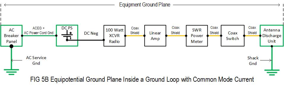
Now, look at Fig 5B, your EGP, after removing the bonding jumper inside the DCPS. It broke the Galvanic Bond across the transformer, stopping DC flow on ground wires. However, we still have a serial daisy-chain to fix. Coax shields and DC negative are not equipment grounds; they are grounded circuit conductors. All require a proper equipment ground conductor. That is why manufacturers supplied a ground terminal on 12-volt radio equipment.
8.2 STEP 2
This step will resolve four issues
Run a dedicated AC Branch Circuit to the shack on the outside of the house. You will need at least one 120 VAC circuit, perhaps two, and if you have a 240 VAC linear amplifier will require an additional dedicated 240 VAC circuit. You short the loop out; as a result, removes the equipment from the loop. The trick is you do not run and terminate the branch circuits conventionally.
How you route and configure the connections resolves the issues. You route the dedicated branch circuit outside the house, inside a protective raceway, where your coax enters the shack. Assuming you built a GES for the shack, there needs to be a rod directly below where the coax and AC circuit enter the shack near ground level. Leave roughly 4-inches of the rod above grade level for access, maintenance, and structural support. This method allows you to bond both the coax shields and AC Branch Circuit ACEG conductor together on the SPG bus-bar where they enter. That shorts out the loop removes all radio equipment out of the loop, and creates your Single Point Ground.
Many hams have the false impression NEC only focuses on safety. Telecom, data, and radio industries make up a large portion of NEC code-making panels. Numerous articles like NEC 810 target CB and ham radio operators. All illustrations in articles 250 and 810 clearly illustrate Single Point Ground. Examples show all services entering the same location with a bus-bar called an Inter-System Bonding Bar defined in NEC 250- 94. NEC gives us all the tools we need; you need to use them. That is what you are going to do. NEC 250.6(A) titled Objectional Current gives us an excellent tool to prevent objectional current. It allows you to reconfigure ground conductors to prevent objectional current from flowing on ground conductors. Also, NEC gives us 250.54, the only article with no requirements except one. CNC Machine manufacturers, ham radio users like us, along with radio and TV technologies lobbied to have 250.54 added:
250.54 Auxiliary Grounding Electrodes. One or more grounding electrodes shall be permitted to be connected to the equipment grounding conductors specified in 250.118 and shall not be required to comply with the electrode bonding requirements of 250.50 or 250.53(C) or the resistance requirements of 250.53(A)(2) Exception, the earth shall not be used as an effective ground-fault current path as specified in 250.4(A)(5) and 250.4(B)(4).
Translation, you can use any rod or wire you want to connect to the ACEG without meeting any requirements except one; you cannot use the conductors, rods, or dirt as the ACEG. The ACEG ran with the branch circuit conductors provides the planned fault path. Anything you want to add is acceptable. You can 16- penny nails for the ground rods and Cat-V cable for the ground wire. Driving rods and running a 6 AWG to an AC wall outlet ACEG complies.
For safety, the dedicated circuit needs to exit outside as soon as possible. Preferably out the back of the main panel to outside in a protective raceway. You can use PVC or EMT for the raceway. Route the circuit to the shack where the coax enters the shack. You have three options to bring everything into the shack. The first two options are for multipoint-ground, where AC service enters at a different location than the coaxes. The third option is for hams who can bring coaxes in at the AC Service entrance.
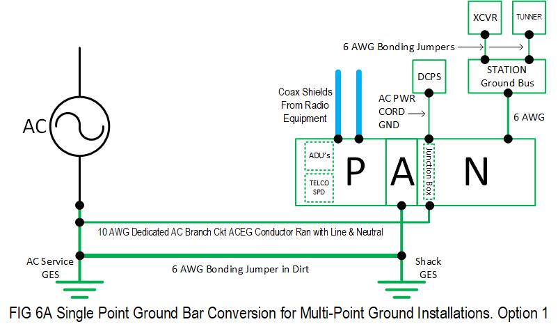
8.2.1 OPTION 1: OUTSIDE ANTENNA DISCHARGE UNITS.
Refer to Fig 6A. This option requires two bus-bars, one outside to create the Single Point Ground, another inside for Station Ground. I recommend using a non-metallic, outdoor-rated NEMA enclosure to protect connections and equipment from the environment. You will need to weatherproof.
Install an outdoor listed steel electrical junction box bolted to the SPG bus-bar using 1/4-inch x 20 hardware. How you wire and bring it in is essential. Use anti-oxidant between steel junction box and copper mating surfaces and connections. Break out the branch circuit conductors from the main breaker panel and locate Ground. Terminate the ground wire from the main breaker panel to the Junction box under one of the 1/4- inch bolts with a ring terminal. Then from the junction box (use the same bolt), run the ground wire inside with Line and Neutral conductors as usual. Use Liquid Tight or another like raceway into the back of a conventional wall receptacle next to where coax enters. When piping an AC circuit, you must use individual circuit conductors (black, white, green) and not a sheathed cable like NM-B or Romex. No shame in using an electrical contractor if needed.
Bolt surface mount ADU's to the SPG bus-bar using 1/4x20 bolts, flats, and locking hardware. Run an insulated #6 AWG conductor from SPG to SG bus-bar inside to facilitate radio equipment bonding jumpers. Code will not permit you to run AC Power with any other circuits; the branch circuit and coax cannot share the same raceway entering the shack. Run the ground conductor inside with the Coaxes, and do not use any metallic raceway for the ground wire.
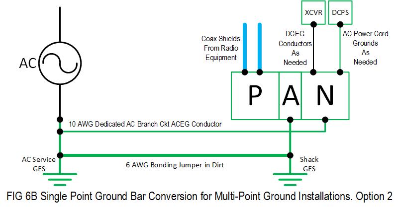
8.2.2 OPTION2 2: INSIDE ANTENNA DISCHARGE UNITS
Refer to Fig 6B. Between the two multi-point methods, this is the best practice. It enables you to bond the coax at least twice. Bonded once outside before entering, and immediately again inside. Bring your coaxes and 6 AWG inside from the ground rod together adjacent to the main breaker panel's AC branch circuit, so both enter behind the SPG bus-bar.
ADU's bolt directly to the bus-bar just like option one. I recommend you bond the coax shields to the ground rod outside using a coax ground kit. Bond the coax shield as many times as you can once out of the house. Example on top of the tower and where it breaks off the tower if using VHF and UHF antennas. Bond as many times as you can to bleed off as much energy as possible before coming inside to the ADU's.
For the AC, you do something similar as done in option 1. Use a steel electric box, either a rectangle single-gang or a square dual-gang box bolted directly to the bus-bar. Single-gang gives you one standard duplex outlet, and dual-gang gets you a quadplex outlet. I built a few for hams and found the best way to bring in the AC is right into the back of the bus-bar. The steel box has 1/2-inch knockouts in the back along with 4- holes for 1/4-inch x 20 hardware. Bring the AC right through the wall in Liquid Tight or like raceway, straight into the back of the bus-bar drilled out for the knockout. Again, wiring order matters and follows the same order.
The SPG bus-bar inside should be right where you want it, directly behind your radio bench or work station along the outside wall. Run dedicated radio equipment bonding jumpers from the SPG bus-bar to radio equipment chassis, or run a single insulated 6 AWG to a Station Ground bus-bar to facilitate equipment bonding connections without affecting performance. Strictly cosmetic/convenience and your preference.
What we accomplished running a dedicated circuit.
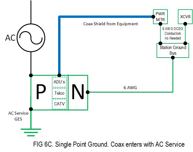
8.2.3 OPTION 3: COAX ENTERS WITH AC SERVICE
Refer to Fig 6C. Those fortunate enough to have routed coaxes and tower cables inside with the AC service have less work to do and no compromises. No special steps are required to run a dedicated AC Branch Circuits. You run it conventionally like every other circuit in the house. I recommend you use 10 AWG. Place it wherever you want it. The only detail is to use NM-B (Romex cable) and a plastic phenolic electric box for the duplex or quadplex wall outlet. This method eliminates any possibility for the AC branch circuit to encounter an incidental ground along the way, compromising the SPG.
It will require two bus-bars: one for the SPG outside where the AC service enters, and another one for the SG inside the shack to bond your radio equipment jumpers too. Note the conductor arrangement has changed to adapt to strict NEC bonding requirements for the GEC to AC Service. You cannot cut the GEC and splice it back together again; unless you have the means to use exothermic welding, brazing, or proper tooling for irreversible compression terminals. Do not cut it, and you will not have any issues with inspectors or utility companies.
The SPG will help to augment the existing GES. Use the SPG bar to bond to the newly added GES without digging up and tapping the existing GES. You get the benefit of using locking hardware and easy access. This method comes with less restrictive NEC requirements because NEC 250.54 considers them auxiliary Ground Electrodes with no requirements. You are not cutting corners, just using the SPG bus-bar to bond the existing and additional ground electrodes together.
The GEC is the single conductor exiting straight down to dirt from the meter Can/Disconnect Device. Place the SPG bar on either side of GEC as close as possible to the GEC. In fact, with one edge end passing under or over the GEC. Then it is just a matter of bonding the SPG to GEC without cutting or splicing the GEC. If you have the means to braze, exothermic weld, or have the tools to use irreversible compression terminals, please do so. Otherwise, do the best you can with mechanical pressure or clamp connectors. You want trouble-free connections, so make sure to use proper workmanship using the right hardware and materials.
ADU's and SPDs gets bonded to the SPG in their designated zones, as shown in Fig 6C. From the SPG, run your coax and insulated #6 AWG or larger conductor into the shack. Terminate #6 AWG conductor to SG bus-bar and install equipment bonding jumpers to the SG.
9. SPG BUSBAR DETAILS
When SPG architecture developed, it used intuitive acronyms to describe functions. It makes it easy for craft and technical personnel to identify the conductors' function and termination location. You likely noticed the Zones illustrated in Fig 6 drawings. Some may have heard of the zones; P, A, and N. Telecom acronym used for PANI bus-bars. We do not land conductors, and ADU's/SPD's on the SPG in random order. Each conductor has a specific zone on the SPG. According to Ohm's law, using fundamentals of current flowing through an impedance develops a voltage drop along the plane. The letters are intuitive and tell you precisely what the function of each zone is.
Producer: Conductors or equipment generating outside faults seeking earth return. These will be your coaxes, Telco, CATV, ISP, and AC Utility high-voltages (greater than 1000-volts). Utilities and lightning seek earth return
Absorber: is your earth ground connections to the GES. Your current sink for outside external faults arriving on a Producer. The planned path we provide to earth and provides our 0-Volt reference point during normal operations.
Non-Producers: Are your AC and DC Equipment Grounds used inside the shack.
Isolated: Does not apply in our application, isolated zone dropped and the "N" zone occupying that area at the far end away from Producers.
I hope you have an idea where this is going. If there are high-voltage utility or lightning faults seeking earth, the current will flow in on Producers and out on the Absorbers. No- fault currents flow across your Equipment Ground Plane through the "N" section. As a result, no voltage difference between any two pieces of equipment inside the shack. Your equipment remains unaffected.
10. SINGLE POINT GROUND BUS-BAR AND STATION GROUND BUS-BAR
Part of the fun with the hobby is building the shack. Power and grounding are critical not only for safety but also for performance. Without it, none of the other systems matter. They will not perform if plagued with power and ground issues.
There are several ways to fabricate an SPG bus-bar limited only by your fabrication skills, creativity, and imagination. There are some commercial products available called Entrance Panels. Some of the commercial offerings are quite good. Many of them use NEMA outdoor enclosures. Quality counts here.
We are not talking about using a wire or copper water pipe to make a bus-bar, as both behave like single-wire circuit conductors. It must be a plane with significant flat surface area and thermal mass. Some general rules to follow. The bus-bar is rectangular to square in shape; if rectangular in shape, width to height ratio should not exceed 6:1 Example W= 24 inches, H = 4 inches. Minimum height and width = 4-inches square. More square in shape is better than more rectangular. If you exceed the maximum ratio or minimum height, the bus-bar begins to behave more like a single-wire circuit conductor.
The plane's height and width are two dimensions providing the required surface area to ensure low RF impedance. We need some depth to determine the cross-sectional area to determine current and thermal capacities. For example, aluminum foil could not withstand a lot of current before it overheats and burns. I recommend a minimum of 1/4- inch thick copper bus-bars made for this purpose on insulated cherries. I prefer non- drilled bus-bars for customization.
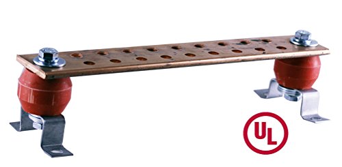
You can use heavy gauge copper sheets like some of the commercial entrance panels use. A popular size is 10 x 12 inches in a wide range of gauges and thicknesses. The minimum gauge is 10. Thicker is better, and one area you do not want the budget ax to fall on. The SPG bus-bar is the most critical element of your ground system. Use C110 grade copper, the purest form you can buy.
As already mentioned, you need to plan the layout to determine where the conductors and hardware needs to land: Producers on one side, Non-Producers on the opposite side, with the Absorber dividing P and N zones. You do not want lightning current flowing through or across your Non-Producer zone.
Exercise care when selecting hardware. Most importantly, selecting Antenna Discharge Units and all other SPD's like CATV, ISP, and Telco. The biggest mistake you can make is using an SPD that uses wire or leads for electrical connections. You want to use surface-mount devices or through-the-hole devices. Which one you use depends on how and where right-angle bends occur inside. Do not overlook other services like Telephone and Ethernet. These circuits need to go to the SPG bus-bar first to an SPD before going to your radio equipment.
Your ADU's are critical, and quality counts here. Be prepared to pay up for commercial quality names like Polyphaser and Andrews. The commercial units are either surface- mounted or through-the-hole. Surface-Mounts will use two 1/4-inch x 20 bolts with locking hardware and a large surface contact area. Through-the-Hole units will have heavy-duty threaded hardware with a large surface contact area so you can apply ample torque for a tight, secure, and low impedance connection. Consider type "N" connectors on outdoor coaxes coming in and radio coax jumpers because few commercial manufacturers offer SO-259 models. E-Bay is a good source for new and salvaged units. Many cell techs and tower crews have leftovers they sell after jobs looking to make a few perks with excess material.
My preferred construction method uses Through-the-Hole ADU's. I like a 4" x 12" x ¼" un-drilled copper bus-bar, mounted on Isolation Cherries, 4-inch AFF, on the outside wall as close to ground level as possible. Basement hams up at ground level.
My method creates a type of Hatch Plate professionals sometimes use as an SPG. The difference being the bus-bar is standing off the wall with isolation cherries rather than in the wall like a window. Another popular method is using a window opening blocked in called Window Entrance Panels. You bring both the coaxes and AC power into the backside of the bus-bar. On the other side, through the ADU's, you connect your coax jumpers to radio equipment. AC runs straight in from the backside through a 1/2-inch drilled hole lining up with the 1/2-inch knockout on the back of a single or dual gang electric box bolted to the bus-bar.
Bring a 6 AWG insulated conductor inside with coaxes from the Ground Rod, and terminate in the Absorber position between P and N zones. Do not forget other services will need an SPD. Try to avoid using mechanical and pressure clamps below grade. If you dig up the existing GES, you will see what your system will look like soon using such methods. More details when I talk about GES layout.
Connections above grade are simple using irreversible compression terminals with two- hole terminals and 1/4-inch x 20 hardware. Otherwise, use Ring Terminals made for 1/4-inch bolt hardware. Clean mating surfaces and apply a light coat of anti-oxidant to all mating surfaces. Torque every connection properly using locking hardware. You want maintenance and trouble-free connections.
Sizing ground wires is simple; use 6 AWG for all jumpers and single wire grounds. More than adequate without excessive over-kill. You will need two types of 6 AWG wire. One will be for above grade and inside the shack, and the other used outside to construct your GES.
Above grade and inside use green or black insulated extra-flexible cable stranding, preferable with tinned conductors. Standard class "B" stranding is challenging to work with and will not lay down flat and look neat without securing. Anything below grade or going to dirt, use solid, bare, and tinned for maximum service life and corrosion protection. Alternately you can use 4 AWG below grade because it is readily available and is the default conductor for new home construction.
Station Ground bus-bar follows the same methodology the SPG uses. We treat the SPG wire like the Absorber; we land it dead center on the SG bus-bar. Equipment bonding jumpers flank the Absorber working outward. Keep the SG as small as possible with a minimum of 4 x 4 inches square. Just large enough for some expansion if needed later.
10.1 WARNING:
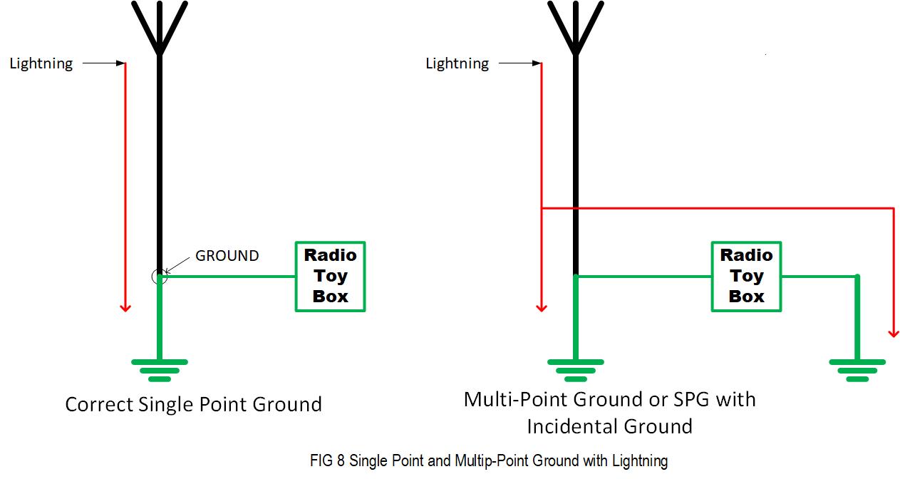
Single Point Ground offers the highest level of lightning protection and system performance possible. Pay attention and do not compromise the single point ground by introducing an Incidental Ground. Current must have a Node (point) to enter and a Node to exit to flow. In other words, it needs a door to enter the house and another door to exit. All the cables entering the protected area must pass through, bond to the SPG bus-bar, and remain isolated from incidental contact with the ground. Once inside, never see ground again. Otherwise puts you right back in a ground loop. There is no path inside for lightning to find the earth. In Fig 8, you can see how Single Point Ground operates and fails if compromised. All critical mission electronic communication facilities use Single Point Ground and rarely have any issues with Lightning and RFI/EMI.
11. GROUND ELECTRODE SYSTEM or GES:
I have not detailed the GES and will not go into any detail. Do not go down the rabbit hole pounding rods into the ground trying to achieve a low impedance spec like 5- Ohms. Rods are for power frequencies. Also known as Radials (running horizontally in dirt), bonding jumpers are for Lightning and RF. Rods couple to earth inductively behaving like single-wire circuits. When you measure Ground Impedance, you measure from DC power frequencies up to 300 Hz. Radials and bonding jumpers are capacitive coupled to earth. What does a capacitor impedance do as frequency increases? Impedance decreases, right? You do not need many rods; you want continuous runs without splices. Not to be confused with RF radials used in ground-mounted vertical antennas as a counterpoise.
Lightning has a distinct characteristic we exploit to great advantage. When lightning enters the earth, the current spreads outwardly and radially along the surface like throwing a rock into a pool of water. As lightning current travels along the surface, the soil's resistance creates a voltage drop called Step Voltage Potential. It is extremely dangerous. The distance between your feet is enough to injure, burn, or kill. However, suppose the current crosses the path of a radial. In that case, most of the current will transfer onto the conductor because the radial has a lower impedance to the earth than the surrounding soil. In other words, you can direct fault current where you want it to go, away from or around your protected area.
Science knows this for a fact from experience gained testing. Today is the primary principle of lightning protection systems. We intercept and direct the energy away from a protected area. In the 1930s through the late '50s, experiments and tests were conducted in poor developing countries with tropical climates. Home structures primarily used dirt floors. Local occupants experienced severe injuries and fatalities from frequent lightning strikes to nearby trees in villages. When lightning struck, any unfortunate soul in their home close enough to the strike and standing up on both feet was shocked or electrocuted. The voltage drop between their feet was high enough to cause injuries and fatalities. Imagine what the voltage might be with 50 feet between ground rods using your radio as the bonding jumper to equalize the voltage. Thousands of volts result in thousands of amps flowing.
Scientists and engineers discovered that a Ground Ring was extremely effective at protecting the structures and occupants inside. Locals are poor, with no means or access to #6 AWG copper or aluminum wire even if it were available. They used whatever they could get their hands on locally. Salvaged telephone wire with insulation burned off, mattress wire, baling wire, fence wire, or whatever they could obtain. The wire buried below the surface encircling the structure put a stop to injuries and fatalities. The ground ring shunted the current around the structure, protecting what was inside the ring.
Great if you can use a ground ring, but not necessary. You must realize that radials are your friends and the best tool to fight lightning. For example, say you bring your coax inside with your AC Service. Your tower is some distance away or even close by. You need to locate GEC going to the GES so you can bond to it and expand the GES. You would run a radial away from the AC Service to the tower trenched in the soil, keeping it as straight as possible. If the distance is more than 40-feet, you can sink a rod mid- span, otherwise sink a rod at the tower base for the required bond to the tower. DO NOT SPLICE RADIALS. You could call that good, meet code, and be OK. However, running another radial away from the tower, and your home is a significant improvement. More is better.
What if the tower or mast is next to the AC Service entrance or a roof mount mast? Run two or three radials away from your home in a "V" or crow-foot pattern. If you want to use rods along the route, space them no closer than 20-feet; otherwise, you can terminate a run with a rod if you wish. Just remember, ground rods are not selling what you are buying. Radials are where you want to sink sweat equity and dollars.
If you bring the coax inside at a different location than the AC service, you have more work to do. NEC 250.58 requires all ground electrodes bonded together, including anything you added for the shack. You end up with a partial ground ring because you will need to trench in the bonding jumper (radial) around the house to get to the AC Service. Exit dirt only if required to get around obstacles like driveways and walkways.
Code allows you a few options to bond all the ground electrodes together. For example, a mobile homeowner can use one of the structural steel beams. If your house has copper water piping can use outside water faucets. The best practice is to use 6 AWG copper buried in the dirt. Doing so meets and exceeds all code and operational requirements. From the shack out to the tower, proceed as above.
To sum up the GES, how you configure, connect, and what order matters. Earth or Ground Impedance is not an objective, it is the result of a properly configured system, and the impedance is what it is. You direct lightning strike where you want it to go with radials. Do not go down the earth impedance rabbit hole. Ohms law will punish you otherwise.
11.1 RF RADIALS or COUNTERPOISE.
I did not address RF Radials because most hams generally do not use them as ground electrodes where commercial broadcast AM and professionals do. Hams use RF radials as a Counterpoise, and there is no NEC requirement to bond a counterpoise. Most hams construct the RF Radials using small gauge insulated stranded wire laid on the turf. NEC requires the tower, mast, and structures grounded because we run live electrical circuits to them. Things like coax, tower lighting, rotor, etc. As stated, NEC does not address RF radials. Think about this for a moment. You intentionally do not bond the RF radials to the GES, only connecting the coax shield. Do not make this mistake. Guess what the bonding jumper is connecting the two? Your coax shield, right? Do you want to use your coax shield as a bonding jumper intended to carry lightning?
Ideally, bond your coax as many times as possible outside the shack to bleed off as much charge as you can before it arrives at the shack. Commercial AM broadcast towers use RF radials just like hams. The difference is they do not use small insulated conductors. They use larger bare conductors at grade level. Not only does it function as the Counterpoise, but it affords excellent lightning protection. Do not bury RF radials, just embedded enough to protect them from lawnmowers. Dirt is a poor conductor, and RF energy cannot penetrate the soil. Bury them, or to few radials, and you made an expensive earthworm sauna using RF energy to heat the dirt. The vertical half of the antenna is looking for its counterpart circuit conductor to complete the circuit for RF energy to push off.
The takeaway point is it is OK to use insulated radials if you wish. It will work for the intended purpose, but if you use radials, bond the radials to the GES. Do not use your coax to do that for you. It works great until there is a lightning event and you discover you have coax thermal damage.
11.2 GES TERMINATIONS.
The biggest challenge facing you is augmenting your homes' existing GES. You do not need to dig it up unless you want to inspect it. Mechanical and pressure clamps all fail in a short time. Connections fail when exposed to the elements. NEC has stringent requirements for the GEC, as previously stated. If there is a utility high-voltage primary to a secondary fault in the transformer, it comes in on the Neutral, and earth is the return path to the source.
NEC 250.64 (C) Continuous. Except as provided in 250.30(A)(5) and (A)(6), 250.30(B)(1), and 250.68(C), grounding electrode conductor(s) shall be installed in one continuous length without a splice or joint. If necessary, splices or connections shall be made as permitted in (1) through (4):
- Splicing of the wire-type grounding electrode conductor shall be permitted only by irreversible compression type connectors listed as grounding and bonding equipment or by the exothermic welding process.
- Sections of bus-bars shall be permitted to be connected together to form a grounding electrode conductor.
- Bolted, riveted, or welded connections of structural metal frames of buildings or structures.
- Threaded, welded, brazed, soldered, or bolted-flange connections of metal water piping.
Above is useful information to help you. It explains why I said keep radials continuous. You do not want to cut or splice the GEC because it is grand-fathered in the code and not subject to further inspections. To expand the GES, tap the GEC above grade, where you can maintain the connection. If you have electrical work that requires electrical inspection, the inspector would not even look at what you added because it is auxiliary (optional) and not required. The only thing the inspector cares about is the GEC that came with your house. Unless needed, do not disturb it.
Now you know the radials are the most effective against lightning. When you run a radial, do not cut or splice it; run it out all the way. The longer, the better. Any rod along the way with a failed connection is not going to degrade performance much. Splice the radial at every rod intersection, and a failure is a significant problem. You do not care if a rod fails, but a failed radial is severe.
You know to avoid mechanical pressure connectors and clamps, but you may not have a choice. The code gives you some options. For example, NEC forbids solder if the electrical and mechanical connection relies upon solder. If one were to take a listed Grounding Connector, use it as intended, then use a torch to solder might work. Even better if brazed. Connections are critical. Pay attention to details.
Good luck, you are on your own now and know what to do.
12. YOUR VEHICLE RADIO POWER:
No amateur radio grounding and bonding guide would be complete without discussing putting a radio in your vehicle. That is why your radio came with automotive mounting hardware. Automotive is a 2-wire power and ground architecture where negative is both a circuit conductor and ground. Many hams operators and most radio manufacturers make a crucial mistake connecting radio power. Both failed to look at the circuit they create when you take the radio negative battery conductor and run it directly to the battery negative term post. NEVER EVER DO THAT! You think the Ground Loop in your home was nasty; this is the father of nasty Ground Loops and extremely hazardous.
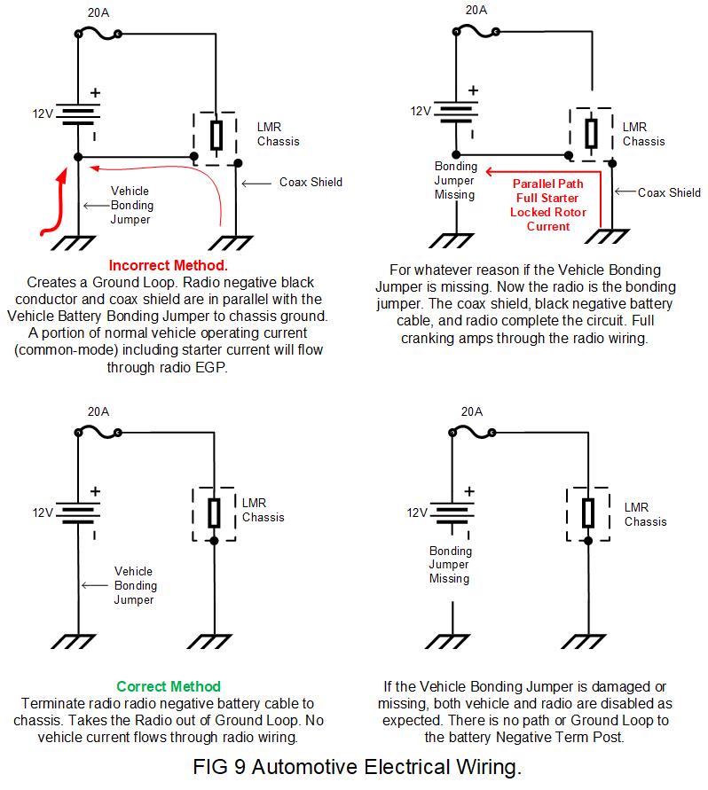
A vehicle's power system is simple. It uses one-wire to bond the battery negative term post to the vehicle chassis. Pop the hood and look-see at the battery negative term post. You will find the Bonding Jumper connected to the vehicle chassis electrical hard- point secured with a 10 mm bolt and dragon tooth lock washer. All vehicle currents return to the battery through this single conductor, including engine cranking current. If you connect your radio's battery negative wire directly to the battery negative term post, you will place your radio in parallel with the vehicle's bonding jumper. Refer to Fig 9.
Being in parallel means a portion of all vehicle current, including engine cranking current, will flow through your radio. Look at the current path. Coax Shield > Radio Chassis> Radio Negative Battery Wire > Battery return Post completing the loop. It will generate RFI/EMI issues you will never fix. Vehicle current is flowing right through your EGP. Roughly 5 to 10% of all vehicle current is using your radio as a power wire. That includes a portion of 300 to 500 amps starting current on cold winter mornings. Talk about common-mode currents?
Time to fix that time bomb if this is your radio. The loop is just a minor annoyance during normal operations. No one gets hurts if both TX and RX are unusable due to noise. Suppose for any reason, maintenance, normal wear and tear, or anything happens to the vehicle bonding jumper and comes loose. If that happens, you will have significant equipment damage when you start your vehicle and possible vehicle fire. Your radio is now the Bonding Jumper for your car. All vehicle electrical current is using your radio as a wire. You get inside, insert the key in the ignition, everything comes on normally, and you crank the engine. You hear the engine crank slowly like a low battery, and the cab fills with smoke.
You panic, turn the car off and get out asap. Once the smoke clears, you investigate and see three clues:
That is when you realize the radio was in parallel with the vehicle bonding jumper. When you tried to start the car, the starter current burned everything up. You solved the mystery of why the positive wire and fuse came out unscathed. No-fault current ever went through it. It was the father load of Common-Mode Current flowing through your EGP. Surprise! You forced a few hundred amps engine cranking current right through your radio. Where, how, and in what order you connect things matter.
The intent is to minimize voltage loss by directly connecting both positive and negative radio to the battery term post. Unfortunately, not even the radio manufacturers bothered to look at the circuit and how it interacts with the vehicle.
You can connect the battery negative anywhere you want except the battery negative term post. Essentially you accomplish the same thing if you use the same chassis hard- point the vehicle bonding jumper uses. Pull the bolt, place your ring terminal on top with anti-oxidant, and replace the 10-mm bolt and locking hardware. Not necessarily the best practice, but it works and is safe. Doing so only satisfies one of two requirements. It keeps voltage sag under control when we transmit. It fails by making your EGP larger than necessary. Remember in a loop where the equipment ground plane begins and ends? It starts where we connect negative and ends at the antenna coax shield bonded to the vehicle's chassis.
Ideally, you would like to use the same point to connect both the negative and the coax shield to the same point to get out of a ground loop. Unless you use a special engine compartment offset antenna bracket for the antenna to mount by the battery is not possible in a vehicle. You have no choice.
Many commercial LMR radios isolate the chassis from both polarities and connect directly to both battery term posts without placing the radio in a ground loop. With the radio isolated from the vehicle chassis, the only ground connection is via coax shield.
The negative radio lead should be as short as possible, measured in inches, not feet. Determine the radio's location in the vehicle, for example, under the driver or passenger seat. Initially, just run positive out the door or a rolled down window with the hood open and connected directly to the battery positive term post using a temporary jumper for testing. Unroll the black negative wire and terminate with a spare ring terminal temporarily. Connect negative to the nearest chassis hard-point like a seat-bolt. Look closely under seats because the auto manufactures equip heavy-duty chassis grounds for heated seats, power seats, and add-on equipment like Inverters and Audio Power Amps.
Turn on the radio, set to FM or AM with full TX power. Measure the voltage at the radio input in RX mode and battery term post and record voltages. Key the microphone and re-record the voltages; if the battery voltage sag is less than 1/2-volt, pass go. If greater than 1/2-volt, move forward toward the engine compartment and retest. Repeat working your way toward the engine compartment. Before you go through the firewall, you should find and use one of the auto's chassis grounds. Easy to spot by looking for where the manufacturer used by spotting the ring terminals with green or black wires. If you must go to the engine compartment, terminate where the vehicle bonding jumper terminates on the chassis by using the same bolt.
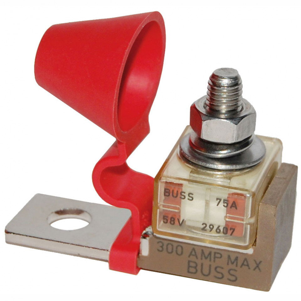
After you determine the radio negative ground point, you are ready to install. The radio's positive wire goes directly to the battery terminal post with an in-line fuse installed as close to the battery as possible. A great product is a Marine Battery Fuse (MRBF) with a Marine Terminal Fuse Block like you see in Fig 10. It bolts directly to the battery terminal post equipped with a 3/8-inch stud to facilitate ring-terminal connection. Do not run radio any cables with vehicle wiring. Where they must cross paths, do so at right angles. Keep positive as short as possible, cut to length, and do not roll up excess wire. Pop the door floor rails off. You will find empty raceways exiting behind kick-panels on either driver's or passenger side.
Use ring terminals, anti-oxidant, and pay attention to connection details like proper crimping and bolt torque. It is again crucial to keep the negative as short as you possibly can. It keeps the EGP as small as possible, just like in the home applies. Do not forget the coax keeping it as short as possible and away from vehicle wiring to the extent possible.
13. CONCLUSION:
Well, I hope you made it this far and found this document useful. Time to do some math; it will show you how simple it is. We used Ohm's Law as it applies to series and parallel circuits. We took two circuits, shorted one out, and placed them in parallel.
The first circuit we shorted out was your Single Wire Circuit used as your Equipment Ground Plane, some 30 to 100 feet in length. A long series-connected daisy-chain bonding two grounds together, placing you inside a Ground Loop. The impedance is going to be very high. If we swept from say DC to 500 MHz would see at 1 to 3 MHz could be as low as 30 to 40 Ohms if resonant, and up to several thousand ohms in between resonate dips. Using a very conservative 100 Ohm model on the frequencies of interest will demonstrate what is happening.
We took the 100-Ohm circuit and shorted it out with the SPG bus-bar. We arranged it so that the Input of the EGP (the ground pin on the DC Power Supply) lands 1-inch away from the Output to the ADU. The impedance of the parallel second circuit is realistically lower than 0.0001 Ohms.
We have two parallel circuits. One has an impedance of 100-Ohms, in parallel with the SPG 0.0001-Ohms. That forms an impedance ratio of 100 / 0.0001 = 1,000,000 : 1. Every 1,000,000-amps of current flowing in the SPG bus-bar results in 1-amp of current flowing in the radio EGP. You have a very quiet ground system hardened and can survive significant amounts of outside fault currents passing through your EGP, not allowing them to come inside.
Suppose you take a small direct strike of lightning on the antenna producing 1000-Amps of current flow in your SPG bus-bar. Of that 1000 Amps, you will have 0.001 Amps flowing through your EGP with an impedance of 100 Ohms developing a voltage drop of 0.1 volts. Up strike current to 10,000 Amps results in 1-Volt across your equipment. If it not for the crash of sudden noise in your receiver audio and the sonic boom of thunder shaking the shack, you and your radio would never know anything happened.
You made the father of Common-Mode Choke. None like you can ever replicate with coax, wire, and ferrite cores. Your Common-Mode Choke does not saturate, has a bandwidth of DC well above any frequency a ham uses. Common-mode current attenuation is roughly a minimum of 50 dB, realistically higher because we used a conservative 100 Ohms as the model. If the real impedance is 1000-Ohms, this results in 60 dB attenuation from DC to 1 GHz. Not perfect, but as good as it gets.
The moment you terminated the dedicated ACEG to the SPG bus-bar did Ohms law magic by shoring out the ground loop you were in and removed your equipment from the loop. You relocated the ACEG to the SPG bus-bar and transferred 99.99% of the Ground Plane off your equipment onto the SPG bus-bar. The only other thing we did was remove a bonding jumper inside your DC power supply to Isolate AC and DC power systems braking the galvanic DC bond across the transformer inside your DCPS.
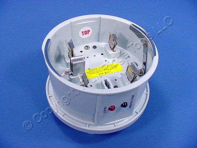
One last thought, your radio antenna and coax are the second most likely source to produce a surge event. The most likely cause of a significant event is the high- voltage utility and service providers like CATV and Telco. A point of use SPD like a power term-strip Is not going to protect you because they do not have the capacity and intended to be a second line of defense. It would be best if you had a whole-house SPD with a UL-1449 listing. Do not use SPD's that require wires or cable for connections. You want a device like Fig 11. A meter collar device, easily installed by unplugging your electric meter, plug in the Collar, then plug the meter back in. No tools required.
I leave you with this. Bond everything below ground together, bond everything above ground together, then bond the two together at one single point.
Good luck.
Contact Information:
The author can be contacted at dereckbc [ at ] gmail [ dot ] com.
Article text, layout, and images © Copyright 2020 By Dereck Campbell KF5LJW.
Some text, HTML, and conversion to Repeater-Builder format by Robert W. Meister WA1MIK.
Back to the top of the page
Back to Tech Index
Back to Home
This article was created 18-Nov-2020.
This web page, this web site, the information presented in and on its pages and in these modifications and conversions is © Copyrighted 1995 and (date of last update) by Kevin Custer W3KKC and multiple originating authors. All Rights Reserved, including that of paper and web publication elsewhere.