Back to Home
by Matt Lechliter W6XC

|
Up one level Back to Home |
Pre and De Emphasis - Explanation and Assistance: Running the Numbers by Matt Lechliter W6XC |

|
Background:
Although there are plenty of articles on this site (and others) dealing with these subjects already, more perspectives usually are of help. In these, much useful information and history is provided. However, I was interested in mathematical formulas to accompany them, and assist me in tailoring circuits to sound their best, within my preferences. I shall attempt to present working formulas here, to supplement the well-written presentations which are already here. I also must admit that I am not an expert, and do not yet have a degree. What I present here is based upon what I have been able to do in educating myself--asking questions of those who have long time experience, experimenting on my own, and reading about the principles of electronics. If any of this information is in error, please do not hesitate to contact me in order to clear up my misconception(s).
Pre and De-Emphasis certainly have their purpose. Early in the use of FM, the preponderance of communications equipment actually utilized PM, or Phase Modulation, and not the more commonly perceived sibling, Frequency Modulation, since PM was more readily achieved at the time. As we may or may not know, Phase Modulation (hereafter referred to as PM), has an inherent change in deviation with respect to modulating frequency, increasing by 6 dB (*2 with respect to voltage) for every octave. This is pre-emphasis. Frequency Modulation, however, does not have this quality. Only amplitude causes a change in deviation, making true FM "flat." True-FM systems were then made to accommodate the established standard, by adding a pre-emphasis stage in them. This made True-FM comm. systems and the existing PM comm. systems compatible. FM receivers must, therefore, accommodate this characteristic. This is one area where the use of de-emphasis comes into play. The second is in repeater/remote base system construction, where one wishes to have "flat audio throughput," and there are PM transmitters used. This is presuming that flat audio is achieved by utilizing raw and unprocessed discriminator/detector audio, which is subsequently injected into the transmitter's modulator circuitry directly, bypassing the factory's mic amp, clipper, and splatter filter, which should then be replaced by a compressor (limiter) and an appropriate lowpass filter, so that one remains a good adjacent-channel neighbor. A good example of a compressor is found here on this site. Please note that this is based upon my personal preference and experience. Your mileage may vary, and everyone has differing tastes.
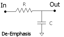
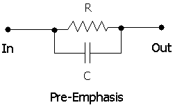
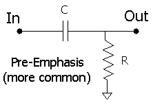
Entertainment/broadcasting typically has pre-emphasis begin in the neighborhood of 1.5 kHz to 2 kHz and continue upward at a ~6dB per octave rate. This is a 75 microsecond pre-emphasis. Two-way communications equipment has its pre-emphasis set to begin at a lower frequency, and has variance between differing equipment manufacturers. Simple RC circuits can be used, although other methods have also been employed. Resistance and Capacity are effective due to the fact that the AC resistance of the capacitor (impedance) becomes lessened as the frequency increases. When at the "crossover" frequency, the AC resistance of the capacitor equals the value of the resistor. This is also referred to as the "cutoff" or "corner" frequency. When employed in a pre-emphasis role, the 2 elements can be placed in two configurations, shown later in this article: in series (C in series with R to ground), or in parallel; in de-emphasis, they effectively are in series, an AC voltage divider. If you modify any transceiver for packet use, or you are working to achieve a "flat audio environment" in a repeater/remote base system with a mixture of FM and PM transmitters, you'll most likely be faced with having to accommodate "emphasis."
The Numbers, shall we?
We come to the question point blank, "What is 6 dB per octave?" Firstly, an octave is when a frequency doubles. In 1200 baud VHF & UHF packet, the modems use tones of 1.2 kHz and 2.2 kHz. This isn't exactly an octave, but is in a reasonable neighborhood thereof. The 2200 Hz tone should be ~6 dB higher in level than that at 1200 Hz. The real increase in dB is closer to 5.45 dB, but 6 dB is close enough for our purposes. Calculating the frequency response characteristics of the circuits is not overly difficult, as we shall see below. Now, to the formulas! Yes, number crunching. It's time to use that scientific calculator.
Some basic definitions of variables:
t = time constant in microseconds
R = Resistance in Ohms
C = Capacitance in microfarads
Fc = Crossover Frequency in Hz
pi = The value of pi (3.141592654)
Followed by the formulas themselves:
t = R*C
t = 1,000,000/(2*pi*Fc)
Fc = 1,000,000/(2*pi*t)
Fc = 1,000,000/(2*pi*R*C)
R = t/C
R = 1,000,000/(2*pi*C*Fc)
C = t/R
C = 1,000,000/(2*pi*R*Fc)


In the pre-emphasis role, the resistor and capacitor are placed in parallel, and this combination is then placed in series with the audio to the transmitter/exciter at the appropriate point. In the de-emphasis role, the resistor is placed in series with the receive audio path at the desired point, and the end of the resistor closest to the last device in the series (TNC, speaker amplifier, controller, exciter input, etc.) is bypassed with the capacitor, i.e. the cap is connected between this point and the ground rail. Pay careful attention to the resistance value selected. The input capacity of the port involved will also affect the results. Definitely be aware of the input capacitance. If it is already .01 uF, a series resistance of 10K Ohms would put the response at greater than 6 dB per octave, and yield too much high frequency roll-off without use of the additional capacitor in the RC! Beware of those proverbial electronic "gotchas."
Another one of them is in the circuit examples above. In most two-way and other applications, the series RC pre-emphasis method, vice the paralleled element method, is used to obtain the desired effect. When placed between two stages, the paralleling method does not work. Instead, the C of the parallell and forward stage's resistance to ground determines the corner frequency, not the R and C themselves in unison, which throws everything off, unless the resistance matches what is desired. (Don't look for it)
I would advise using a resistor value approximately equal to the impedance it will be looking at. If one were to place a de-emphasis resistor in series with an audio signal feeding a device with a 600 Ohm input, they probably wouldn't want to use a 22K Ohm resistor -- unless they had a significant signal surplus and low input capacitance. Running the numbers indicates that they should see approximately a 40 to 1 reduction in signal voltage. With a 600 ohm input, a decent value would be a 470 Ohm resistor; this would reduce the audio by something less than half. The same holds true on the pre-emphasis side of this universe. I shall concede that sometimes it is acceptable to split the difference on a resistor value if one is feeding a low impedance from a high impedance, and has a surplus of signal voltage, in addition to a low input capacitance. Experiment, and see what happens. If the results aren't satisfying, use another combination.
Also, do remember that the impedance of the source fed into the R & C circuit should be relatively low, and its output should drive a higher impedance load. The formulas need be changed to accomidate additional impedance influences if this is not followed.
Choosing component values based upon situational variables
Here are some examples where we put my rambling into practice:
Example 1: Improving DTMF decoding with raw discriminator/detector audio as the source
In this situation, one desires to improve the DTMF decoding reliability of a device that is using discriminator/detector audio. Since discriminator audio is already emphasized, a de-emphasis network is needed to "roll off" or attenuate the high frequency components, including white noise that is interfering with the decoding by swamping the decoder. The frequencies for DTMF digits range from ~700 Hz (actually 697 Hz) to ~1600 Hz, so you want to start rolling off the audio at or above the highest of them, at the 1600 Hz point here:
Fc = 1600
R = 10,000 (working with a presumed 10K input impedance)
C = 1,000,000/(2*pi*10,000*1600) = 0.01uF
This RC would deliver nearly 6 dB reduction at 3 kHz. Alternately, choosing a slightly lower crossover frequency could be used to achieve more noise reduction at 3 kHz.
Recommended Method: In order to avoid too much "twist" in decoding, which can also prove to be a problem, we choose a crossover of 700 Hz. This accomidates our desire to reduce the influence of noise, and take care of pre-emphasized user DTMF. Since most communications equipment pre-emphasizes DTMF, this makes the most sense. This option would best be used over the above, although both are included to suit differing situations. It all depends on your decoder's tolerances, but why have "twist" if it isn't necessary?
Fc = 700
R = 10,000 (10K working input Z)
C = 1,000,000/(2*pi*10,000*700) = 0.022uF
Example 2: Phase-Modulated Transmitters and Accommodating Raw Detector Audio as used in Flat-Audio systems
This case is where audio from your transmitter sounds too 'tinny' or restricted. It is desired to de-emphasize the audio before it is injected into the transmitter's modulator. To help bring out the lower end of the speech pass band, set a crossover frequency much lower, say around 212 Hz. This presumes that one is unsure of the modulator's input impedance.
Fc = 212 Hz
t = 1,000,000/(2*pi*212) = 750 uS (microseconds)
Choosing a standard value for C:
C = 0.1 uF
R = 1,000,000/(2*pi*0.1*212) = 7500 Ohm (7.5K)
Or, let C = 0.047 uF, then
R = 1,000,000/(2*pi*0.047*212) = 16,000 Ohm (16K)
Since 16K is an odd value, but lo, a 15K resistor is in stock, we
recalculate having substituted...
t = 15,000 * 0.047 = 705 uS
Fc = 1,000,000/(2*pi*705) = 225 Hz
Here, we obtain a difference that is most likely negligible.
Example 3: Pre-Emphasizing or De-Emphasizing Audio to the Control System (lessening or increasing the effect of upper-freq. roll-off in its audio chain)
Here, one desires to pre-emphasize or de-emphasize audio fed into a controller with a 10K Ohm input impedance, using a standard 75 uS time constant:
Select R = 10,000 (10K) to have significant effect with input impedance considered.
Fc = 1,000,000/(2*pi*R*C)
Fc = 1,000,000/(2*pi*75) = 2122 Hz
C = t/R
C = 75/10,000 = 0.0075 uF
And there we have it.
Working with Operational Amplifiers
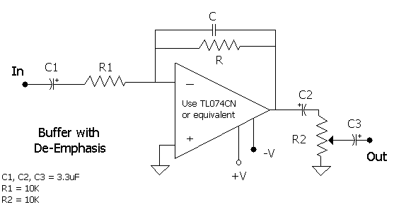
Adding new flavour to the subject is the introduction of op-amps. They allow a little more flexibility. The same equations as in the above examples still apply here, yet the placement of components is a little different. Below is an image to demonstrate:

Another example by N1UEC is found here. In this case, we find C and R in parallel. Yet, the same equations still hold. The other components R1, C1-C3, and R2 primarily determine the lower frequency cutoff (C1-C3) and the gain (R1 with respect to R2; in the drawing above they are equal, providing unity gain). The values provided should yield adequate results for your application, although they can be changed. This example is also meant to use a dual-supply configuration, although it can be modified to be a single-supply design with minimal effort. In this case, one would tie the non-inverting input to a voltage divider consisting of two 4.7K resistors, with a 10uF electrolytic bypassing to ground. The voltage supply pins of the opamp would then be V+ and GND respectively. My recommended supply voltage here would be +12V. When building it as depicted, +/-9V is easily obtained with a 7809 regulator and an ICL7660 neg. DC voltage generator. As a note, I prefer to use sealed multi-turn potentiometers whenever possible. Those of the ten, 15 and twenty-turn variety work well. Let us proceed to some working examples with this circuit:
Examples with standard component values:
In the first item, we choose C = .0068 uF and R = 470K Ohms. This yields a cutoff frequency of ~46 Hz. These values are also used in the N1UEC circuit's feedback-loop arrangement.
Fc = 46 Hz
Fc = 1,000,000/(2*pi*470,000*.0068)
R = 1,000,000/(2*pi*C*Fc)
C = 1,000,000/(2*pi*470,000*46) = .0068
The second works with C = .001 uF and R = 1MegaOhm. Our cutoff frequency is then ~159 Hz.
Fc = 1,000,000/(2*pi*1,000,000*.001) = 159 Hz
R = 1,000,000/(2*pi*.001*159) = 1,000,000 (1Megaohm)
C = 1,000,000/(2*pi*1,000,000*159) = .001 uF
With the third, we maintain a closeness to the 159 Hz cutoff, and select differing component values based upod our C being .1 uF. This is also an effectively "unity gain" scenario when looking at the relationship between R1 (as given) and our calculated feedback R.
Fc = 1,000,000/(2*pi*10,500*.1) = 150 Hz
R = 1,000,000/(2*pi*.1*150) = 10,500 (10.5K) [use a 10K resistor with a 500
or 470ohm resistor in series for the feedback loop]
C = 1,000,000/(2*pi*10,500*150) = .1uF
Finally, example four: This time, the aim is a lower corner frequency while still using common components, and having a decent amount of gain to compensate for the "effective loss" of level due to the de-emphasis. We arrive at ~60 Hz as the cutoff.
Fc = 1,000,000/(2*pi*56,000*.047) = 60 Hz
R = 1,000,000/(2*pi*.047*60) = 56,000
C = 1,000,000/(2*pi*56,000*60) = .047 uF
These same principles can be used to suit your specific desires in any similar circuits.
In Closing...
I would hope that this is of help to all who read, and acts as a nice supplement to the information already presented detailing the history and principles of two-way and broadcast FM & PM communications. I have gathered much of the information from a variety of sources, including what experience I have been able to obtain in experimenting, and applying what I had read about in the real world. All comments are welcome, good or bad. I like to receive feedback. This is my first article, after all, and it would be nice to see how it is received. It is likely that I shall add more to this with time. Please do enjoy.
Copyright October 31, 2002 Matt Lechliter W6XC
My e-mail data is good in the QRZ.COM database
HTML Publishing © October 31 2002 Kevin K. Custer W3KKC
All Rights Reserved.
Back to the top of the page
Back to Tech Index
Back to Home