
|
The Motorola Portable Test
Set Page
Information on several vintages including the P-8501, TU546 series,
S‑1056 / 1057 / 1058 / 1059 series, R1033,
RTX4005 and several base station / repeater test sets.
|
|
|
R1011B 40V 40A DC Power Supply Manual 2.4 MB PDF
|
|
|
R1013A SINAD Meter Manual 401 kB PDF
Donated by John Crabtree KCØG. 6881069A81
|
|
|
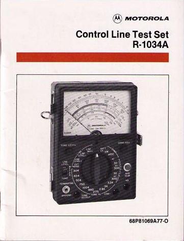
R1034A Control Line Test
Set Manual 720 kB PDF
Photo of the R1034A
tester Manual 6881069A77-O
Note that the R1034A Test Set and the R1034B Control Line Test Set are two very
different products inside despite the fact that they have a similar purpose and
an almost-identical model number.
Many dispatch systems had the base station or repeater at one location and the
control point at another. Setting up or maintaining the connecting phone line
required the ability to make both DC and AC measurements. Motorola and Triplett
together designed the Model R1034A Control Line Test Set, and the mixed background
of the Motorola 2-way engineers and the telephone telecommunications background
of the Triplett engineers shows in the design. This unit is essentially a specialized
AC and DC VOM and an audio generator all in one ruggedized package (by using the
existing housing from the Triplett 630-series VOM they could take advantage of
the existing accessories including probes and carry-cases). The unit measures
telephone line current, telephone line noise, DC resistance and both AC and DC Volts,
and all measurements are using ranges that are optimized to telco control lines. This
test set will also send audio tones at an adjustable level and measure received tones
in dB on the meter. A pushbutton adds a 10dB attenuator in line. A switch on the
lower left of the panel selects bridged or terminated mode. The unit was built
into a sturdy protective carrying case with a pocket in the lid for the book and
the probes, and a snap-hook shoulder strap for carrying. There is a 1 amp
fast-blow fuse that is in line with the volts and ohms measuring circuitry inside
the battery compartment. DO NOT replace it with a slow-blow fuse. The test set is
powered by two common 9 Volt batteries and one D-cell battery - and the
second 9V battery is hidden behind the "D" cell!
Before you buy a second-hand R1034 make sure that you open it up and check for
corrosion caused by leaky batteries (this is the voice of experience speaking
on the fuse and the battery...).
|
|
|
R1034B Control Line Test
Set Manual 836 kB PDF 6880310B60-O
Note that the R1034A Test Set and the R1034B Control Line Test Set are two very
different products inside despite the fact that they have a similar purpose and
an almost-identical model number.
This is a redesigned and updated version of the above. Triplett sold this unit
as the "Model 4 Subscriber Loop Test Set" for doing telephone circuits. The text
portion of the manual was scanned by Eric Lemmon WB6FLY, Richard Carlson N9JIG
provided the schematic, and Bob WA1MIK cleaned and merged the whole thing. Also
note that there are five batteries in this unit: two 9 volt (B1 and B2),
two 22.5 volt (B3 and B4), and one 1.5 volt C cell (B5).
|
|
|
Triplett Model 4 Control Line Test Set
Manual 860 kB PDF
This is the manual for the Triplett version of the Motorola R1034B test set above.
It was scanned by Richard Carlson N9JIG and supplied to repeater-builder as three
files.
|
|
|
R1100A Code Synthesizer Operator's
Manual 7.2 MB PDF
A PL, DPL, single tone and 2-tone test generator that goes up to 10 Khz. Power is 12vDC or 120vAC.
|
|
|
R1150 / R1151 Code Synthesizer II Operator's
Manual 1.5 MB PDF
This is manual 6880310B03-B dated October 1994 that covers the operation of the
R1150, R1151, R1150A, R1150E and the RLN4504A memory upgrade kit (there are no
schematics or technical information). The first 28 pages in the PDF file are the
R1150 manual, and the last 8 pages are the R1151 addendum. Courtesy of Dan Fargo KB3EMH.
|
|
|
S1051B, S1051C, and S1053C Transistorized Voltmeters
S1051B Manual 857
kB PDF donated by Eric Lemmon WB6FLY. 6881003A15-O
S1051C and S1053C
Manual 2.9 MB PDF 6881021A05-C
This is an AC voltmeter that covers 1 millivolt (-72 dBm) to 300 volts (+52 dBm) in
12 ranges, and is +/- 2% from 50 Hz to 300 kHz, or +/-3% from 20 Hz to 1 MHz.
The S1051 is battery operated only and used a single 8.4 mercury battery (Mallory
TR-136), which is no longer available. It works just fine with a standard 9 volt
battery with a 470 ohm resistor in series with it. The S1053 series is AC or
Battery operated, the AC adaptor provides 9 volts AC. It's easy to convert an S1051
into an S1053 by adding a leftover 9v DC wall wart and the missing components (the
"C" version manual covers both units).
The SKN6001A is the "official" test lead kit that is used on several Moto measuring
devices. It is a 30 inch length of RG-58-style shielded cable with a standard 2-pin
bannana plug on one end and a pair of insulated alligator clips on the other.
|
|
|
S1067 Transistorized Audio Oscillator
Manual 4.6 MB PDF
The manual calls for a no-longer-available 22.5 volt Burgess battery. An
Eveready 763 (NEDA 710 or HS6571) battery works fine.
|
|
|
S1305A 40V 40A DC Power
Supply Manual 2.5 MB PDF
This is the Ratelco PS-8 supply, which was rebranded and sold by Motorola.
|
|
|
S1318A, S1319A, S1320A, S1321A
and S1329A Signal Generators Manual 12 MB PDF
|
|
|
S1318A, S1319A, S1320A, S1321A
and S1329A Signal Generators Manual 16 MB PDF
A better quality version of the above manual.
|
|
|
S1327A Service Monitor Instruction
Manual 6.7 MB PDF Donated by Jeff Parker WA1WXL
A basic communications service monitor that accepts plug-in modules to provide
analog metering and visual display of deviation. It also can utilize plug-in
preselectors to enhance sensitivity and selectivity. .
|
|
|
S1339A RF MilliVoltmeter Instruction
Manual 2.1 MB PDF
It's the same as the Boonton 92E click here for
a photo, because the S1339A was just a relabeled Boonton.
|
|
|
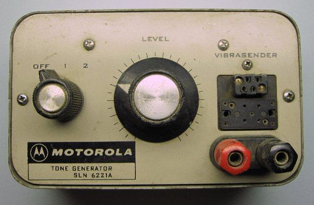
SLN6221 Tone
Generator Manual 294 kB PDF
Smaller file 203
kB PDF Photo
This is a reed-based test tone generator designed to plug into a service monitor.
The upper socket is for the small reeds, the lower socket for the "copper banana"
reeds. 6881114A02-B
|
|
|
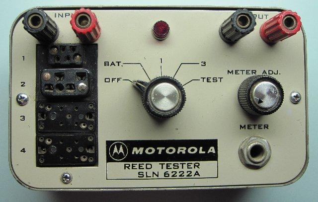
SLN6222A and SLN6222B Reed
Tester Manual 587 kB PDF
Photo
This unit uses a no-longer-available 6.5-7 volt 1000 mAh mercury battery that is
0.662" diameter and 3.245" long. The battery may be one of the following brands
and types: Eveready E135, Mallory TR-135, or Ray-O-Vac T-135. If you have one of
these you may end up using an external battery pack or a DC wall-wart style power
supply. There is enough room inside the case that you could add a 6v three-terminal
regulator with one silcon diode to raise it 3/4 volt (which would deliver 6.75
volts), then power it with a 12vDC source. 6881114A04-D
|
|
|
SLN6413A DPL
Test Set Manual 1.8 MB PDF. 6881069A30-A
|
|
|
ST855
Microphone Tester Manual 486 kB PDF
This is a handy device that was seen in a lot of large fleet radio maintenance
shops (i.e. police departments, fire departments, etc). It is self contained
with a tone generator, a speaker (that the microphone under test was plugged
into) and a VU meter. The manual number is 6881121A08-O.
|
|
|
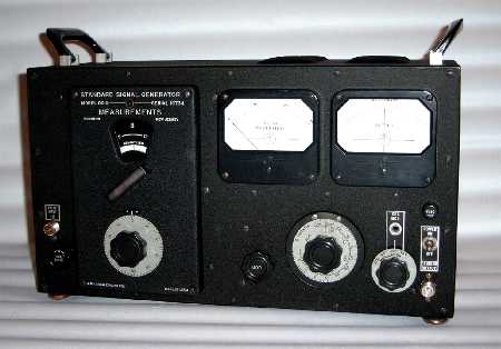
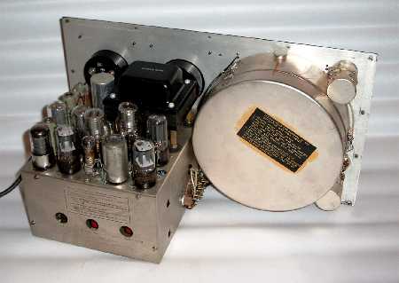
T1034 RF Signal Generator
Schematic
External photo
Internal photo
All our original source had was the pullout schematic - he's still looking for the
rest of the manual... If anybody has it, let us know.
The T-1034 RF generator is a relabeled Measurements Corp. Model 80 generator. The
original Model 80 (1944 vintage) ran from 2 MHz and went up to 400 MHz and were built
by various companies under military contract under the designation TS-497A and TS-497B.
The later 80-R model dropped the 2-5 MHz lowest frequency band and replaced it with a
new 400-475 MHz highest frequency band (the mechanical design limits the number of
frequency bands). The basic RF design relies on a 955 acorn triode connected as Colpitts
oscillator. The 955 tube sits in a round silvered can (visible in the internal photo)
surrounded by the various oscillator coils, which rotate into position with the band
switching knob. The mechanical internals are beautifully laid out and a fine piece of
precision work rivialling a good watch. Because the oscillator delivers the output power
too, modulation is limited to 30% and is AM only - but there is enough FM in the output
to be usable. The RF output power is induction coupled to a variable attenuator. The
80-R was built through the 1960s.
Technical Manual TM 11-5030A (3.9 MB) is for the
TS-497B/URR military version of the Model 80. There are enough differences that we'd
like to have the regular manual also. As far as military manuals go, if anyone has a
copy of the later TM 11-6625-253-12P we'd like to get a copy.
|
|
|
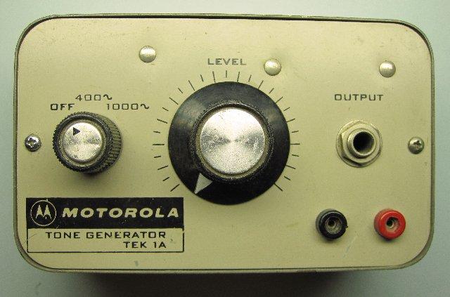
TEK-1A Tone Generator
Manual 522 kB PDF
Photo
This is a 2-tone test unit that was used to feed the external modulation port of an
RF generator. 6881101A91-B
An older manual can be found here
as a 687 kB PDF file. 6881101A91-O.
|
|
|
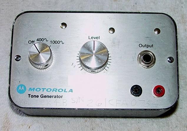
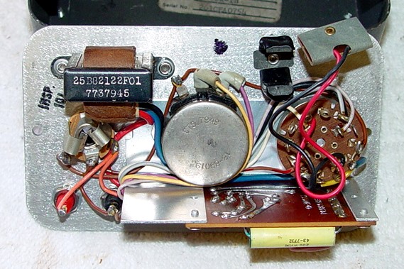
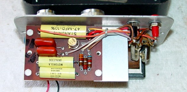
TEK-1B Tone Generator
Front Photo
Inside Photo #1
Inside Photo #2
This seems to be a later version of the TEK-1A tone generator.
|
|
|
TEK-7A Alignment Meter
Manual 165 kB PDF
This is essentially a mini-test-set plus an RF probe. 6881103A68-C
|
|
|
TEK-20 PL Tone Generator
Manual 215 kB PDF
Photo
This unit is similar to the TEK-1A tone generator above, but it accepts a single
Vibrasender reed and provides an adjustable output that could be used as necessary.
6881102A44-O.
|
|
|
TEK-21 Pulse Generator
Manual 244 kB PDF
Smaller file 175 kB PDF
This is a generator used in testing "Extender" equipped mobile radio receivers. An "extender"
is an IF-based noise blanker, usually found on 25-54 MHz radios but occasionally can be
found on 136-174 MHz equipment. Manual number is 6881102A42-O.
|

|
There's about 1.5GB of additional Motorola Test Equipment information, with some duplication,
that was sent to repeater-builder anonymously on a DVD. It's stored at our sister-site
that can be found here (Motorola Index #3).
|

|
The R20xx "B" and "C" models are almost identical, close enough that the "B" manual can
be used with a "C" model and vice versa. The "A" and "D" models are vastly different.
Things like the power supplies, front panel, and most of the circuit boards are used
in all models; the 20XX number merely determines what optional features are present.
For example, the R2021D is an R2001D equipped with the trunking option.
Most articles and manuals consider the R2001 to be the base / generic model number.
|
|
|
Turning the intensity down on your service monitor will definitely prevent burn-in of
data on the CRT phosphor screen, however everything else is still running, generating
heat, and aging. The CRT filament is heating the CRT cathode and emitting electrons.
Those elements have a limited life span and don't stop aging if you just turn the
intensity down. You're better off putting the unit into Standby (to charge the battery
and/or keep the ovenized high-stability reference oscillator hot) or shut it Off. Even
when off, there's still some small power being drawn, and lightning can still get in
through the power line, so unplugging the unit is really the safest way to go.
|
|
|
If you decide to remove the knobs and clean the front panel of your service monitor, you
should make a large paper drawing of the knob location first and put each knob, or pair of
knobs, in their respective locations on the drawing. Some of the concentric knobs have a
different hole size, and a little preparation beforehand will save you a lot of aggravation
when you put the knobs back. There are three concentric dual pots: Focus/Intensity, Vert/Horiz
Position, and Duplex Coarse/Fine Frequency. There are three concentric switches with pots:
Horizontal Range/Vernier, Vertical Range/Vernier, and Trigger Mode/Level. Also, some of the
larger knobs have two pointers on them, not just one. While you have the knobs off, clean
them in some hot soapy water and consider using something like Liquid Paper or White-Out or
other white correction fluid to re-paint the indicator lines on those knobs that have them.
|
|
|
R2000 series Differences 2.2 MB PDF by
Robert W. Meister WA1MIK
A list of major, and mostly visible, differences between the A, B, C, and D versions of these
popular CRT-based service monitors. Includes front and back photos from the various manuals.
People can change knobs and even model and serial number stickers, but the majority of the
features are solidly entrenched in each version. You ought to read this before buying a
used unit.
|
|
|
R2001 series Service Monitor Power Supply
Repairs by Steve Goggans K7LZJ
Steve goes through some personal experiences repairing the low-voltage and high-voltage
power supplies on these units, and provides additional useful repair hints and tips.
|
|
|
R2001 series Service Monitor Step Attenuator
Repairs by Steve Goggans K7LZJ
Steve continues his repair efforts with the step attenuator on one of his service monitors.
|
|
|
R2001 series Service Monitor Extender
Boards and Cables by Steve Goggans K7LZJ and Robert Meister WA1MIK
Sooner or later you'll need to extend a board or module. Motorola made an extender
kit a long time ago. This article shows you how to make your own cables and an extender
board that does the job.
|
|
|
Replacing the Power Supply Capacitors in the
R2001B and R2001C series Service Monitors by Robert Meister WA1MIK
The display (CRT) in my R2001B was extremely dim and everyone suggested replacing all of
the power supply capacitors. This article is an adjunct to Steve's article above. It also
has clean scans of the power supply sections of the R2001C manual.
|
|
|
Replacing the R2001B and R2001C Screw-terminal
Power Supply Capacitors by Robert Meister WA1MIK
I wasn't happy with the amount of ripple and noise on the two screw-terminal capacitors, and
since those caps in one of Steve's monitors had died, we decided to find suitable snap-in
replacements. Apparently my caps were just fine, but they are a ticking time-bomb.
|
|
|
Restoring the CRT on a Motorola R2001-series
Communications System Analyzer by Robert Meister WA1MIK
The display (CRT) in my R2001B was extremely dim even after replacing all of the power
supply capacitors. A CRT Analyzer and Rejuvenator got it working great again.
|
|
|
R20xxD series Service Monitor Power
Supply Repair by Steve Goggans K7LZJ and Robert Meister WA1MIK
A blown-up power supply was the next challenge, which included determining the value
of a couple of parts. Read all about it.
|
|
|
Replacing the RX Antenna Fuse on the
R20xxD series Service Monitors by Steve Goggans K7LZJ and Robert Meister WA1MIK
There's a very small 1/16A fuse inside the RX Antenna BNC jack. This article shows
what little space is available and suggests some replacement fuses.
|
|
|
R2001 series Service Monitor IEEE and
Cellbus Jumper Card Information by Steve Goggans K7LZJ and Robert Meister WA1MIK
Jumper cards are installed in service monitors that don't have IEEE or Cellbus cards. These
pass various signals through the otherwise empty motherboard sockets.
|
|
|
Is the fan on your R20xxB or C-series service monitor noisy or broken? A good replacement
is the AC Infinity Axial model HS9225A-X and is 92x92x25mm available from
here.
It comes with two finger guards, a 4ft AC cord, mounting screws, and a booklet, all in a nice
foam-lined box for about $18. Bob found the supplied screws were way too long so he used
some shorter #6-32 hardware instead. You only need one finger guard. He cut and spliced
the fan connector end of the AC cord onto the existing fan cord on his R2001B. Remember,
the fan blows air out of the rear of the service monitor. The D-series uses
the same dimension fan but it's 12VDC instead of 120VAC (see below). The A-series has no fan.
|
|
|
The R2001D units used a 12 volt DC fan. One was the Nidec "Beta SL Model TA-350". Jameco has the exact replacement fan
here.
|
|
|
The R20xx "B" and "C" models are almost identical, close enough that the "B" manual can
be used with a "C" model and vice versa. The "A" and "D" models are vastly different.
Things like the power supplies, front panel, and most of the circuit boards are used
in all models; the 20XX number merely determines what optional features are present.
Most articles and manuals consider the R2001 to be the base / generic model number.
|
|
|
Turning the intensity down on your service monitor will definitely prevent burn-in of
data on the CRT phosphor screen, however everything else is still running, generating
heat, and aging. The CRT filament is heating the CRT cathode and emitting electrons.
Those elements have a limited life span and don't stop aging if you just turn the
intensity down. You're better off putting the unit into Standby (to charge the battery
and/or keep the ovenized high-stability reference oscillator hot) or shut it Off. Even
when off, there's still some small power being drawn, and lightning can still get in
through the power line, so unplugging the unit is really the safest way to go.
|
|
|
R2001A / R2002A series
Service Monitor Service Manual 12.6 MB PDF
6881069A84-O dated 15-May-1980. This manual was professionally scanned in full-page mode.
The resulting file has been optimized, is searchable, and has bookmarks for each chapter.
IEEE-488 Option (GP-IB) commands can be found at the end of this file. These are
probably universal for most of the R20xx series.
|
|
|
R2001B / R2002B series
Service Monitor Service Manual 12.4 MB PDF
6881069A93-O dated 30-Jun-1981. This manual was professionally scanned in full-page mode.
The resulting file has been optimized, is searchable, and has bookmarks for each chapter.
Option RTP-1002A Battery Pack can be found at the end of this file. This is probably
universal for most of the R20xx series.
|
|
|
R2001C / R2002C series
Service Monitor Service Manual 12.5 MB PDF
6881069A99-O dated 01-Dec-1982 This manual was professionally scanned in full-page mode.
The resulting file has been optimized, is searchable, and has bookmarks for each chapter.
Option RTP-1002A Battery Pack and IEEE-488 Option (GP-IB) commands can be found at the
end of this file.can be found at the end of this file. These are probably universal
for most of the R20xx series.
|
|
|
R2001D Communications System Analyzer
Maintenance Manual - Complete 81.53 MB PDF
68P81069A63-0 dated 3/29/85
This entry is dedicated in memory of Robert W. Meister by KKC & JG
|
|
|
R2001D Communications System Analyzer
Operator's Manual 6 MB PDF
6881069A66-B dated 15-Jul-1985. This is a great manual to learn how to use your
R20xx-series!
|
|
|
Motorola R-2001D Communications System Analyzer Maintenance Manual
A dedicated page with individual PDF downloads of each section.
|
|
|
R2001D Communications System Analyzer
Service Manual 45 MB PDF
6881069A63-O dated 29-Mar-1985.
|
|
|
R2001D series Service Monitor Alignment
Procedures 4.7 MB PDF
Scanned and cleaned extract of just the alignment section (3) from the cleanest and latest
copy of the service manual available. The R2001 A/B/C alignment sections are listed above.
|
|
|
R2008C Communications System Analyzer
Operator's Manual 2.7 MB PDF
6881069A70-O dated 28-Jun-1984.
|
|
|
R20xx A/B/C series Service Monitor
Alignment Procedures 4 MB PDF
Scanned and cleaned extracts of just the alignment sections from depot service notes
and the appropriate service manuals. Note that there are errors, discrepancies, and
omissions in these pages. Don't blame me; I just assembled this PDF file from the
available information. The R2001D alignment section is listed separately below.
|
|
|
R20xxB series Service Monitor Adjustment
Procedures 101 kB PDF by Robert Meister WA1MIK
All of the adjustable components along with procedures developed by WA1MIK and K7LJZ
for those that were omitted from the alignment procedure section of the official manuals.
|
|
|
R20xxC series Service Monitor Adjustment
Procedures 102 kB PDF by Steve Goggans K7LJZ
All of the adjustable components along with procedures developed by WA1MIK and K7LJZ
for those that were omitted from the alignment procedure section of the official manuals.
|
|
|
R20xxD series Service Monitor Models
A short listing of R20xxD model numbers and the standard optional accessories. This
information may also apply to models with other suffix letters. The R2001 is the
base model; manuals with different last digits usually cover other configurations
and options. For example, the R2021D is an R2001D equipped with the trunking option.
|
|
|
R20xxD series Special Function Codes
A short listing of R20XXD special function codes. These were only available in the "D"
units.
|
|
|
R2008D / R2010D series Communications
System Analyzer Operator's Manual 3.5 MB PDF
6881069A62-O dated 08-Jul-1985. The R2008D is primarily a cellular telephone test
set. The R1010D is the UK version. This manual is a supplement to the R2001D manual.
|
|
|
R2200 / R2400
Communications Service Monitor Operator's Manual 2 MB PDF
6881069A79-B dated 15-Sept-1985. A much cleaner copy of the above manual can be found here:
R2200 / R2400
series Service Monitor Operator's Manual 3.6 MB PDF
|
|
|
R2200 / R2400 series Service
Monitor Maintenance Manual 50.6 MB PDF
6881069A76-O dated 12-Aug-1983. The above manual has been broken into small pieces:
- Part 1, 3.8 MB:
Table of Contents, Specs, Description, Operation, Maintenance, Troubleshooting,
Adjustment, Alignment, Calibration
- Part 2, 6.2 MB:
Calibration (cont.), Rear Panel (A01), Low Voltage Power Supply (A02), Scope Module (A03)
- Part 3, 6.7 MB:
Scope Module (cont.), Scope Amplifier Board (A04)
- Part 4, 2.6 MB:
Scope Amplifier Board (cont.), RF Synthesizer (A05)
- Part 5, 3.8 MB:
RF Synthesizer (cont.), Receiver Board (A06)
- Part 6, 5.4 MB:
Analog Interface Board (A07), Central Processing Unit Board (A08), Counter Board (A10)
- Part 7, 7.5 MB:
Counter Board (cont.), RF Module (A11)
- Part 8, 8.7 MB:
RF Module (cont.)
- Part 9, 5.7 MB:
Tone Synthesizer Board (A12), Reference/Audio Module (A13), Front Panel Interface Board (A14)
- Part 10, 5.9 MB:
Front Panel Interface Board (cont.), Front Panel Display Board (A15)
- Part 11, 6.6 MB:
Front Panel Display Board (cont.), Battery Pack (A16), Chassis Parts Breakdown, Main
Interconnect Board (A17, A18), Front Panel (A19), Accessories
|
|
|
R2550 Series Digital Communications System
Analyzer Operator's Manual 10 MB PDF
6880309E54 circa 1993. PDF'd and donated by Steve Goggans K7LZJ.
|
|
|
R26xx Digital Communications System Analyzer
Brochure 2.4MB PDF>
16 pages by General Dynamics on the R2600, R2625 and R2670.
|
|
|
R2600 Series Digital Communications
System Analyzer Operator's Manual 3.8 MB PDF
6880386B72 Rev 4, circa 1995. This covers the R-2600 series models.
|
|
|
R2600 Series Digital Communications
System Analyzer Maintenance Manual 29.5 MB PDF
RLN5237A Rev A, circa 2002; General Dynamics. This covers the R2600D, R2625B, R2660D, and
R2670B models. It also has appendices for the battery pack, FDMA option, and iDEN option.
|
|
|
R2670 Digital Communications System Analyzer
Description 580 kB PDF
12 pages of marketing.
|
|
|
R2670 Digital Communications System Analyzer
Operator's Manual 5.4 MB PDF
6880309F17 circa 1996. Scanned by Robert Meister WA1MIK. This covers the R-2600 series
models; the R-2670 has the FDMA options, which are listed below. This manual IS NOT text
serchable.
|
|
|
R2670/R2625 Series Digital Communications System Analyzer
Operator's Manual 3.17 MB PDF
This is the digital manual that General Dynamics shipped with their version of the unit around 2010 and
was provided by Mike Morris WA6ILQ. This is GD manual number CG-1089 Rev. A and IS text serchable.
|
|
|
R2670 Digital Communications System Analyzer
Analog Trunking Option Manual 2.3 MB PDF
Scanned by Colin Zapalac, shrunk by WA1MIK
|
|
|
R2670 Digital Communications System Analyzer
Astro Trunking Option Manual 1.1 MB PDF
Scanned by Colin Zapalac, shrunk by WA1MIK
|
|
|
R2670 Digital Communications System Analyzer
Astro Option Manual 2.0 MB PDF
Scanned by Colin Zapalac, shrunk by WA1MIK
|
|
|
R2670 Digital Communications System Analyzer
P25 Conventional Option Manual 2.0 MB PDF
Scanned by Colin Zapalac, shrunk by WA1MIK
|
|
|
R2670 Digital Communications System Analyzer
P25 Trunking Option Manual 466 kB PDF
Scanned by Colin Zapalac, shrunk by WA1MIK
|
|
|
R2670 Digital Communications System Analyzer
Securenet Option Manual 2.4 MB PDF
Scanned by Colin Zapalac, shrunk by WA1MIK
|
|
|
Colin Zapalac mentioned "Freedom CTE (branched from General Dynamics a few years ago)
acquired the equipment from Motorola to fully support the R2600-series Communications
System Analyzers. They can provide calibration, repair, and refurbishment and is
offering factory support and service contracts ($1200 annually, includes calibration)."
|
|
|
Farrell N3FS reported via email: "I just went through replacing the memory battery in an
R2670B service monitor. The original battery was a Plainview Batteries PMB 3.6B mounted
to the rear of the processor board. In the parts list from the service manual RLN-4120B,
this is BT1, p/n GG-6026385A001. Of course it is no longer available. It looks like a
cylinder about 1/2 inch tall and 7/8 inch diameter with 3 PC pins. A Varta 3V150H fits
perfectly. You can find these on the web. This battery has a 3-pin pc-board mount. The
original specs were 3.6 Volt, 140 mAH, Ni-MH. It mounts to the board perfectly. Changing
it and running the internal CAL procedure restored normal operation."
|
|
|
There's about 1.5GB of additional Motorola Service Monitor information, with some duplication,
that was sent to repeater-builder anonymously on a DVD. It's stored at our sister-site
that can be found here (Motorola Index #3).
|