Back to Home
and VX-6000 Radios
for Repeater Service
By John Haserick W1GPO
with Help from Bob WA1MIK

|
Back to Yaesu Back to Home |
Using the Vertex VX-5500 and VX-6000 Radios for Repeater Service By John Haserick W1GPO with Help from Bob WA1MIK |
|
Want a spectrally-clean 6-meter repeater transmitter with excellent audio, excellent shielding, frequency stability, deviation symmetry, SWR and over-temperature protection, and will do 120W continuous duty and no crystals to buy, and weighs only around 15 pounds?
This radio could be your answer. All that is required are two cooling fans, home made heat-sinking from aluminum angle stock, and a perforated aluminum replacement radio cover, with all aluminum and stainless hardware obtainable from Home Depot, plus two automotive-type noise suppressors (filters) to eliminate DC fan noise on the A+ line. There is absolutely no intra-cabinet desense when mated and duplexing with a Vertex Standard VX-5500L as a repeater receiver. One downside is it's not exactly good looking. Click on any photo for a larger view.

The VX-6000 is basically a VX-5500 with an additional 120W power amplifier (PA) and heat sink attached to the back of the radio. It uses the same accessories and software. The VX-6000 is capable of rear (trunk) mount and front (dash) mount configurations, although 15 pounds might be a bit much for today's plastic dashboards. The VX-5500 and VX-6000 series has models that cover VHF low-band, VHF high-band, or UHF.
Keeping It Cool:
The heat sinks are constructed from multiple pieces of aluminum angle stock that come in 4-foot lengths. Start with the largest, about 1-1/2" wide, 1/8" thick, and work down with the 1/16" thick stock to about 1/2" by 3/4" wide, 1/16" thick. We built the front with 1/8" thick stock with two top braces of 1/2" by 3/4" material to allow for possible through-hole rack panel fastening using a seven-inch high (4RU) rack panel. That never happened, so if it just rests on a flat surface as pictured, there was wasted heat-sinking that could have better been used on the rear of the radio. The existing M4 mounting screw holes were utilized on both sides of the radio. Choose your lengths carefully so you don't penetrate too far into the radio.

As pictured in the photo below, with the radio putting out about 135W for an hour with fans running, nothing on the external surface of the radio exceeded 100 degrees F. With the extra heat sinking, but no fans, the radio did get much hotter, so both are necessary for continuous duty (repeater) operation. We programmed the radio's time-out timer for three minutes.

The fan blowing upward, under the radio, is the CoolMaster from Marlin P. Jones Assoc. oval, about 8-9 inches or 200mm by 230mm by 30mm high, 12VDC, 0.40A, and runs very quietly. Other 200mm "Cooler Master" brand 700 RPM fans will also work. These are commonly sold as computer cabinet fans and often have colored LEDs used to illuminate them. The fan on the top is a standard 3-1/2 inch 12VDC square fan that also blows upward, taking heat out of the radio. It is located just above the two PA output transistors on the rear (high-power) PA deck of the radio. It is designed to pull air down through the adjacent top perforations in the gold anodized aluminum shield cover. The warmest part of the radio becomes the rear heat sink fins that the fan is not under, so ideally the bottom fan should have been located about 1-1/2 inches further back.
The original top cover is replaced with a gold anodized perforated cover made from one sheet folded back on itself, so there are two sheets perfectly lined up for extra strength. Anodized aluminum is non-conductive, so for proper shield grounding, stainless metric screws and stainless external lock washers that bite through the anodized surface were employed. Actually all screws are metric stainless steel that were purchased from Home Depot. The mike cord and rear Sub DB-25 Connector are internally RF-bypassed, so just the A+ and A- leads should have a couple of ferrites on each to insure that all undesirable RF energy stays inside the radio. Be very careful not to allow any metal particles to get inside the radio during construction. If something shorts out, the radio is probably not repairable. Here's the final photo of the transmitter radio and repeater controller.

Power System:
The power supply is a MeanWell 600 watt, 15V supply, turned down to 13.6V. These are probably similar to what they make for Duracomm, but this one is better because the cooling fan does not come on when the repeater is in standby mode, so there's only 20W of standby AC power draw and 330W when transmitting at 130W. There is over-voltage protection at slightly over 18V with this 15V model, so possibly the 12V model would have been a better choice, set at 13.6V, as the over-voltage protection would be lower. It was purchased from Jameco. There is also a 16,000uF 25V computer-grade capacitor across the power supply output terminals to provide additional filtering. Before we added that cap, the controller or the VX-6000 went into disable mode on the first day; it was reset by turning the VX6000 power switch off, then back on, and there's been no problem since.

The A+ filters (see the photo below for the brand and model number) are connected back to back with the blue leads connected between the filters.

6-meter Conversion:
The conversion to 6-meter operation is basically the same as for the VX-5500L mentioned in other articles. The harmonic filter coils are laid out differently than on the VX-5500L, but just spread the three harmonic filter coils on the rear PA board. The VX-5500L transmitter power drops off above around 53-53.5 MHz, and may also on the VX-6000L, but at 53.15 MHz the VX-6000L with no additional SVC-49 tuning put out about 135W. The programming cables are the same as with the VX-5500L. We used the SVC-49 software to reduce the transmitter output power to 120W, and we increased the deviation for best repeater use (flat, non-clipped audio), but if the radio is to be used as a base or mobile, the SVC-49 software is not needed.
Remember to disable the Noise Blanker on the receive radio.
Warren K2WD wrote a very nice article that describes the VCO tuning procedure. His article can be found on the Yaesu/Vertex/Standard index page.
Repeater Control:
For repeater service, a controller with fan control is ideal so the fan can be set to turn off about 15-30 seconds after transmission is finished, to flush out accumulating heat. We used a HamGadgets ID-O-Matic IV, with the RX Audio muting transistor Q5 removed, as it is not needed with the VX-5500L receiver. In fact, with Q5 installed, there was a terrible audio "thump" when the squelch closed, due to a DC voltage shift, that ruined the excellent, super quick, quiet squelch performance of the VX-5500, which rivals the famous MICOR squelch action. The aluminum enclosure for the ID-O-Matic is mounted to a bracket that sits on top of the transmit radio; it should have been larger. Note the cramped wiring that makes service difficult.

Joe K1IKE programmed the ID-O-Matic with a CW ID speed of 20 words per minute, 400 Hz tone, every 10 minutes, only when there is activity. COS is active-high, so if the receive radio loses power, it won't key the repeater. PTT is active-low. There is a one-second hang-time and a three-minute repeater timeout. Pin 4 is configured for fan control, active-low, and has a 30-second timeout. This drives a small relay inside the box that provides a ground for the fans. The controller keeps the fans going for 30 seconds after the repeater stops transmitting. The various ID-O-Matic connector signals are summarized in the table below.
| Pin | Signal Name |
|---|---|
| 1 | Ground |
| 2 | Power Input |
| 3 | PTT Output |
| 4 | CW Output / Fan Control |
| 7 | COR Input |
| 8 | Receiver Audio Input |
| 11 | Audio Output |
| 12 | Ground |
The various VX-5500 and VX-6000 accessory connector signals are summarized in the table below.
| Pin | Signal Name |
|---|---|
| 7 | Earth/Ground |
| 11 | External PTT (Input) |
| 13 | TXDI (Audio Input) |
| 14 | DC Out (SW B+) |
| 17 | RXDO (Audio Output) |
| 18 | Earth/Ground |
| 24 | Sp Mute (Output) |
| 25 | Earth/Ground |
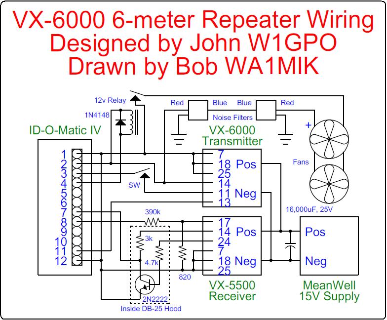
Here's how the ID-O-Matic is wired to the two radios. Connections are made using separate shielded multi-conductor cables from the DB-25 accessory connectors at the back of each radio. The ID-O-Matic is powered by the transmit radio (VX-6000). Click on the image to get a small PDF file.
Putting It All Together:
Here's a photo of the complete setup on the bench, ready to go. Note all the ferrite clip-on filters on the DC wires coming out of the power supply.

And here's a photo after installation into the rack cabinet. The 6-meter VX-5500L repeater transmitter is at the bottom, with its local mike connected, and the repeater controller is on top of the radio. Above it is the VX5500L repeater receiver and the MeanWell switching power supply with ferrites on the AC input cable, and above that is a Tripp-Lite filtered surge-protected power strip. There were no switching power supply noise problems using these extra precautions.

Credits and Acknowledgements:
Clarke N1PAH provided the repeater cabinet with special rack trays, the Tripp-Lite surge suppressor, the duplexer, etc. His callsign is on the repeater.
Joe K1IKE assembled and programmed the ID-O-Matic board. John installed the controller into its housing and added all DC and signal wiring for the repeater.
Bob WA1MIK drew the wiring diagram from information provided by John and Joe as well as the excellent ID-O-Matic documentation.
Contact Information:
John can be contacted at: jhaserick84 [ at ] comcast [ dot ] net.
Bob can be contacted at: his-callsign [ at ] comcast [ dot ] net.
Article text and photos by John Haserick W1GPO.
HTML coding and some text by Robert W. Meister WA1MIK.
Back to the top of the page
Back to Yaesu Index page
Back to Home
This web page created 09-Dec-2018
This web site, the information presented in and on its pages and in these modifications and conversions is © Copyrighted 1995 and (date of last update) by Kevin Custer W3KKC and multiple originating authors. All Rights Reserved, including that of paper and web publication elsewhere.