Back to Home
Vertex VX-5500/VX-6000
Low-band Repeater
By John Haserick W1GPO

|
Back to Yaesu Back to Home |
More Improvements to the Vertex VX-5500/VX-6000 Low-band Repeater By John Haserick W1GPO |
|
This version has a better controller, more refined cooling on the VX-6000L transmitter, and improved power line filtering on the VX-5500L receiver. The first version is still in service with its output set to 105W, but the receiver was changed to a Motorola Spectra-TAC (Micor) remote receiver for slightly better reception and better audio because it had double RF shielding and audio equalizing capability on the line audio output.
Click on any photo for a larger view. Some of the photos and diagrams are large.
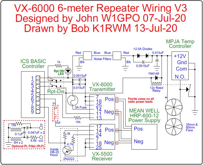
Let's start with an overall wiring diagram. Click on it to retrieve a PDF version.
Better Controllers:
The repeater controller is an ICS BASIC, which is very nice for a non-linked repeater, but as it's a single-port controller it will not handle linking. The controller operates a small reed relay that keys the transmitter PTT and grounds the A- to the 12VDC ball bearing fans. Two silicon diodes in series reduce the incoming 13.6VDC to 12VDC for the fans.
The fans are controlled by an intelligent heating/cooling relay (part number 32764MP) from MPJA.COM, set to go on at 92 degrees and off at 90 degrees, as measured on the inside of the rear heat sink. Temperature at this spot is kept to 30 degrees F above ambient room temperature by the fans. It is important to measure the temperature inside the PA, otherwise if the sensing bulb is outside the radio, the sensor gets cooled prematurely by the rear fan. Here is a picture of the sensor bulb and feed-through capacitor inside the rear of the PA compartment.

Note only one sensor lead to the temperature controller needs to go to the fan controller, as chassis ground is used as the other sensor lead. A feed-through cap replaced the external speaker jack, which was removed, insulated, and coiled up inside the radio, or it could be removed if the two center pins on the main board J2004 are jumpered to enable the front speaker.
Improved Cooling:
13.6VDC for the fans and controller (with a 3A mini blade fuse in series) is supplied by disconnecting the switched 13.6V from J2002 and placing a jumper to the 13.6V input screw terminal on the main board. I had to do this because the switched A+ source that normally feeds the Accessory jack is only rated at 250 mA. Power was taken from the Accessory jack to better filter RF out of the system. See the two photos below.

This photo also shows a black blob that's the rear speaker jack coiled up and inside some heat shrink tubing.

The rear fan (Delta EFC0812DB) blows towards the radio so air passes across the rear heat sink, bottom heat sink, and between the controller and the air inlet on top to provide fresh air to the air inlet screen that was added to the top cover of the radio. The DB-25 connector shell is solid metal to help transfer heat off the radio.

The air exits at the front of the radio.

The smaller fan on the top cover is placed above the ferrite output transformer, as it gets the hottest of the PA components, and blows the hot air up and out.

This fan is required for repeater operation. RF screening is also required for both the intake and fan openings on the top of the radio. Back to back (with blue leads tied together) automotive noise suppressors are required to keep the fan noise off the radio's A+ line. They are housed with the controller inside the aluminum box that sits over the top rear of the radio.

Here's a side view showing the radio with its mobile mounting bracket underneath. The fan controller is mounted to the bracket. The repeater controller box swings up and sits above the top rear of the radio, above the fan.

The BASIC controller's PTT output operates a relay and the transmit radio's PTT input. The relay makes the A- connection for the two fans. The temperature controller also makes the A- connection for the two fans, so they both turn on as soon as PTT is activated and they both stay on while the temperature is too high.
Improved Receiver Power Filtering and Audio:
I chose a VX-5500L as the receiver because of better inter-modulation rejection and narrower selectivity (modulation acceptance bandwidth of ± 7.6 KHz) than the VX-6000L receiver, probably because it was a later design with less gain in front of the mixer, but it still only needs 0.2µV for 12 dB SINAD. It should have a band-pass can between it and the duplexer for best performance. Like the VX-6000L with the same IF components, the overall IF response is a bullet shaped curve, therefore meant for analog, not digital voice. (Digital voice should have a flat topped, rounded corner IF response.)
RF shielding was improved with ferrites on the A+ and A- power leads, both inside and outside of the radio, in the form of six "mix 30" ferrites from Arrow Electronics ZCAT1325-0530A-BK (5mm) and ZCAT1730-0730A-BK (7mm), and one 13mm "mix 30" probably from DX Engineering. "Mix 30" is a little more effective on 6 meters than the usual "mix 43" ferrites.

RF filtering was also improved by using shielded audio cables and ferrites on the power cables of the transmit radio. Shielding extent was measured by transmitting 500mW to an isolated 50 ohm resistor attached to the Azden portable in the picture, and noting how far away from the radio it would receive the portable with a shielded dummy load on the receiver antenna connector. It turned out to be now almost as good shielding as with a stock Micor repeater with its front cabinet door off and a dummy load in its RX connector. The photo below shows the Azden portable next to the receiver.

The repeat audio was improved by changing the RX Audio Out to Flat Digital (not de-emphasized) by changing jumpers on the VX-5500 main board from JP2004 to JP2003, and adding the de-emphasis cap to the ICS controller. This eliminated the PL filtering and squelched audio from the VX-5500, which cut off too much low-frequency voice energy. The COS signal to the controller operates a very good audio mute circuit in the controller. The Vertex PL filter was replaced by a modified Micor PL filter for improved low frequency throughput, using the two 6 Henry chokes from the filter but different caps and resistors to customize to the Vertex radios. The schematic of this filter is shown in the overall wiring diagram at the top of this article.
The VX-5500L squelch is excellent and in fact rivals the classic Micor variable tail squelch. A 10K resistor was added between the audio output of the repeater controller and the audio input of the transmitter because of its high mike input sensitivity.
Contact Information:
John can be contacted at: jhaserick84 [ at ] comcast [ dot ] net.
Article text and photos by John Haserick W1GPO.
HTML coding and some text by Robert W. Meister WA1MIK.
Back to the top of the page
Back to Yaesu Index page
Back to Home
This web page created 06-Jul-2020
This web site, the information presented in and on its pages and in these modifications and conversions is © Copyrighted 1995 and (date of last update) by Kevin Custer W3KKC and multiple originating authors. All Rights Reserved, including that of paper and web publication elsewhere.