Back to Home
Conversion and Evaluation
By John Haserick W1GPO

|
Back to Yaesu Back to Home |
Vertex VX-5500L 6-Meter Conversion and Evaluation By John Haserick W1GPO |
|
Background:
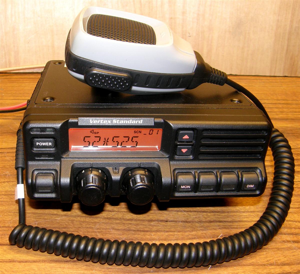
These radios cover the 29.7 to 37 MHz band (Version A) and the 37.0 to 50.0 MHz band (Version B). This article extends the Version B coverage up to 54 MHz. Both are capable of up to 70 watts on high power. Now that Motorola Solutions owns Vertex/Standard, more of these radios may be available on Ebay and other auction sites at a good discount. It remains to be seen how difficult it will now be to get replacement parts and accessories. Unlike Vertex/Standard, Motorola Solutions will not sell to an individual user, so parts will have to be obtained through an intermediate dealer, so try to get the radio with all accessories including the mounting bracket, but an excellent power cord can be easily constructed with some #12 stranded automotive wire, an in-line 15 Amp automotive fuse, and two insulated 0.250 female disconnects. Click on any photo for a larger view.
Accessing and Tuning the VCOs:
The conversion involves unsoldering the VCO shield, retuning the transmitter and upper half receiver VCO coils, spreading the turns on seven Power Amplifier (PA) and Harmonic Filter (HF) coils, and retuning the four receiver front-end coils.
By far the most challenging task is unsoldering the VCO shield without damaging the adjacent components. I used a 100W soldering iron and Solder Wick successfully on five radios. I found it helpful to hold the radio in a rubber padded holding vise with variable tilt. Re-soldering the shield was much easier, and did not require as much heat, especially if 60/40 lead solder is used, so a smaller iron works well.
[Note from WA1MIK: The receiver VCO has two sections: one covers 37.0-43.49 MHz, and the other covers 43.50-50.0 MHz. Only the higher section needs to be adjusted to cover the 6-meter band. You should program your radio with one channel that transmits and receives on 54.00 MHz. There are alignment tables and incomplete and confusing procedures in some of the VX-5500L Service Manuals; consult all of those manuals for the component and test-point locations while following the steps below.]
To adjust the transmitter VCO, place the radio on the highest frequency of 54 MHz, key the transmitter, and adjust T1006 so the VCO voltage, measured at TP1010, is 7.0 ± 0.1V. Then with the radio back in receive mode on the highest frequency of 54 MHz, adjust T1005 so the VCO voltage, measured at TP1010, is 7.0 ± 0.1V. There's no need to touch T1011, as that is used for receiving 43.49 MHz and below. I placed some Permaseal Blue RTV over the coil slugs to assure no movement in the future. Refer to this PDF file for the location of the VCO coils and test points.
The transmit frequency, actually the synthesizer's master reference oscillator, is adjusted with variable capacitor TC1001. Be certain the radio itself is at normal average operating temperature and adjust this cap so the transmit frequency is within ± 100 Hz. Refer to this PDF file for the location of the reference oscillator adjustment capacitor.
Warren K2WD wrote a very nice article that describes this procedure. His article can be found on the Yaesu/Vertex/Standard index page.
Tuning the Receiver:
The VX-5500 radios have a convenient IF metering point at pin 1 of the DSUB 25-pin accessory connector. This metering point is after the 450 kHz ceramic filter but before the limiter inside the IF IC. Feed a moderately weak signal at the center of the 6-meter frequencies to be received (such as 53 MHz) and peak the receiver's front-end coils T1001, T1002, T1003, and T1004. These are all located along the back edge of the main circuit board. There should be no noticeable degradation ± 1 MHz from this center-tuned 6M frequency.
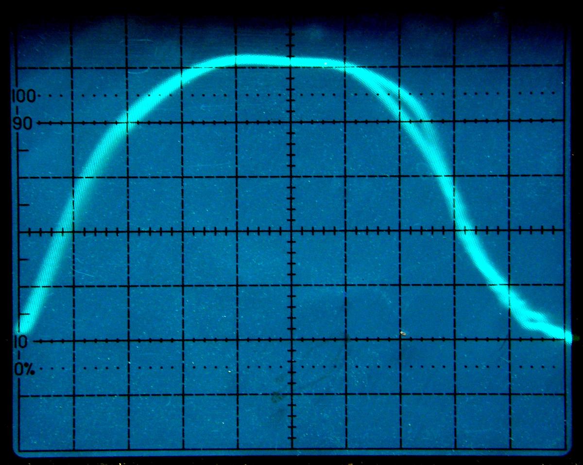
The double trace IF sweep above shows a good shape and only a minor discrepancy in the upper right corner where the forward and reverse sweeps diverge. In my opinion, this an optimum trace curve for voice, but not digital, as digital should have a wider flat top and more sharply rounded corners. The digital shape is not as good for voice as there is more noise volume heard between the speech sounds. The above double sweep trace is a composite of the 17.7 MHz crystal filters and the 450 kHz Murata ceramic filter. The Murata ceramic filter is not as precise as the monolithic crystal filters in say a GE Mastr II, where the response can often be made excellent by tweaking the adjacent IF coils, using the double trace sweep alignment method. However, the VX5500L modulation acceptance bandwidth is around ± 6.8 kHz, which perfectly handles 5 kHz deviation, and is about the same as with the GE Mastr II. The rear DB-25 connector and microphone connectors have good RF bypassing. The A+ and A- leads require ferrites, but then the radio is quite adequately shielded for duplexing. So the VX5500L does make a very good repeater receiver. It also excellent squelch action and CTCSS decoding. Compare this with the overly-wide modulation acceptance bandwidth of nearly ± 9 kHz on the Kenwood TK6110, Yaesu 8900R, and Alinco DR-06. If the modulation acceptance bandwidth is wider than the modulation received, then the receiver's unsquelched noise level is louder than the speech audio, reducing the range with noisy signals.
Tweaking the PA and HF:
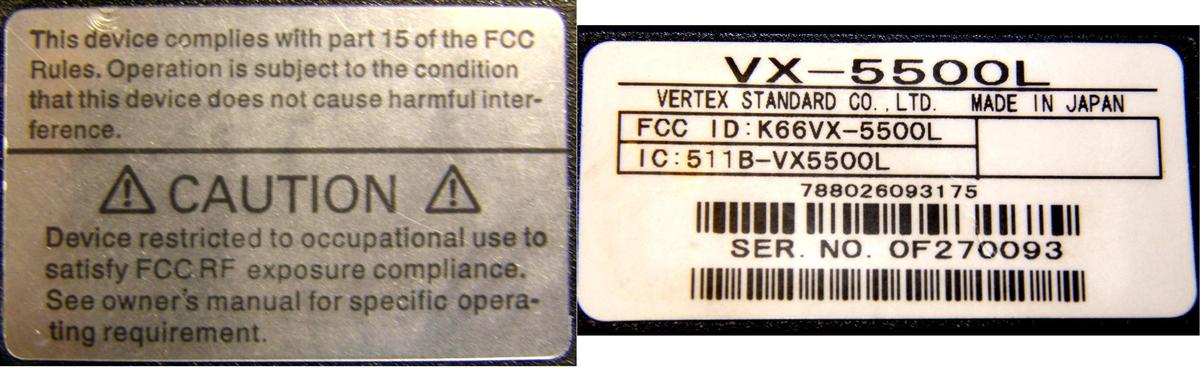
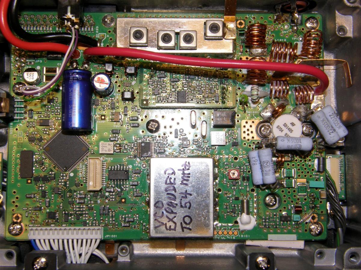
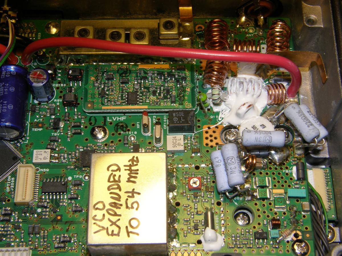
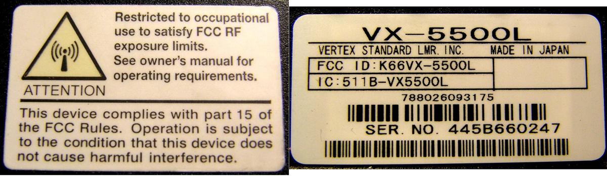
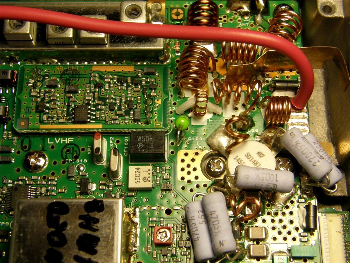
There are at least 2 versions of the transmitter PA circuitry (see the two "before modification" pictures). It appears that radios with a serial number containing a prefix of one digit and one letter before a suffix of six digits, and a warning label on the top cover with a silver/grey background, are the earlier version with most noticeably an SD1405 PA output transistor and Wakefield heat sink compound over L1025 and L1026, apparently to reduce excessive heat buildup in these coils without affecting coil performance. In the later version PA, L1026, L1014, and L1035 were replaced with coils of larger gauge wire, to eliminate the problem of coil overheating, so no heat sink compound was used on the coils in these radios. The compound, when removed, had no effect on the earlier version PA performance, other than some coils getting hotter than others. I did re-apply some Wakefield heat sink compound to both L1025 and L1026; this is visible in the "after tweaking" picture at the end of this section. I did not re-apply as much as was originally there, and that seemed to be effective enough at keeping the hottest coil temperatures (especially L1026) down, so all are the same temperature during transmissions. See the photos below.
Here's a photo showing the early version before tweaking the PA and HF coils.
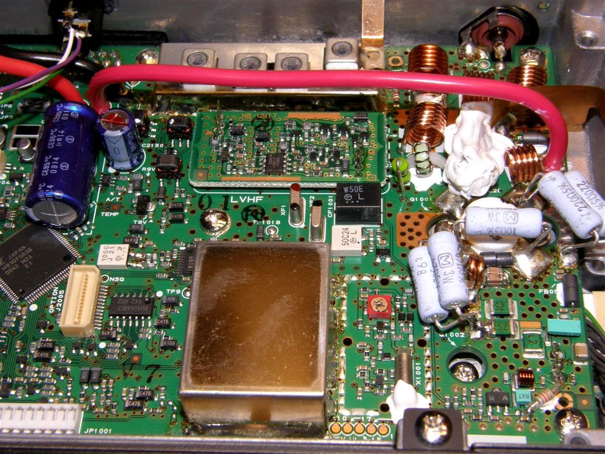
After removing the heat sink compound, you can see the coils much better.
The photo below shows the earlier version after tweaking the coils.
A more recent version apparently with serial numbers having a prefix of three digits and one letter before the suffix of six digits, and a warning label of mostly white background and a yellow background inside the triangle symbol, used an SD1487 PA output transistor and larger wire gauge on coils L1014, L1026, and L1035, so no heat sink compound was needed. There were also a few minor component changes around the base lead of the PA transistor. This newer version seems to run about 10% more efficiently on 6 meters. See the photos below.
Here's a photo showing the later version before tweaking the PA and HF coils.
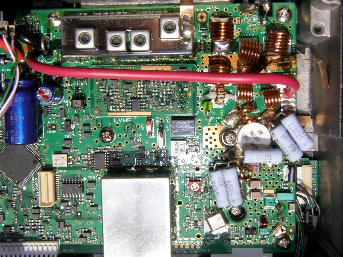
For both versions, L1011, L1017, and L1025 are spread to 13mm, and L1012 and L1014 are spread to 10mm. Try to spread the bottom turns almost as much as the top turns on all coils. Also for both versions, unsolder then remove 3/16 inch from L1026 on the PA transistor tab end then re-solder it, or alternatively spread L1026 as wide as possible (much easier and less risky). For the early version, L1026 and L1035 when pinched together will probably be optimum, whereas for the later version, spread these 1 1/2 turn coils about 9mm (see the two "after" pictures). L1032 was NOT spread by this procedure at all. Refer to this PDF file for the location of the PA and HF coils. The photo below shows the later version after tweaking the coils.
When spreading the coils, especially L1025 and L1026, highest efficiency (lowest current draw per watt output) is better for the PA than maximum output power.
Performance Results:
Here's the VX-5500L transmitter performance after conversion to 6 meters, with 13.3 volts DC measured at the radio, for both the early and later version radios.
| Early Version | Later Version | |||||
|---|---|---|---|---|---|---|
| Freq | Watts | Amps | Eff % | Watts | Amps | Eff % |
| 41.0 | 60.0 | 10.5 | 41.9 | 78.9 | 14.8 | 40.1 |
| 43.5 | 58.7 | 8.2 | 52.8 | 88.9 | 12.7 | 52.6 |
| 45.0 | 60.6 | 8.2 | 53.8 | 90.8 | 12.0 | 56.9 |
| 47.0 | 60.3 | 9.0 | 48.9 | 86.5 | 11.8 | 58.6 |
| 49.0 | 59.2 | 9.1 | 48.5 | 77.4 | 10.3 | 56.5 |
| 50.0 | 58.8 | 9.0 | 48.8 | 73.5 | 10.0 | 55.3 |
| 51.0 | 58.7 | 9.0 | 48.5 | 69.3 | 9.4 | 55.4 |
| 52.0 | 57.5 | 8.9 | 48.8 | 63.0 | 9.0 | 50.9 |
| 53.0 | 51.2 | 8.8 | 48.1 | 56.0 | 8.3 | 50.7 |
| 54.0 | 44.6 | 7.6 | 43.9 | 48.0 | 8.0 | 45.1 |
The radio should draw 8-9 amps at 13.3 volts while making about 55 watts on 6 meters, at least up to 53 MHz. The receive sensitivity is good up to 54 MHz.
Evaluation and Comments:
Unfortunately the CE-49 programming software (Version 5.13, 2012) will not let you adjust output power, receiver front-end varactor tuning, voice and CTCSS deviation, and a few other things; you need a separate alignment program and cable to change any of those parameters. On our two radios, factory deviation settings were good on 6 meters. Power output is a lot less on 54 MHz than at 51.5 MHz, probably due to the drive level changing to the PA output transistor, because the actual transmitter efficiency did not change that much. Even though the radio is rated for 70 watts output, we are getting around 55 watts on 6 meters, which is about right for the amount of heat buildup for this radio in amateur duty cycle. These radios also have high temperature power cutback as well as high SWR protection. Peak deviation increases from about ± 4.3 kHz to ± 4.8 kHz automatically on 6M, but the CTCSS deviation also increases to about ± 0.83 kHz, which could be the only reason to use the SVC-49 software, to bring the CTCSS down to about ± 0.63 kHz deviation.
A note of caution: DO NOT GROUND or even plug in or out the external speaker plug when there is power feeding the radio, as both sides of the external speaker jack are driven (one side is NOT grounded) and have about 6.6V DC on them, and a brief short is probably why we blew out the audio amplifier IC in one radio, even though the spec sheets claim it's short-circuit proof! An external 4-ohm speaker does wonders, as the built in tiny 8-ohm speaker is only rated at 1.5W.
For compatibility with most commercial radios, i.e. Motorola, set the Squelch Tail Elimination (reverse burst phase) to 120 degrees (in CE-49, click Common, Miscellaneous, CTCSS Tail Elim, then select 120 from the drop-down menu). CTCSS decode is rapid and very good.
There are quite a number of front panel button settings available, including High/Low transmitter power, Noise Blanker On/Off, multi-CTCSS, direct/repeater talk-around and many accessory connector options for linking to another radio, etc. With 250 channels divided into 20 groups the radio can be set up for different banks of frequencies for different mobile areas. Having a noise blanker on/off button within easy reach is also very useful to increase mobile range, as often with LED light noise at traffic intersections, receiver performance can be improved with the blanker turned off.
Alignment Software:
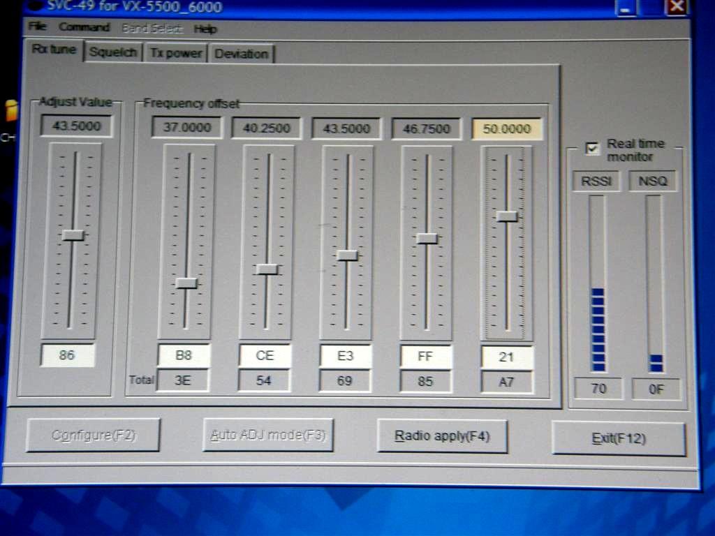
The CE-49 software and CT-71 programming cable are only used for programming channels, front panel buttons, and options, in other words, things the customer might see or want. Transmitter and receiver alignment must be done with SVC-49 software, which is specific to the VX-5500 and VX-6000, a CT-88 cable, an FIF-8 interface box, and a serial cable to your computer, none of which can be used with the CE-49 programming software. You will have to spend over $200 for the luxury of being able to adjust the receiver front end tuning and transmitter output power and deviation. Obviously this is not an ideal situation. Motorola Solutions, who took over Vertex Standard in 2018, has conveniently discontinued the low-band mobile radios.
UPDATE: June 2018: I purchased a package consisting of a special cable plus software to allow me to align the receiver, transmit power and transmit deviation on these radios. (This is currently available on Ebay for $39, including driver software.) The four receiver front-end slugs were peaked for 53 MHz before the radio was subjected to software alignment. The SVC-49 software does not operate above 50 MHz, so a change is made, then the radio results are checked on 6 meters, then back to the software for tweaking. Sometimes the radio does not revert back or loses the original code plug data, so the radio needs to go back through the CE-49 software and a separate computer cable to access the code plug data file previously stored in the computer. Therefore, first set up the radio frequencies, etc with the CE-49 software, SAVE THE DATA, then if High or Low power output, total deviation, or CTCSS deviation needs to be changed, then the SCV-49 software and interface cable that runs between the radio's rear DB25 and the computer's USB port is needed.I tried various combinations of sensitivity settings including all up full, however none but approximately the settings below, which are close to the factory settings, worked to allow the varactors to track both below and above 50 MHz, with about -118 dBm (0.28uV) for 20 dBQ (slight popping). In other words, unlike with at least the Kenwood TK6110, the firmware controlled varactor tracking does not stop and start over at 50 MHz, but continues to 54 MHz. Tweak the four front end coil slugs for best RSSI, on a fairly weak signal, using pin 1 at about 53 MHz, or wherever in the 6M band you desire peak sensitivity (or the center of the 6M frequencies you most desire, to gain perhaps 1-2 dB better sensitivity there without much degradation below 50 MHz).
Contact Information:
The author can be contacted for questions except programming, at: jhaserick84 [ at ] comcast [ dot ] net.
Article text and photos by John Haserick W1GPO.
HTML coding and some text by Robert W. Meister WA1MIK.
Back to the top of the page
Back to Yaesu Index page
Back to Home
This web page created 15-Jan-2018
This web site, the information presented in and on its pages and in these modifications and conversions is © Copyrighted 1995 and (date of last update) by Kevin Custer W3KKC and multiple originating authors. All Rights Reserved, including that of paper and web publication elsewhere.