Back to Home
UHF Repeater To Operate
in the 440-450 MHz Range
By Bryan Dygert KC8LMI

|
Up one level Back to Home |
Modifying a Vertex VXR-9000 UHF Repeater To Operate in the 440-450 MHz Range By Bryan Dygert KC8LMI |
|
I was helping a friend set up his first repeater, a Vertex VXR-9000 UHF (450-490MHz) model. I had already done the hex edit to the software and had it programmed. I was then faced with the issue of the RX VCO not locking up at his low input frequency of 441.150 MHz, well outside the design range of the repeater's receiver. After looking at the schematics, we decided to try and modify the VCO circuit to let it lock up at the lower frequencies. This involved taking the covers off the repeater and soldering a 2pF capacitor across the appropriate pads of the VCO. This, of course, voids any warranty. Perform this modification at your own risk!
Once the covers were removed, the challenge was gaining access to the VCO components. A square metal shield was well soldered continuously on all four sides, securely covering the components I needed to get to. This area is highly sensitive to any temperature changes, etc.
The first idea to remove the cover was heat. But my thinking was that it might damage the board and components if too much heat was applied. The thought of ruining a brand new repeater came to mind here! I then thought it might be better to very carefully cut the shield's top with a Dremel tool and cutoff wheel. The area surrounding the shield was carefully protected, so no debris or shavings could get into any other area of the repeater.
Click on any of the photos or images below for a larger view.
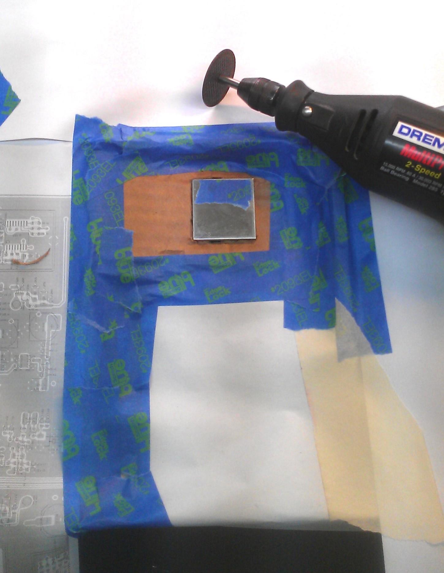
After very carefully cutting three sides of the top, I left one side intact. I was able to cut about half way thru to weaken it, and bend it up out of the way.
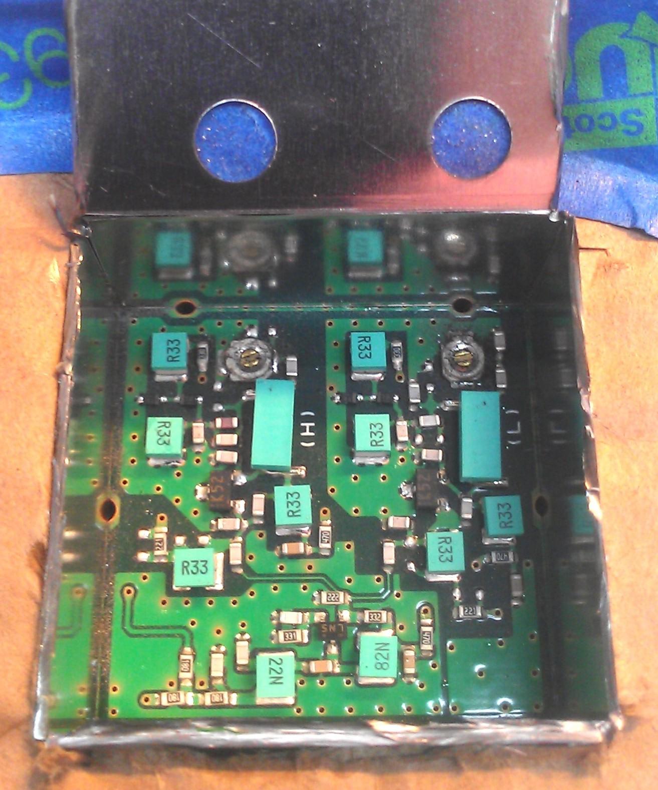
Once inside, I found the pads I needed to add the 2 pF cap. I didn't have an SMD part handy, so a leaded one was used, with short leads.
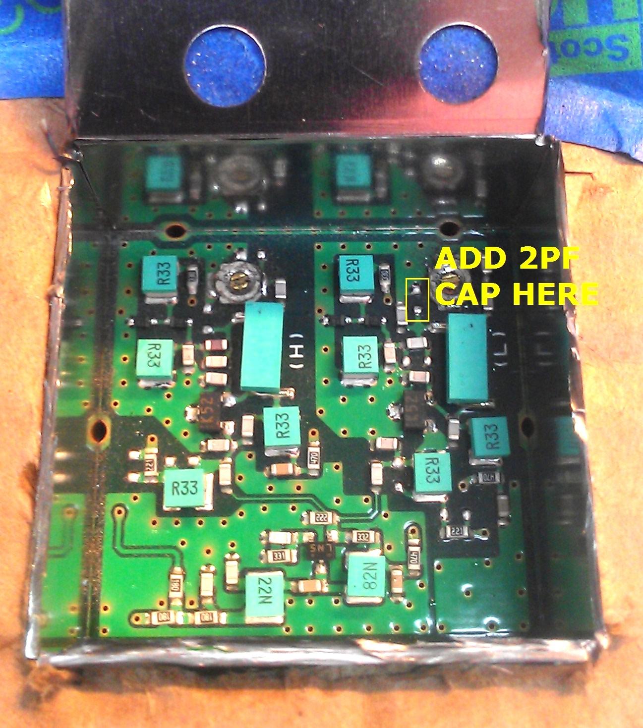
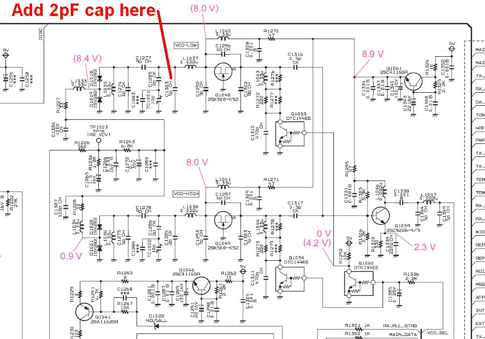
We're adding 2 pF where C1383 would be, next to TC1001, the RX VCO adjustment trimmer capacitor, as shown in the schematic below. Although C1383 is not listed as a part that varies with the operating range, this part was apparently not present in our station as the two pads were vacant.
The circuit board X-ray view in the service manual doesn't quite match the layout in the station, but it's close enough.
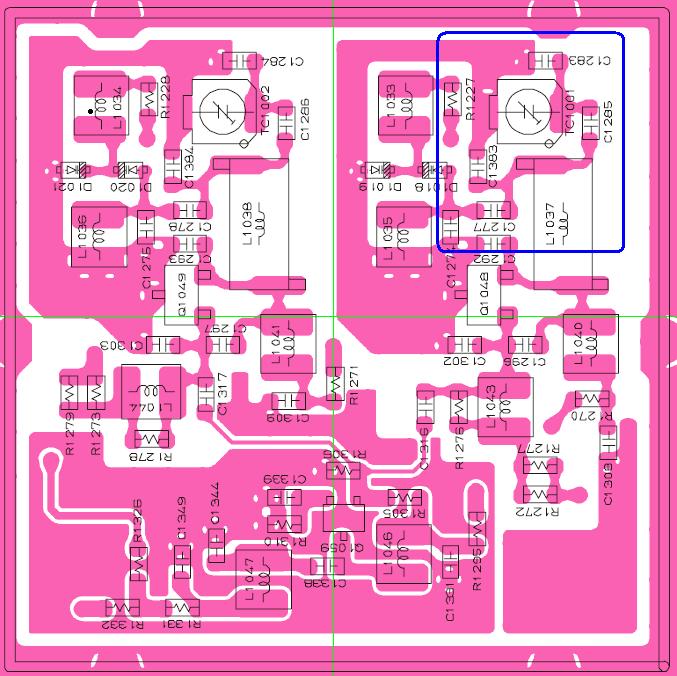
After soldering the cap in, the VCO tuned properly and its control voltage, at point "K", was about 1VDC, which is what it was at 450 MHz, and is now in the normal operating range and solidly locked on the new, lower receive frequency. Point "K" will rise with a higher VCO operating frequency.
I then used my old Wavetek 3100 service monitor and signal generator to better tune the RX band pass, using the software alignment values. After experimenting, I found that a setting of 60 worked for this station. Your results may vary.
My service monitor is old and hasn't been calibrated in a long time. I'm currently showing a sensitivity of 1.7uV to break squelch.
Contact Information:
The author can be contacted at: his-callsign [ at ] hotmail [ dot ] com.
Back to the top of the page
Up one level
Back to Home
This page originally created Wednesday 12-Mar-2014.
Article text © Copyright 2014 by Bryan Dygert KC8LMI.
Layout and HTML conversion © Copyright 2014 by Robert W. Meister WA1MIK.
This web page, this web site, the information presented in and on its pages and in these modifications and conversions is © Copyrighted 1995 and (date of last update) by Kevin Custer W3KKC and multiple originating authors. All Rights Reserved, including that of paper and web publication elsewhere.