Motorola index
Home page
Originally By Robert Meister WA1MIK (SK)
Currently Maintained by Mike Morris WA6ILQ

|
Maxtrac Index Motorola index Home page |
Motorola GM300 Family Information Page Originally By Robert Meister WA1MIK (SK) Currently Maintained by Mike Morris WA6ILQ |
|
CONTRIBUTIONS TO THIS PAGE ARE WELCOME!
Actually to any page at this web site! (even one that just points out a typo).
We are looking for a knowledgeable someone who could write an article that covers how to resolve any of the radio programming errors 51-58 (Radio Codeplug Error).
The GM300 family was Motorola's next step in the mobile product line after the MaxTrac / Radius radios. It includes the M10 single channel radio, the M120 and M130 two-channel radios, and the GM300 8-channel and 16 channel radios. The GM300 schematics are similar to the MaxTrac / Radius radios. You can even interchange some boards between the GM300 and MaxTrac / Radius radios. Like the MaxTrac, the GM300 line has been discontinued by Motorola.
Naturally, you need GM300 family programming software, but if you've ever programmed a MaxTrac, you'll be right at home with the GM300. The radios operate the same, the programming cable is the same. You will want to find the HVN8177F version R05.00.00 RSS which is dated December 1995 (the last / final version). See below for more info on the RSS and programming.
GM300 family mobile radios cover the VHF (136-174 MHz in two ranges) and UHF (403-520 MHz in four ranges) bands, with 8 or 16 channels, 12.5 or 20 / 25 / 30 KHz channel spacing, and 10, 25, and 35-45 watt power levels. They use the same accessories (loudspeakers, microphones, accessory plugs, power cords, mounting brackets, etc.) as the MaxTracs.
The GM300 family is built similarly to a MaxTrac / Radius radio in that it has a radio board and a control board (which also has some audio circuitry on it). That control and audio board is frequently referred to as the logic board. However there are two different logic boards in the GM300 family of radios, both of which have a 16-pin accessory connector. The basic board is a two layer board and is called the "masked" logic board becuase the firmware was part of the mask that was used as the soldered-in microprocessor chip was made. It is used in the M10, M120 and the lower channel count GM300s. The microprocessor chip used on the masked board also has limited code plug space, hence fewer channels. The masked logic board has less capabilities, and the accessory socket has no programmable pins. Pin 14 can have either of two functions, and that selection is made with a jumper (JU809).
The "expanded" logic board (called this because it has four signal layers)
uses a different microprocessor chip with the control program (firmware) in a socketed EPROM,
and an external non-volatile RAM memory chip. It is easily identified at first look by the metal
shield over the microprocessor components. This board gives you the ability to program
several of the accessory jack pins and also gives you several signaling systems, such as
MDC1200. It is required if you plan on programming any of the accessory socket pins,
including using the "channel steering feature.
The expanded logic board is used only in the 2-channel M130 radio and the 16-channel GM300.
People have hex-edited the RSS to get 16 channels from masked logic board radios and
40 channels from the expanded logic board radios.
Note to eBay buyers: All GM300 control boards have a 16-pin accessory connector.
A "16-channel" GM300 could be a legitimate 16-channel radio with the
expanded logic board, or it could be a 8-channel that has the masked board and
been programmed with the modified RSS. The accessory socket on a GM300 that has the
masked logic board has no programmable pins. Always ask before sending money.
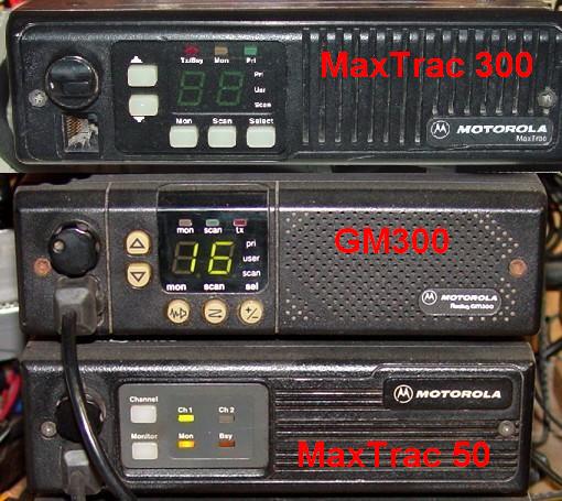
Here's a front view photo of a 16-channel MaxTrac, a 16-channel GM300, and a 2-channel MaxTrac: This photo is courtesy of David Malicki N1OFJ.
GM300 Model Numbers:
The first six characters are pretty much standard Motorola convention. The IF frequency is usually 45.1 MHz but if you have multiple radios near each other, this can cause interference, so you could order the radio with the 45.3 MHz alternate IF frequency.
| Mount | Power Watts | Band MHz | Series | I.F. MHz |
|---|---|---|---|---|
| M: front mount | 0: 1-10 | 3: 136-174 | GM | C: 45.1 |
| 3: 10-25 | 4: 403-520 | XQ | R: 45.3 | |
| 4: 25-45 | XV |
The XV-series are single channel radios. The XQ-series seems to be all two channel radios. The GM-series can be 8 or 16 channel radios. The XV and XQ may be used by the M10, M120, and M130 radios. The "GMR" (45.3 MHz IF Frequency) radios are rather rare.
The second six characters provide a lot of useful information about the capabilities of the radio and the boards contained within it.
| Spacing KHz | # Ch. | Logic Board | Range MHz | Rev. |
|---|---|---|---|---|
| 0: 12.5 | 0: 8 | C: Expanded | 1: 136-162 | A_ |
| 2: 20 / 25 / 30 | 9: 16 | D: Masked | 1: 403-430 | |
| 2: 146-174 | ||||
| 3: 438-470 | ||||
| 4: 465-490 | ||||
| 5: 490-520 |
A typical model number would be M44GMC09C3A_. This is a 40 watt, UHF radio, 45.1 MHz IF, narrow spacing (12.5 KHz), 16 channels, expanded logic board, 438-470 MHz range, sometimes referred to as a "Range 3" radio.
The GM300 was the first product line where the model number includes the specific frequency range the radio is capable of handling (10th character). You don't get that lucky with MaxTracs, Spectras, etc. It is NOT practical to change the frequency range for which the radio was manufactured. The RF board and PA assembly are frequency-dependent; the logic board and front panel are not. As the model number tells you which range the radio is, if you end up with the wrong one (assuming the radio hasn't been thrown together out of spare parts or had modules swapped) it's your own fault for not doing your homework.
It would appear that stock GM300s are not capable of any form of trunking operation. However they can do G-Star signaling for use with GE radio systems. Scholer-Johnson licensed the GM300 firmware and produced replacement firmware chips (only for the expanded control board GM300 and M130) that implemented the LTR analog trunking protocol.
This article is oriented towards the radios with "GMC" or "GMR" in the model number.
Specifications:
Click on the image to enlarge it.
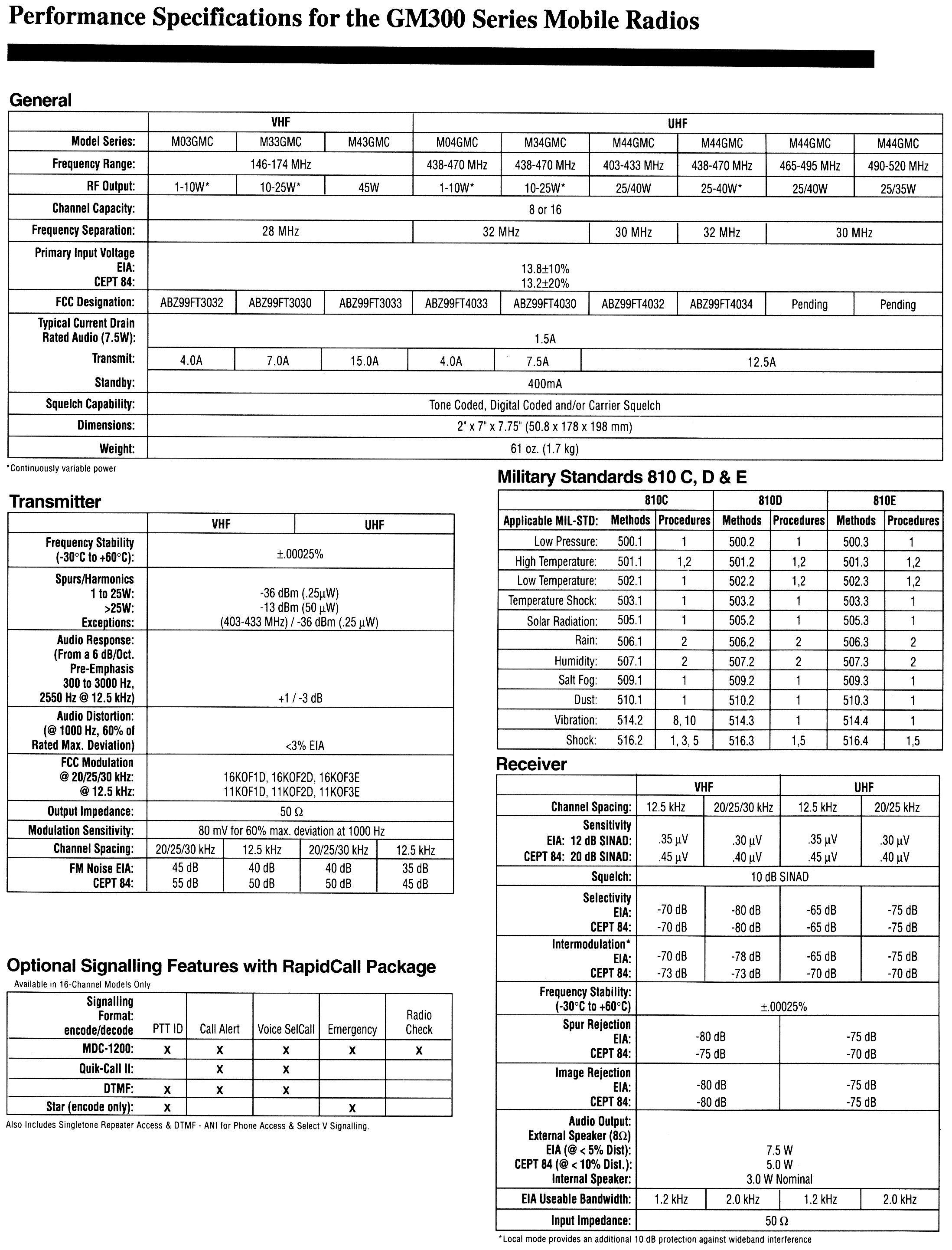
Note that the original service manual lists only VHF range 2, 146-174 MHz. A revision to the service manual adds Range 1, 136-162 MHz and updates the Range 2 circuit boards. Also, the power levels are continuously variable throughout the three ranges: 1-10, 10-25, 25-45 Watts. Running the RF power lower than the lower level of the specification is NOT recommended (i.e. running a 25-45 Watt radio at 5 watts). An under-driven PA deck is very inefficient and the excess power is turned into heat.
Board Numbers:
This list is sorted alphabetically by Function, then Description.
| Board # | Function | Description |
|---|---|---|
| HLN8075A | Display Board | |
| HLN8070A | Logic Board | Expanded, 4-layer |
| HLN8070D | Logic Board | Expanded, 4-layer |
| HLN8074A | Logic Board | Masked, 2-layer |
| HLN8074E | Logic Board | Masked, 2-layer |
| HLE8385A | UHF Power Amp | 403-433 MHz, 01-10 Watts |
| HLE8275A | UHF Power Amp | 403-433 MHz, 25-45 Watts |
| HLE8267A | UHF Power Amp | 438-470 MHz, 01-10 Watts |
| HLE8034A | UHF Power Amp | 438-470 MHz, 10-25 Watts |
| HLE8271A | UHF Power Amp | 438-470 MHz, 25-40 Watts |
| HLE8284A | UHF Power Amp | 465-495 MHz, 25-40 Watts |
| HLE8269A | UHF Power Amp | 490-520 MHz, 25-35 Watts |
| HLE8229A | UHF RF Board | 403-433 MHz, 25 KHz |
| HLE8230A | UHF RF Board | 403-433 MHz, 12.5 KHz |
| HLE8301A | UHF RF Board | 438-470 MHz, 12.5 KHz |
| HLE8300A | UHF RF Board | 438-470 MHz, 25 KHz |
| HLE8264A | UHF RF Board | 465-490 MHz, 12.5 KHz |
| HLE8263A | UHF RF Board | 465-490 MHz, 25 KHz |
| HLE8228A | UHF RF Board | 490-520 MHz, 12.5 KHz |
| HLE8227A | UHF RF Board | 490-520 MHz, 25 KHz |
| HLD8293A | VHF Power Amp | 136-162 MHz, 10-25 Watts |
| HLD8299A | VHF Power Amp | 146-174 MHz, 01-10 Watts |
| HLD8033A | VHF Power Amp | 146-174 MHz, 10-25 Watts |
| HLD8287A | VHF Power Amp | 146-174 MHz, 25-45 Watts |
| HLD8266A | VHF RF Board | 136-162 MHz, 12.5 KHz |
| HLD8265A | VHF RF Board | 136-162 MHz, 25 KHz |
| HLD8029A | VHF RF Board | 146-174 MHz, 12.5 KHz |
| HLD8031A | VHF RF Board | 146-174 MHz, 25 KHz |
| HLN8071A | Vol/Mic Board |
Logic Board Jumpers:
Click on any image to enlarge it.
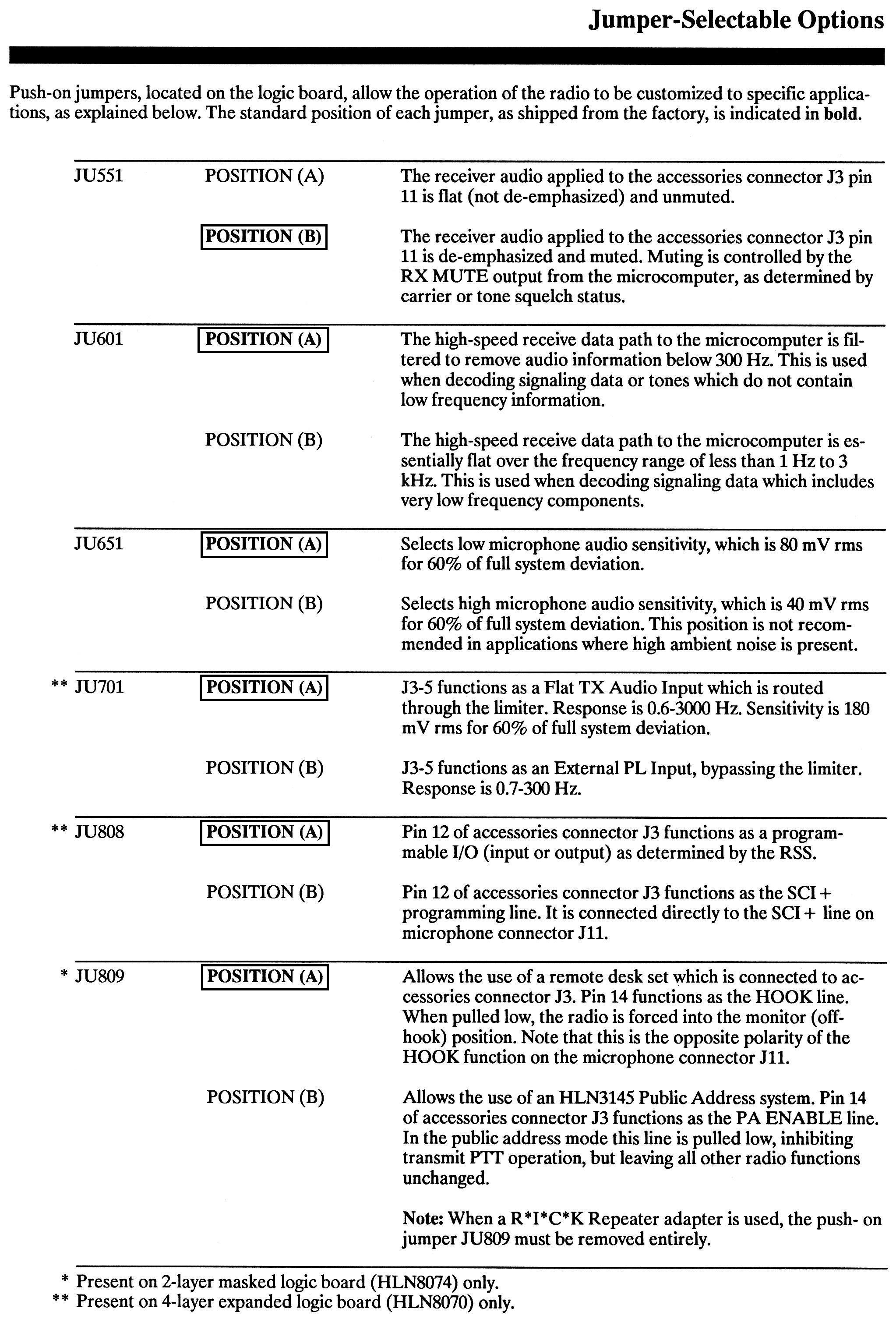
The documentation page above lists the jumpers as JUnnn. For some reason these are shown on the board layouts as either Pnnn or JUnnn. They're the same thing. There may or may not be silk-screened legend on the boards; it depends on the revision level.
There are two quite different logic boards used with the GM300. One (the expanded logic board) has a shield over the microprocessor components, its program is stored in a socketed EPROM, the board has four layers and the accessory socket has programmable pins, while the other (the less capable masked logic board) has all the components exposed, its program is stored within the microprocessor chip itself, the board only has two layers and the accessory socket has no programmable pins. The image below shows the location of the jumpers on the two-layer (masked) board:
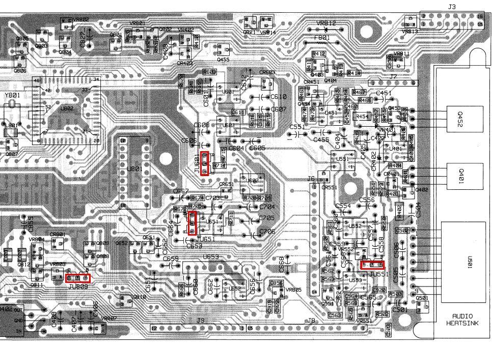
The image below shows the location of the jumpers on the four-layer (expanded) board.
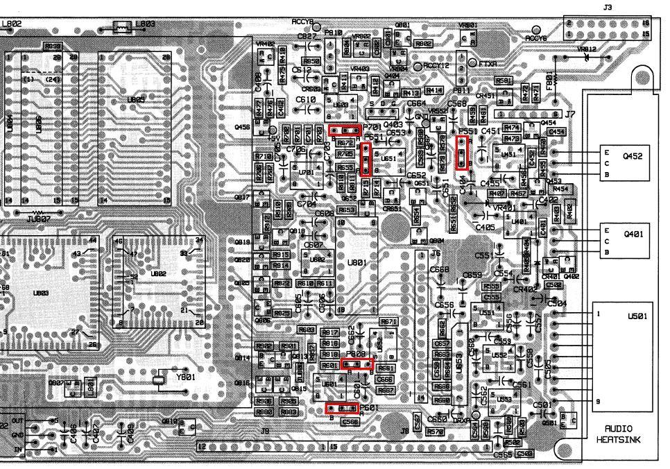
These jumpers are quite visible on the photo of the expanded GM300 logic board below. Note that some of them are also present on MaxTracs and have the same functions.
Accessory Connector:
Click on the image to enlarge it.
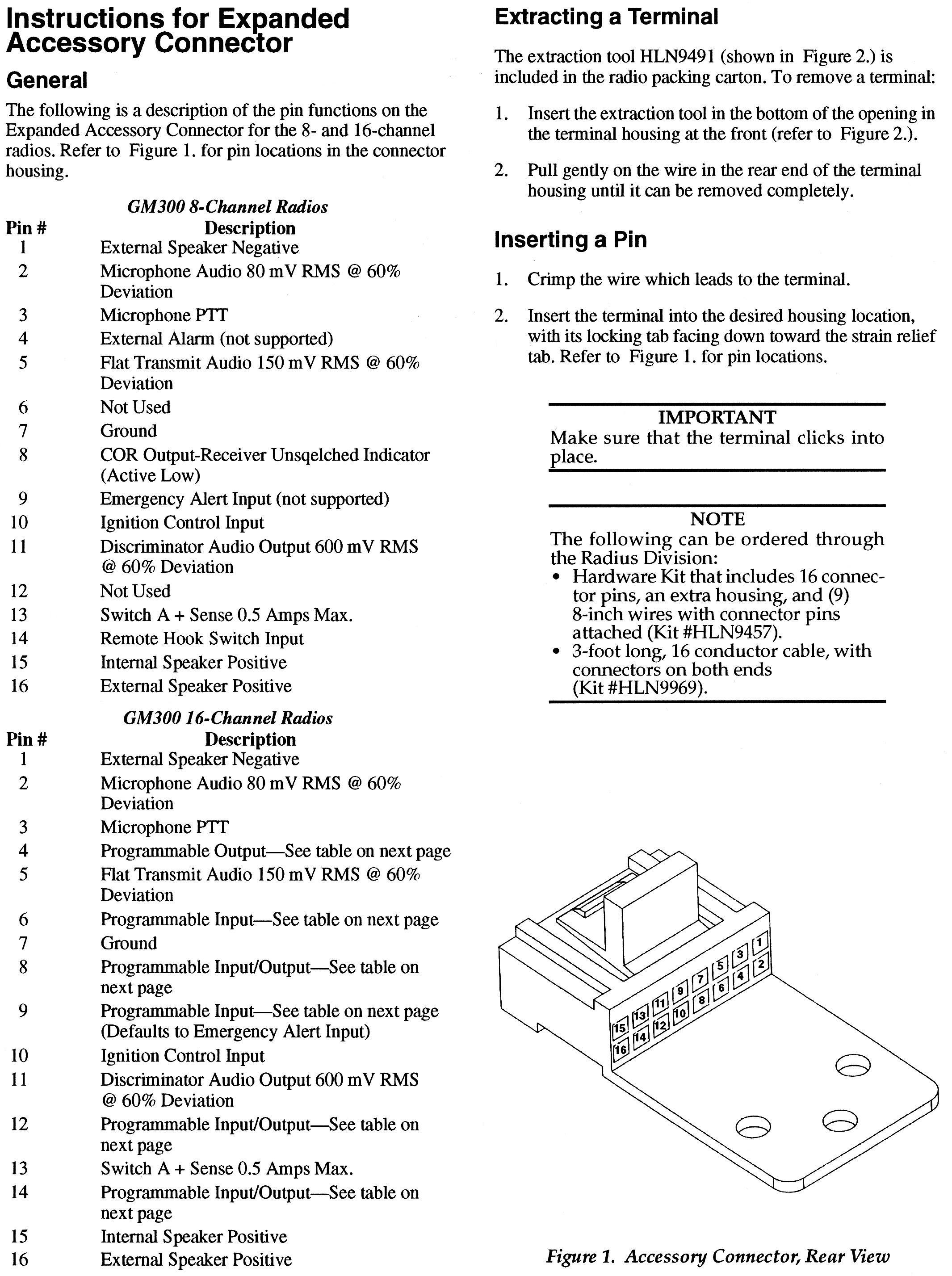
Note that the 8-channel radio signals are slightly different than the 16-channel radio signals. That may be due to the masked vs. expanded logic board. Fortunately, you can use an accessory plug wired for a MaxTrac (7-9, 15-16) in a GM300.
Click on the image to enlarge it.
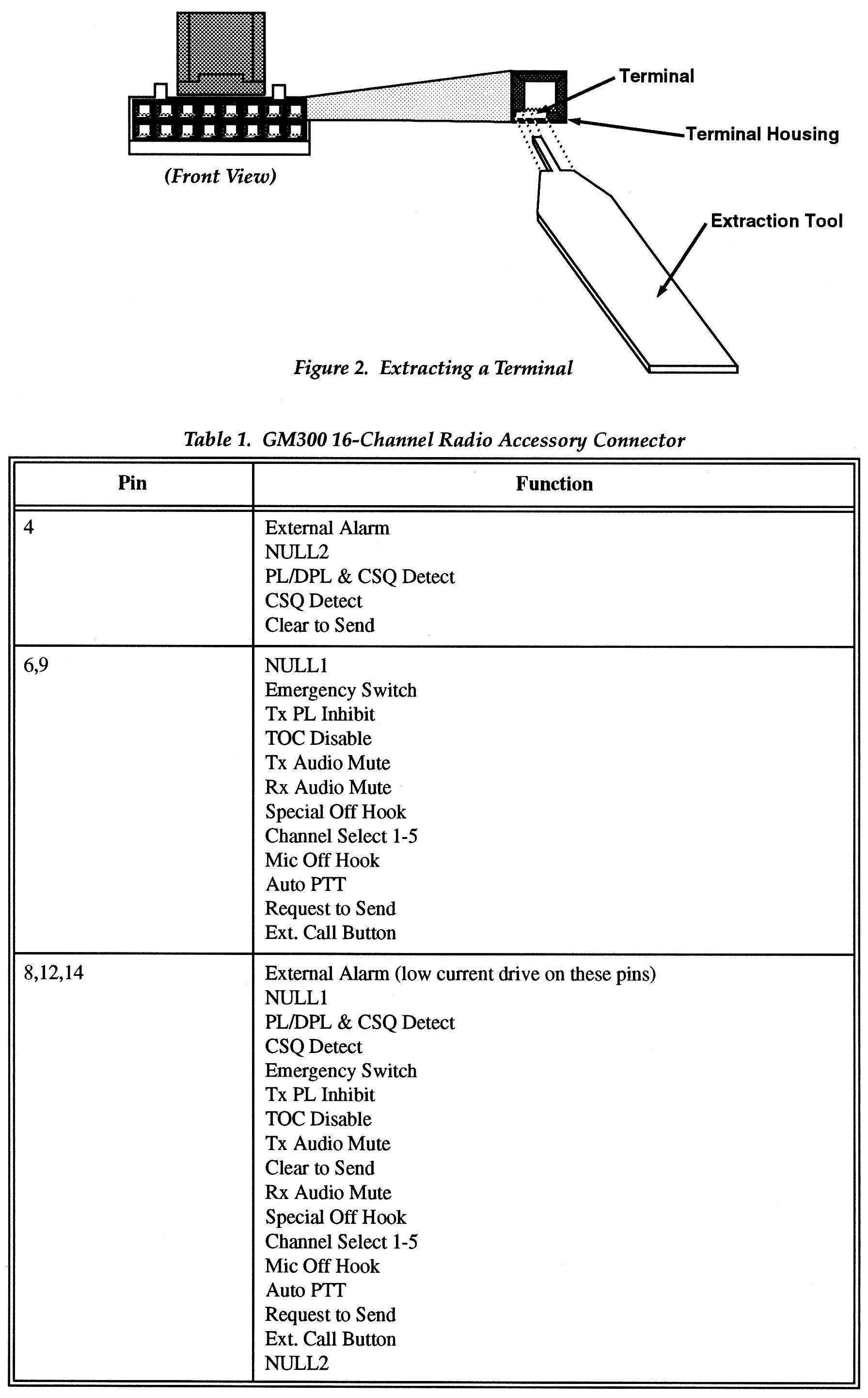
The accessory connector and pins are also well documented in the MaxTrac section.
Note that many accessory pins on the expanded (four-layer) logic board are programmable, whereas you're stuck with the pin assignments on the masked (two-layer) logic board and these can't be modified.
Channel Steering:
The Motorola Radius programming software only provides for three Channel Select input lines, not five like the expanded logic board GM300s.
The expanded logic board radios support "channel steering" through the accessory connector. You need to program the general-purpose I/O pins (6, 8, 9, 12, and 14) for "Channel Select". They turn into a binary coded input that allows you to select any of the possible 16 channels by grounding the appropriate input lines (assuming you've programmed the radio for active-low inputs). To select channel 1, ground the "Channel Select 1" line. Channels 1, 2, 4, 8, or 16 may be selected by grounding select line 1, 2, 3, 4, or 5 respectively. All other channels are selected by grounding multiple select lines. If you release all of these lines, the radio reverts to the channel selected by the front panel. If you select a channel that does not exist (i.e. 10 channels programmed and you select channel 15), the radio reverts to the channel selected by the front panel. Channel steering DOES work as expected on radios with more than 16 channels, i.e. you can select anything up to channel 31, as that's all that's possible with five select lines. This article tells you how to use channel steering.
Pins 4, 8, 12, 14 can be configured for COR. You can also add a resistor, a transistor and bring out COR on a separate wire (see the Maxtrac page). Pins 6, 8, 9, 12, 14 can be configured for Channel Select. So you can put COR on pin 4 and CS on the others. The preference for COR on pin 8 is due to the Maxtracs and masked (8-channel) GM300 radios have COR on pin 8 and that cannot be changed. If you want multiple features activated then COR has to be moved. It's up to the user to choose the desired functionality given the limited number (six) of programmable I/O lines.
Programming:
The HVN8177 programming software (RSS) programs the M10, M120, M130, and GM300 mobiles, as well as the GR300, GR400, and GR500 desktop repeaters (the ones that contained M10, M120, M130, or GM300 radios). The narrowbanded GR400s and GR500s could have narrowband radios or they could have an R1225 repeater module which is covered on a different page at this web site. Early versions of the HVN8177 RSS only supported COM1 and COM2, later versions added support for COM3 and COM4. Version 4.x.x and later supported the GMR series of radios. You want to find the final revision of HVN8177F R05.00.00 dated December 1995. The RSS is shipped on 3.5-inch diskettes and is an MS-DOS-only program.
The microphone connector is exactly the same as on a MaxTrac, and it's also well-documented in the MaxTrac section. The programming cable and RIB setup is the same as what you'd use for a MaxTrac or GTX.
You can hex-edit the Model Definition File (MDF) file in the RSS to allow an 8-channel radio to take 16 channels. Additional information is available at Colin Lowe's web site. You can also modify the MDF to allow a 16 channel radio (i.e. one with the expanded logic board) to accept 40 channels.
The M130 and the GM300 (both of which have the expanded logic board) support the same common signaling modes as a MaxTrac (PL, DPL, MDC, etc.) and the accessory socket has programmable pins.
Several people report that the RSS works OK running in DOSbox or DOSbox-X, when the emulated CPU is run at an emulated speed index of 190 to 400 (faster host machines may need lower indexes). Running in an emulator allows the use of USB-based programming cables, just make sure that they are mapped in the emulator to COM1 or COM2 and 8N1.
There is a software package called Radio Doctor. It was written in Visual Basic in the Windows 2000 / XP days by a hobbyist and allowed reading, updating and writing the frequencies in the GM300 codeplug. I heard second hand that the legal department of Motorola made the hobbyists life miserable and the program was abandoned "due to threats". If the creator of the program reads this I'd like to hear the full story. I've only seen version 1.3.0 and it is buggy and does not have the ability to program the accessory port. It only understands COM 1 or COM 2. It does allow programming 144-145 MHz frequencies in 146-174 MHz radios. Hacked codeplugs (like 16 channels in an 8 channel radio, or 24 in a 16 channel radio) will have problems. But it does work under XP, Win7-32, Win8-32, and Win10-32, and does allow editing frequency and tone information in the radios. It might work on 64-bit windows, I've not tried.
Radio Doctor will allow recovery of a radio that has an Error 58 in the codeplug. Download the radio, it will announce the Error, and allow you to go past it. Then change one little soft adjustment (write down the original value), like the Reference Oscillator Warp. Let Radio Doctor re-calculate the checksum, then write it back to the radio, then DO IT AGAIN and reset the Warp back to the original setting. Your radio with the Error 58 is now well again.
Ignition Control or Ignition Sense:
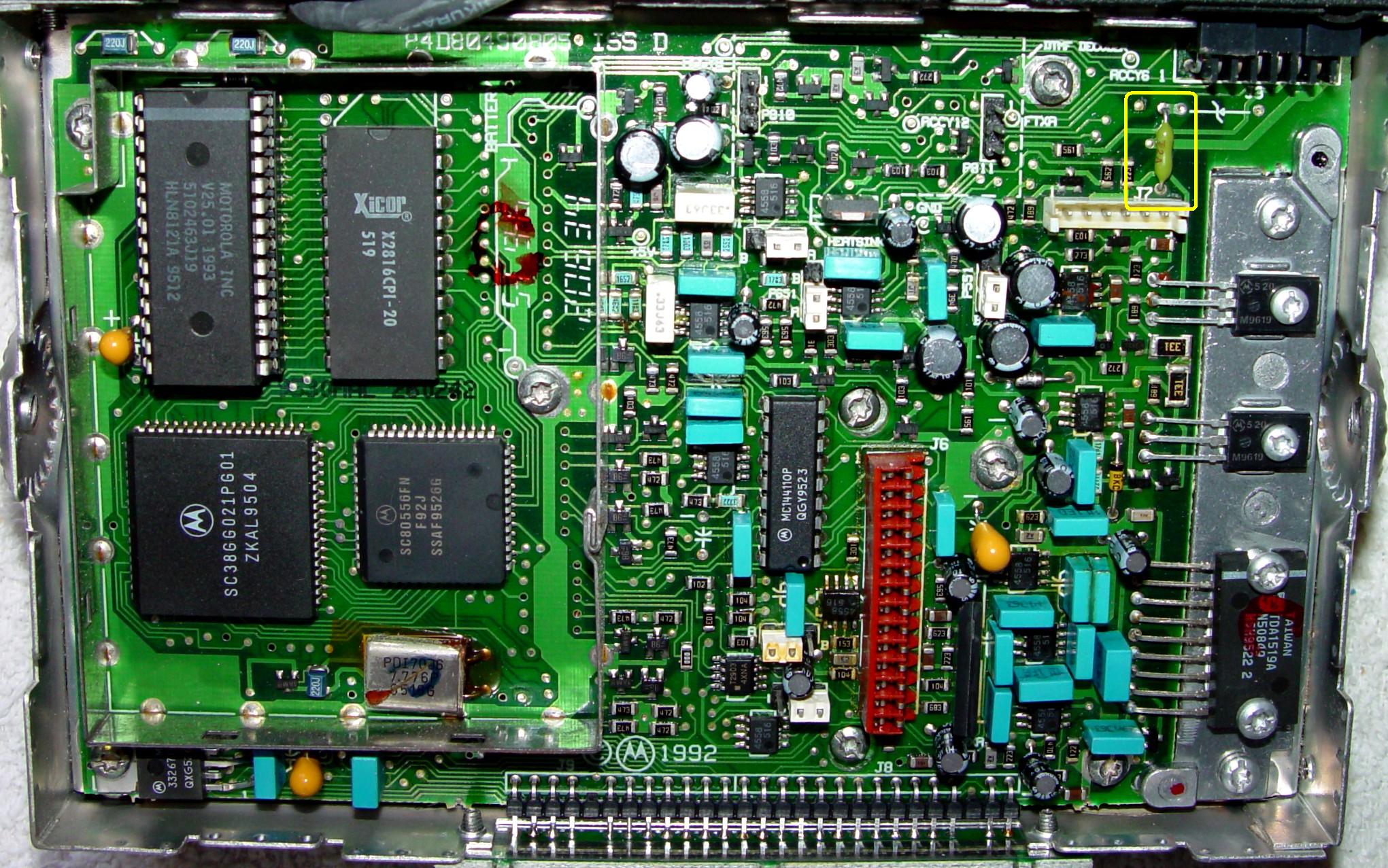
Like the MaxTrac, the GM300 radios also have optional Ignition Control or Ignition Sense via the Accessory connector. This 12 volt (nominal) signal runs through a fuse (F801) on the logic board. Its location depends on whether you have a masked logic board or an enhanced logic board. If you don't want this feature you will need to install a new fuse, a solid wire jumper (note recommended), or a 1-10 ohm 1/4w resistor in its place. For either board, the fuse/jumper is located near the Accessory connector and is outlined with a yellow box in the photos below.
This fuse supplies 12 volts to the Ignition Control pin of the Accessory connector. If 12 volts is present on that pin, the radio will turn on via the front-panel power switch. If this fuse is blown or removed, you must supply your own 12 volts to the Ignition Control pin of the Accessory connector to get the radio to turn on. To enable external Ignition Control you need to blow or remove F801 and supply your own (possibly switched) 12V supply to that pin on the Accessory connector. Nothing in any software package will disable Ignition Control. It's all done in hardware. You MUST open the radio and replace the fuse to disable Ignition Control or supply a source of 12 volts to the Ignition Control pin. If you can't find a fuse then use a 10 ohm 1/4 watt resistor.
The photo below shows the location of the fuse/jumper you need to cut/remove to enable Ignition Control on a Masked Logic Board or replace/bypass to disable Ignition Control.

The photo below shows the location of the fuse/jumper you need to cut/remove to enable Ignition Control on an Enhanced Logic Board or replace/bypass to disable Ignition Control.
Differences from a MaxTrac:
The GM300 has models that fully cover the 144-148 MHz and 440-450 MHz amateur bands. Some MaxTracs will go that low if you adjust the VCO and hex-edit the RSS.
The GM300 RF boards have a local/distant attenuator in the receiver front end. This reduces the gain of the receiver and improves intermod rejection by 10 dB. You can put a GM300 RF board into a MaxTrac, but there will be no control of the local/DX circuit, and the radio will have poor sensitivity. The circuit can be activated by soldering a small jumper on the RF board. The GM300 RSS and logic boards know how to control this circuitry; the MaxTrac RSS and logic boards do not.
The GM300 control head is quite similar to the MaxTrac. There is an additional circuit board, soldered to the logic board pins, that the control head connectors plug into, that provides some RF filtering and Zener diodes to protect from excessive voltage. The control head connectors are wired differently from those on MaxTrac/Radius radios. Also, the internal speaker now connects through the control head cables, rather than on its own two-wire cable. This makes it easier to remote-mount a GM300. There are kits available for this purpose.
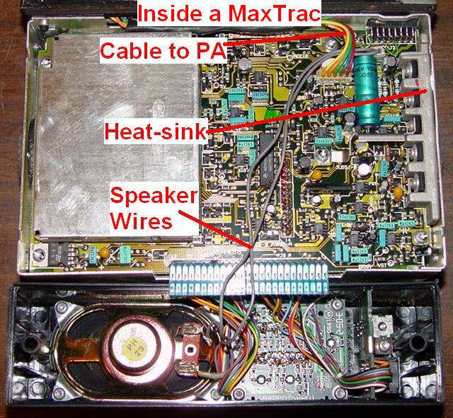
For comparison, here's the inside view of a MaxTrac. Notice the lack of shielding and no filter board between the logic board and control head.
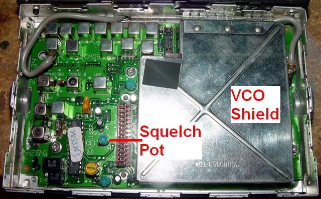
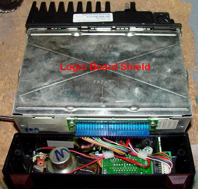
The GM300 logic board is significantly different from the MaxTrac logic board. It can control the RF board's local/DX circuit. The audio power amplifier is one single IC rather than discrete transistors. The heat-sink is considerably different and mounts only to the bottom of the chassis - no more T8 flat-head screws through the side of the chassis. There are far fewer components on the board too. All GM300 logic boards have a 16-pin accessory connector. A full metal shield covers the entire logic board, just like they have for the RF board; the MaxTrac only shields the microprocessor area. This further reduces spurious emissions.
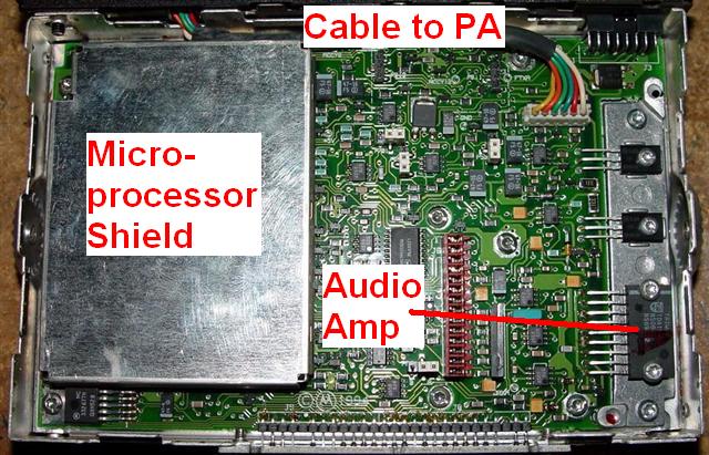
The GM300 audio amplifier drives both sides of the loudspeaker. Therefore you must NOT ground either pin 1 or pin 16 of the accessory connector. You must run two wires to an external speaker. The same circuit design and components are used on the Spectra radios and they suffer from the same restriction. Grounding either speaker lead may let out the chip's lifetime supply of smoke, even though the manufacturer claims the ICs are short-circuit-proof.
The internal loudspeaker for the GM300 (and MaxTrac/Radius) radios is p/n 5080085D03, however this part number has been replaced by p/n 5004639J01. This is a 22 ohm, 5 watt speaker that retails for around $7US in early 2009. An alternate speaker, with integral mounting flanges, is p/n 5080496Z01. All of these are No Longer Available through Motorola, but can be found on popular auction sites.
The GM300 RF power amplifier has a thermistor mounted near the final transistor, so it actually senses the heat-sink temperature. The logic board uses this to control the output power in a more reasonable way; the power will be reduced if/when the power amplifier gets hot enough, not when the microprocessor "thinks" it's getting hot from extended use. This makes GM300 radios more suitable for repeater transmitter or link channel usage (they still need adequate forced-air cooling). This extra signal requires a 6-wire cable and connector between the PA and the logic board (the MaxTracs only have a 5-wire cable and connector). I have heard that you can use a GM300 PA in a MaxTrac by snipping the temperature sensor wire off the connector, but I personally would not butcher either the radio or the cable that way. Mike WA6ILQ reports that several GM300s have been modified by swapping the power amplifier heat sink casting with one made for a high power R1225 repeater. The repeater heat sink directly swappable, is much larger, has a huge fin area, and the result is much higher duty cycle. More info is on the R1225 page at this web site.
Blanking the Radio:
There doesn't seem to be a lab version of RSS for the GM300. You can fool RSS into thinking the radio is blank by manually erasing the serial number (filling it with spaces) and entering a few more bytes using the bit-banging facility available in the MaxTrac lab RSS program. After that, you should be able to initialize the radio using the GM300 RSS or write a previously saved code plug to the radio. Initialization is exactly the same as the steps you'd do for a MaxTrac: set the radio model number, frequency range, signaling features, panel number, serial number, key in the crystal data and 9.6V reading, and align the power amplifier and deviation circuits.
Note: people have used the MaxTrac lab RSS to blank GM300 radios. They then install a MaxTrac EPROM, make some changes to the logic board, and turn the radio into a MaxTrac, including the model number. Then they initialize it with MaxTrac RSS.
To blank the radio, you need to deposit the following data at the locations shown. These values came directly from a factory-fresh blank board. This data will go directly into the radio's memory. You may want to write down the contents of these locations first, incase something goes terribly wrong. Use this at your own risk. All values are hexadecimal.
| Loc | Data | Usage |
|---|---|---|
| B600 | 20 | Serial # |
| B601 | 20 | Serial # |
| B602 | 20 | Serial # |
| B603 | 20 | Serial # |
| B604 | 20 | Serial # |
| B605 | 20 | Serial # |
| B606 | 20 | Serial # |
| B607 | 20 | Serial # |
| B608 | 20 | Serial # |
| B609 | 20 | Serial # |
| B60A | FF | Panel # |
| B60B | FF | Model Index # |
| B60C | 1B | Product # |
| B60D | FF | SW Ver. |
| B60E | FF | ??? |
| B60F | 4F | ??? |
| B610 | FF | ??? |
After setting the memory to these values, the radio will appear blanked to the GM300 RSS, and you'll have to go through the blank board replacement procedure and either align the radio, or fill in the various fields with data that was previously there. You can also write any previously saved code plug to the radio, but make sure you use one that matches the band and number of modes.
During the first screen of the initialization procedure, you'll need to select the frequency range. Go through the entire list using the up-arrow, then go through it a second time to find the exact range. Once the correct range is chosen, you'll have no problem choosing a model number. If you don't see the expected range, go through the entire list again.
By the way, the RSS knows about the two "panel numbers" for these
radios:
004 for the single channel M10 and the 2 channel M120, and M130 radios and
005 for the multi-digit (8 or 16 channel) GM300 radios.
The value at location B60C is an entry number of the Product Series in the MDF file.
There are only four possible values and you must select a value for this location. The
value at location B60F seems to depend on which logic board is in the radio. There's a
checksum at location B611 but don't bother with it. The table below shows the values
that can go into these two locations, based on the logic board, maximum number of
channels, and the 9th character of the model number. All values are hexadecimal.
Anyone want to provide the values for the "To Be Determined" (TBD) locations?
| Product Series | Logic Board | #Ch | 9th char | B60C | B60F |
|---|---|---|---|---|---|
| Radius GM300 | Expanded | 16 | C | 1B | 4F |
| Radius GM300 | Masked | 8 | D | 1B | 45 |
| Radius M120 | Masked | 2 | D | 20 | TBD |
| Radius M10 | Masked | 1 | D | 21 | TBD |
| Radius M130 | Expanded | 2 | C | 29 | TBD |
You should always record the original values or make a backup when hex-editing any radio or file.
Common Problems:
For some reason, GM300s seem to be prone to losing receive sensitivity. Whether this is due to nearby excessive transmitter power or operator error, the eventual cause seems to be either shorted protection diodes across the receiver's input, or a dead first RF amplifier transistor. All of these components require removal of the RF board to access them, but replacement is quite easy. They're surface-mount, of course.
While not a problem, I encountered a VHF radio with a receiver that was a couple kHz off frequency. In addition, it had very distorted audio when I fed a 3 KHz deviated signal into it. The 2nd oscillator crystal frequency was a couple of KHz high too. Replacing the crystal got the receiver back on frequency but the audio distortion was eventually traced to the fact that this was a 12.5 KHz narrow-band receiver and would only accept a 2.5 KHz deviated signal. I had never encountered one like this before and it was completely useless for 5 KHz reception, which is the standard on VHF.
Another common issue is a dead 2nd oscillator crystal. This operates at 44.645 MHz and is used to convert the 45.1 MHz intermediate frequency signal down to 455 kHz for the detector. When the crystal dies, the receiver will hear absolutely nothing or it may only hear a really strong signal, like a portable transmitting two inches from the antenna jack. If you have a receiver capable of hearing the crystal frequency, you can pick it up if you remove the shield from the RF board and place the antenna within a few inches of the left side of the radio. If you don't hear the 44.645 MHz signal, the crystal needs to be replaced. These can often be found on a popular auction web site. The Motorola p/n is 48-80008K02 and the crystals are marked "44.645/08K02" so you know they're the right ones. The most recent crystal I replaced is marked "44.645 08W05 NDK 9520" but I'm not sure how that differs from the "K02" crystal. In September 2019, Motorola claims the current part number for the 08K02 is 48-80606B02.
These radios often go way off frequency, to the point that the warp adjustment will not get it back where it belongs. The cause is most often dirty interconnection pins inside the radio. These are between the RF board and the logic board. On the MaxTrac, they are attached to the logic board; on the GM300 the strip of pins is mounted on the chassis and both boards plug into it. Remove both boards, clean these pins, and reinstall the boards. While the radio is apart, clean the front panel connectors too. These same connectors get dirty on MaxTracs as well, but for some reason they don't often cause serious problems like they do on the GM300. See this article for details and photographs.
I discovered that the RX Audio output on the accessory jack pin 11, with JU551 in the de-emphasized/muted position (B) has negative peak clipping (distortion) present on a 5 KHz deviated signal with a 300-400 Hz modulating tone. This may also be present on the MIC jack pin 8. It is caused by too much gain in the final audio stage ahead of the volume control. Two 16-channel radios had this problem; I don't know if all GM300s (and their related models) do. I fixed this by soldering a 22k resistor from pin 1 to pin 2 of U553B to reduce the gain by about 50%. The radio now exhibits no clipping with deviations as high as 7 KHz.
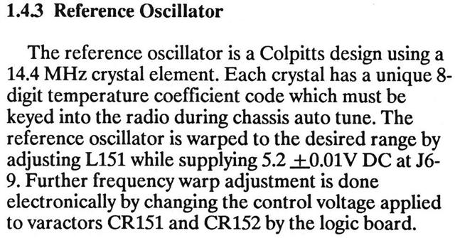
Reference Oscillator Coarse Adjustment Procedure:
Rather than type this paragraph, here it is directly from the service manual. This same procedure (with different part references) could also be used with MaxTrac radios.
Manuals and RSS:
Acknowledgements and Credits:
Dave N1OFJ supplied the GM300 and MaxTrac 50 radios. These photos were taken at his shack.
All photographs were taken, and are copyright, by the author.
Much of the information for this article, and the scanned pages, were obtained from the official Motorola GM300 Service Manual.
Mike Morris WA6ILQ provided a lot of information. A few tidbits of information were gathered from various Internet sources.
GM300, MaxTrac, Radius, RSS, PL, DPL, MDC, and a bunch of other terms and things are trademarks of Motorola, Inc.
Contact Information:
The original author, Robert Meister WA1MIK, is a silent key as of June 2021. The current page maintainer can be contacted by way of the "Currently Maintained by" link above.
Back to the top of the page
Maxtrac Index
Motorola Index
Back to Home
This article first posted 28-Sep-2006.
This web page, this web site, the information presented in and on its pages and in these modifications and conversions is © Copyrighted 1995, (date first posted), and (date of last update) by Kevin Custer W3KKC and multiple originating authors. All Rights Reserved, including that of paper and web publication elsewhere.