Back to Home
By Robert W. Meister WA1MIK

|
Motorola index Back to Home |
Motorola PM1200 Notes By Robert W. Meister WA1MIK |
|
General Information:
The Motorola PM1200 radio, parts, and support ended around 2017, which is about the same time Motorola bought Vertex. The Vertex VX-6000 high-power low-band mobile radios were also discontinued shortly thereafter. Icom never made a high-power low-band mobile radio. This leaves the Kenwood TK-690H as the only high-power low-band mobile radio you can still buy.
This article is a collection of hints, tips, and oddities of the PM1200 that should make your life easier. Click on any image or photo for a larger view.
Differences between the VX-6000 and PM1200:
The Vertex VX-6000 and Motorola PM1200 are quite similar internally and have nearly identical specifications. Both can be dash-mounted or trunk (remote) mounted. The most obvious difference is the control head. The VX-6000 has an extra PF button where the PM1200 has a modular MIC jack.
The VX-6000 has two proprietary 14-pin MIC jack connectors on the sides of the control head or side or rear of the remote-mount adapter. The PM1200 has a standard modular MIC jack on the front of the control head.
The VX-6000 has a DB-25F connector on the rear for accessories. The PM1200 has a Motorola 20 pin rectangular Accessory Connector on the rear.
The VX-6000 has a 3.5mm tip-sleeve jack on the rear for an external loudspeaker. Inserting a plug disconnects the internal speaker. The PM1200 has two pins on the Accessory Connector for attaching an external speaker. These are used in dash-mount installations. In remote-mount situations, there is a 3.5mm tip-sleeve jack on the rear of the remote control head adapter chassis.
The VX-6000 has a UHF-female RF connector on the rear. The PM1200 has a mini-UHF-female RF connector on the rear.
The DC Input connector on both radios is also the same one as used on the Kenwood TK-690H. It has two red wires and two black wires, due to the heavy current demand when the radio is running at full power.
The table below summarizes the different features.
| Feature | Vertex VX-6000 | Motorola PM1200 |
|---|---|---|
| MIC Connector | 14-pin proprietary | 8-pin RJ45 modular |
| Number of MIC Connectors | Two | One |
| MIC Connector Location | Sides of control head | Front of control head |
| Accessory Connector | DB-25F | 20 pin flat connector |
| External Speaker Connector | 3.5mm tip-sleeve | 20 pin flat connector |
| Front/Rear Speaker Selection | 3.5mm speaker jack | Programmed PF button |
| Antenna Connector | UHF-female | Mini-UHF-female |
Looking for a schematic diagram? The closest thing you'll find is the Vertex VX-6000L dash-mount Service Manual. Motorola published a "Basic Service Manual" that has a lot of good info inside that applies to both radios, but nothing really technical, and no actual schematic.
Band Identification:
The multi-character Motorola Model Number, on the sticker somewhere on the radio chassis, actually has a position for the band. The model number may start with "AA" indicating it was made in or for the American market. The next three characters are "M32" indicating a mobile PM1200 radio. The next character is the band indicator: "B" for 29.7-37 MHz, "C" for 37-50 MHz. This will be followed by "M" to indicate up to 125 watts of RF power. The rest of the characters aren't that important. To summarize:
Just to confuse things, the Basic Service Manual specification pages state "Low Band A" covers 29.7-37 MHz, and "Low Band B" covers 37-50 MHz. It doesn't help that one page shows "Low Band A" covering 37-50 MHz and right next to it "Low Band B" covering 37-50 MHz. Best thing to do is go by the letter - B or C - you find in the model number after the AAM32.
Ignition Control:
In the MaraTrac and older high-power trunk-mount radios, a pair of fused wires (orange and green) from the control head allowed flexible Ignition Control. In some dash-mount radios - such as the MaxTrac - a fuse on the logic board inside the radio enables Ignition Control when removed. In more modern radios, such as the CDM-series, Ignition Control is accomplished by a setting in the programming software. In the PM1200, it's something different.
First, you need to supply +12V to the radio's main power connector AND the ignition control input (pin 10) on the Accessory Connector. Then, to activate or de-activate Ignition Control, press and hold the POWER and PF2 buttons simultaneously for a few seconds until "IGN ON" or "IGN OFF" is displayed for a short period indicating whether Ignition Control is ON (enabled) or OFF (disabled). The Programmable Function (PF) buttons are directly below the display. PF1 is the one nearest the center of the control head, or the left-most button. PF2 is to its right. Pressing any of the other buttons during power-up may put the radio into a different mode, so it's best to avoid trying them.
Entering Programming Mode:
Make sure the radio has main power and ignition control power and the radio is turned off.
Connect the modular programming cable to the front panel MIC jack. This is a standard RJ45-type two-wire serial cable that is used by many Motorola radios. It requires a RIB and a serial port on the computer. There are also so-called RIB-less cables including USB to RJ45 cables. If you don't have a serial port, you should obtain a USB cable that uses the FTDI FT232R chip. These seem to be the ones that are most compatible with Motorola radios. The one I tried worked flawlessly. It is available on ebay by seller BlueMax49ers.
To enter programming mode, press and hold the PF3 button then press and hold the POWER button simultaneously for a few seconds, until the control head displays "PC CLONE". At this point you can begin programming the radio with CPS. After you're done programming, turn the radio off to exit programming mode. Apparently you can leave it in programming mode for the entire programming session (reading, writing, and multiples thereof).
In case you ever have to do it, if you press and hold the PF1 button while turning on the radio, the radio enters the "SB CLONE" mode. On the VX6000 this allows you to clone radio to radio, without a computer, using a special cable. I don't know if the PM1200 actually supports this. The User manual mentions cloning but gives no details how to do it. The PM1200 programming software has a "clone" function that lets you write the user programmable information from one code plug to another radio, which must be the same model and operating band. Cloning preserves the model, serial, and tuning data. You need to use PF1 rather than PF3 when programming the optional ANI board that can be installed inside the radio.
Programmable Function Button Power-On Sequence Summary:
The various PF button functions, when pressed and held while turning the radio on, are summarized below. Remember, PF1 is the left-most button underneath the display window.
| Button | Function with Power Button | Display Shows |
|---|---|---|
| PF1 | Put radio into ANI Programming mode | SB CLONE |
| PF2 | Enable or Disable Ignition Control | IGN ON or IGN OFF |
| PF3 | Put radio into PC Programming mode | PC CLONE |
| PF4 | Locks radio into power off mode | Nothing at all |
If you should power up while pressing PF4, you can recover by powering up while pressing PF3 to enter PC Programming mode, then cycling power.
External Loudspeaker:
Both radios have an oval loudspeaker inside the control head. The Vertex VX-6000 has an ungrounded 3.5mm jack for an external speaker; insertion of a plug disconnects the internal speaker. Both sides of the speaker are driven and sit at about +6VDC, so do not ground either lead coming out of the speaker jack, or you will destroy the audio amplifier IC inside the radio. Even though it claims to be short-circuit proof, it's not.
The PM1200 has provisions for an external speaker via pins 1 and 16 of the Accessory jack. Many other Motorola radios use a jumper (pin 15 to pin 16) on the Accessory plug that connects the internal speaker. The Motorola Basic Service Manual shows a pin diagram with "RSSI" on pin 15, yet a wiring diagram has "INT SP" on pin 15 and shows a jumper from pin 15 to pin 16 to enable the internal speaker, however nothing in the radio connects to pin 15. This same diagram shows a 3.5mm speaker jack inside the radio, and that jack isn't present at all. An external speaker connected to pins 1 and 16 worked just fine. Pressing any button caused a beep to be heard out of that speaker.
There's also a control head button function that can be used to mute or un-mute the speakers or select the internal/front and/or external/rear speaker. On the radio I played with, the internal speaker did not work even with the speaker jumper on the Accessory plug, however the mute/un-mute function did seem to work because it shut off the speaker audio completely. Oddly, the "Speaker Change" function on the PF4 button performed differently whether it was on the short press or the long press. On the short press it selected the speaker(s); on the long press it muted the speaker(s). Front, both, or rear speaker selection worked as indicated except the front speaker never worked. Without an accurate schematic diagram, I was unable to troubleshoot the internal speaker audio further.
The 16-pin Accessory Plug is an AMPMODU MOD IV series Locking connector p/n 104422-1, Digikey p/n 104422-1-ND. The 20-pin Accessory Plug is p/n 104422-2, Digikey p/n 104422-2-ND. Both use pins p/n 1-87309-3, Digikey p/n A3007-ND.
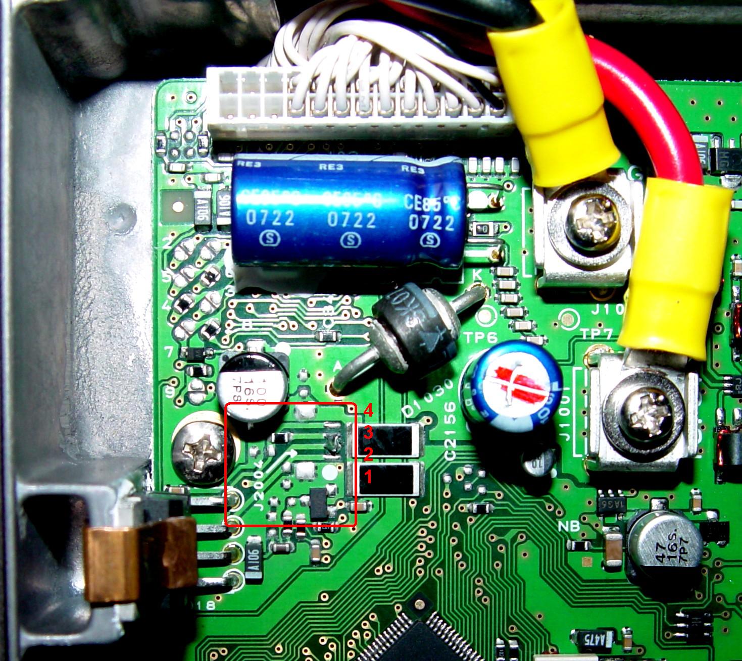
John W1GPO took another PM1200 apart and determined that there was NO signal path to the front panel connector for the speaker audio. It stopped at J2004 on the main board, a spot that had a 4-pin connector going to the 3.5mm external speaker jack on the back of the VX6000. With that jack and connector missing, there was no way audio could come out of the audio amplifier IC and get to the front panel. John determined that adding a solder blob / jumper from J2004 pin 1 to pin 2, or from pin 2 to pin 3, fed audio to the front panel connector and that allowed the internal speaker to operate. I verified that "fix" and the internal speaker now works when "Front + Rear" or "Rear" speaker is selected via the "SPEAKER CHANGE" function that we programmed into PF4. See the photo below of the left rear corner of the main (front) circuit board for the location of J2004 (next to the audio amplifier IC that uses the side of the chassis as a heat sink) and the pin numbering. Luckily pins 2 and 3 are the middle two pins so they're easy to get to and recognize.
Remote Control Head Adapter:
Apparently the control head can be mounted directly to the front of the VX-6000 or PM1200, or remote-mounted via an adapter chassis. This chassis has the 3.5mm tip-sleeve jack for the external speaker, and plugging one in disconnects the internal speaker on the VX-6000 but not on the PM1200. If the control head is mounted directly to the front of the radio, the external speaker would connect to the Accessory Connector pins 1 and 16. To disable the internal speaker, either unplug it inside the control head or program a front panel button for "Speaker Change" where you can select the Front, Front+Rear, or Rear loudspeaker.
Why Vertex CE-49 Programming Software May Not Work:
The Vertex CE-49 programming software, used with the VX-6000, is similar to the CPS used for the Motorola PM1200. The radio firmware and programming cable are completely different however. It seems that the Vertex radios use TWO data lines (transmit and receive) and it may matter which MIC connector you use (left or right), whereas the Motorola radios use one shared data line that plugs into the modular MIC jack on the control head. A RIB or equivalent level-shifting circuit (provided by a USB programming cable) is required to convert the bipolar RS-232 data levels to the 5V level utilized by the radio. I was unable to get CE-49 V5.17 to read or write the PM1200 with either a RIB or a USB cable, however both cables worked fine with the PM1200 CPS R01.00.
Which Remote Cable Connector To Use:
A remote mount radio has four connectors behind the front cover plate and two on the back of the remote control head adapter chassis. The main or only control head always uses the RED connector on both ends. You can have a combination of one or two control heads attached to one radio chassis, or one control head attached to two radios, for multi-band operation.
Extending the Frequency Range:
The PM1200 CPS saves a 32,768-byte code plug file with a .cps extension. The layout and format of the operating band values was the same as in the personality file saved by the Vertex CE-49 program, however the entire second half of the file - used by the second radio in a two-radio configuration - was blank.
I read the code plug from the radio and saved it to disk. I hex-edited the band limit and changed it from 37-50 MHz to 37-54 MHz. I loaded the modified code plug into CPS and it let me enter frequencies in the 6-meter range. When I tried to write the code plug to the radio, CPS apparently first read a portion of the code plug from the radio, probably to verify the model and serial numbers, and noticed that the band limits were different; it then displayed an error message to that effect and refused to go any further.
I was told that I could use the CE-49 program to at least write the code plug to the PM1200. I had to change the file extension from .cps to .c49 in order for the CE-49 program to at least read it in. CE-49 V5.17 would neither read nor write to the PM1200 with either a RIB or a USB programming cable, whereas PM1200 CPS R01.00 worked fine with either cable.
So, we're left with two issues:
I found a work-around procedure to handle this situation:
The same procedure can be used to allow a low-split (29.7-37 MHz model) radio to cover the 10-meter band. You will still have to adjust the VCO; use the same procedure as detailed for the Vertex VX-5500 or VX-6000 radios. This programming/software problem appears to be solved.
Little Programming Tidbits:
When you enable transmit TPL in any personality (channel), a field appears on the General Settings screen in CPS that lets you choose TPL Reverse-Burst as None (default), Standard, or Non-Standard. Of course they don't tell you the specifics or difference, but since this is a Motorola radio, you probably want to set it to Standard for use in a Motorola system. Hopefully Standard means 120-degree phase shift while Non-Standard means 180-degree phase shift.
Alignment Software and Cable:
There was a SVC-49 program available for the VX-5500 and VX-6000 radios. It required a special programming cable that connected to the DB-25 Accessory Connector on the back of those radios. The PM1200 has a similar, if not identical, program and requires a special cable that plugs into the 20-pin Accessory Connector on the back of the radio. The correct cable seems to be a mystery and is tied in with a Flash Upgrade capability. I do know that the normal programming input for the PM1200 is via one pin on the MIC jack. I'm guessing that the 20-pin Accessory Connector signals on pins 17-20 are used by the programming setup.
Credits and Acknowledgements:
A lot of information came from the Motorola PM1200 Basic Service Manual. Additional information came from the Vertex VX6000 Service Manuals.
John W1GPO loaned me a dash-mount PM1200, USB serial cable, power cable, microphone, and Accessory Plug with wires for testing and programming the radio. He also discovered the issue with the internal speaker and missing J2004.
Contact Information:
The author can be contacted at: his-callsign [ at ] comcast [ dot ] net.
Back to the top of the page
Up one level (Motorola index)
Back to Home
This page originally posted on Monday 30-Mar-2020
Article text, artistic layout, all photographs, and hand-coded HTML © Copyright 2020 by Robert W. Meister WA1MIK.
This web page, this web site, the information presented in and on its pages and in these modifications and conversions is © Copyrighted 1995 and (date of last update) by Kevin Custer W3KKC and multiple originating authors. All Rights Reserved, including that of paper and web publication elsewhere.