Main index page
Coaxial Collinear Antenna
By Paul Kelley N1BUG
Photos by the author

|
Antenna Systems page Main index page |
Construction Notes on a WA6SVT Coaxial Collinear Antenna By Paul Kelley N1BUG Photos by the author |
|
I needed a good UHF repeater antenna and didn't have much money to spend on it. I decided to build one following WA6SVT's original article on repeater-builder.com, incorporating a few of my own ideas into it. Here are my notes on construction. Please refer to the original article for the background theory.
I decided to build a 10 element version of the antenna using Belden 8267 coax guts. I found this to be a very snug fit inside the K&S 5/16 inch brass tubing. Often it is impossible to push it through at room temperature. I discovered a trick which solves this problem nicely. Cut the pieces of coax guts to length (or a bit longer than needed) and put them in a freezer for about 30 minutes. Keep the brass tubing at room temperature. The well chilled pieces of coax guts will easily slip into the tubing! Note that if they were very snug to begin with you may not be able to pull them out once they warm up, so center them as needed when you put them in.
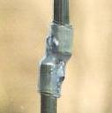
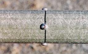
I used RG-214/U (double silver plated braid) for the "feedline" pigtail at the base of the antenna. Here is a photo of the joint where the brass tubing meets the coax braid after soldering (refer to step 8 in the WA6SVT article). The teflon tape helps keep the coax from becoming distorted during soldering. It takes a lot of heat to get a nice solder joint here.
For the decoupling sleeve I used a piece of 3/4 inch type M copper tubing with an appropriate end cap and a short length of 11/32 inch K&S brass tubing. This photo shows the completed decoupling sleeve assembly and some elements prior to preparing the ends.
Here is a picture of the elements after preparing the ends. I find it helpful to tin the center conductors prior to solding elements together. Note that I have made the top element out of a single piece of 5/16 inch tubing as described by Kevin Custer W3KKC in his construction ideas. The arrow points out the solder where the center conductor comes through the tubing and is soldered to it. This does take a bit of extra effort trying to get the (pre-tinned) center conductor to exit through a hole that is just slightly larger than the conductor itself. I like the end result so I consider it worth the trouble.
I find it best to use a lot of heat for a short period of time when soldering the elements together. This minimizes melting the coax dielectric. I also like to keep a damp rag handy for cooling the piece immediately after soldering. Here is an element joint after soldering.
On my "revision 2" antenna, after some discusstion with Mike, WA6SVT, I decided to stiffen the joints with short sections of adhesive lined heat shrink tubing. There was some concern about the tubing detuning the elements, so I built the antenna and measured its resonant frequency before applying any shrink tubing. I then put on all the shrink tubing and measured the resonant frquency again. It dropped 2.2 MHz or approximately 0.5% due to the addition of the shrink tubing. I believe this is insignificant in terms of pattern tilt for antennas up to at least 12 elements, and is not enough to cause SWR problems unless you need very wide bandwidth. However, on subsequent antennas I have cut the elements 0.5% shorter to begin with, thus the antenna ends up right on the design frequency after the tubing is put on. The tubing I used was 1/2 inch diameter double wall polyolefin tubing with polyamide adhesive. Results may vary with other types of shrink tubing! Here is a joint after a 1.3 inch lenth of shrink tubing has been added.
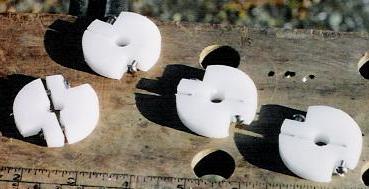
Instead of styrofoam, I used spacers made from delrin to keep the antenna centered in the radome. I feel they are much more durable. Here again I tested a prototype antenna with two types of styrofoam spacers and with my delrin spacers. There was no measurable difference in resonant frequency. My radomes are made from multiple sections of fiberglass tubing and the inside diameter is smaller at the joints. This presented a problem since the antenna could not be slid into the radome with the spacers in place. I solved this problem by making all the spacers (except the bottom one) in two halves and using 6-32 machine screws to clamp them together on the elements. See photo. I used stainless steel machine screws and again can measure no affect on the antenna. However, nylon screws should do nicely if you are concerned about metal screws in close proximity to the elements. If metal screws are used, just make sure they do not touch the radiating element. Using this method I am able to slide my antenna up through the bottom section of radome, with no spacers in place (except the bottom one), then add a couple spacers, slide the next section of radome down over the antenna from the top, add more insulators, more radome, etc. until it is finished. My radome for the 10 element UHF version is 3 sections.
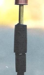
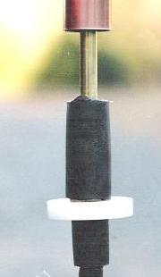
The weight of my antenna is supported inside the radome by the bottom spacer, which is of special design (again made from delrin). I put a 3 inch length of 1 inch diameter thick wall shrink tubing lined with hot melt adhesive over the soldered joint where the feedline pigtail comes out of the brass tubing. After shrinking this tubing in place, I then put a 1.5 inch length of the same tubing over the first, aligning its top edge with the top of the first piece. After shrinking, this provides a "shoulder" which is more than capable of supporting the weight of the antenna. My bottom delrin spacer is a one piece design consisiting of a delrin disk whose outer diameter is a nice fit inside the radome and inner diameter is a snug fit over the bottom of the shrink tubing. See photos. Visible in the rightmost photo below are ventillation holes in the delrin spacer to allow air flow and prevent condensation inside the radome.

After the antenna is in the radome I drill four 1/8 inch holes through the radome into the edge of the delrin spacer and secure it with #8x1/2 inch self tapping stainless steel screws. Don't drill too far into the spacer or use screws long enough to damage the feedline!
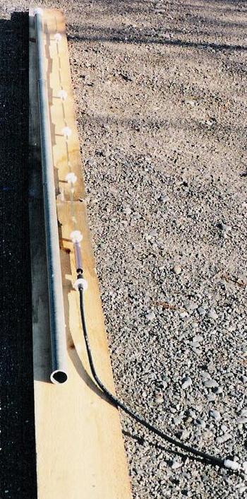
Here is a photo of a completed antenna and radome before final assembly. Note the delrin spacers have to be reomoved for assembly into this radome (except the bottom one). I put them on for this photo to illustrate what the assembly looks like with them in place.
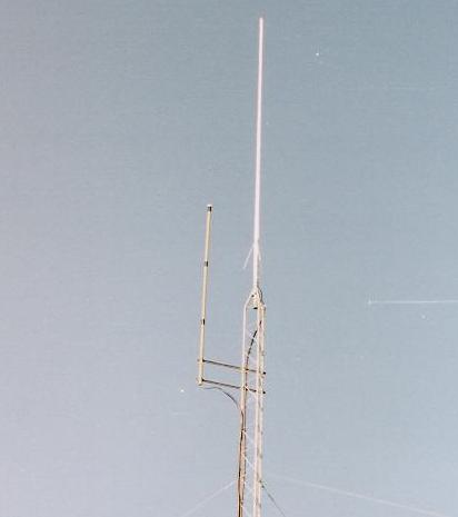
Finally, here is one of these antennas in place on a repeater tower. My current method of waterproofing the radome joints leaves something to be desired, although it works (for now). It is simply a couple of layers of 3M vynl tape over the joint, with a black UV-resistant cable tie to prevent the end from trying to unravel. The top cap on the radome is made of PVC.
![]()
Back to the top of this page
Repeater-Builder Antenna Systems page
Repeater-Builder Main index page
All photos and text on this web page are © Copyright Paul Kelly N1BUG 2005
Paul's HTML edited to fit the requirements of www.repeater-builder.com by Mike Morris WA6ILQ
This page last updated 25-Oct-2009
The information presented in and on this web site is © Copyrighted 1995 - present by Kevin Custer W3KKC and multiple originating authors.